HAL Id: hal-02457543
https://hal.telecom-paris.fr/hal-02457543
Submitted on 28 Jan 2020
HAL is a multi-disciplinary open access
archive for the deposit and dissemination of
sci-entific research documents, whether they are
pub-lished or not. The documents may come from
teaching and research institutions in France or
abroad, or from public or private research centers.
L’archive ouverte pluridisciplinaire HAL, est
destinée au dépôt et à la diffusion de documents
scientifiques de niveau recherche, publiés ou non,
émanant des établissements d’enseignement et de
recherche français ou étrangers, des laboratoires
publics ou privés.
Design Space Exploration with Deterministic Latency
Guarantees for Crossbar MPSoC Architectures
Bogdan Uscumlic, Andrea Enrici, Renaud Pacalet, Amna Gharbi, Ludovic
Apvrille, Lionel Natarianni, Laurent Roullet
To cite this version:
Bogdan Uscumlic, Andrea Enrici, Renaud Pacalet, Amna Gharbi, Ludovic Apvrille, et al.. Design
Space Exploration with Deterministic Latency Guarantees for Crossbar MPSoC Architectures. 2020
IEEE International Conference on Communications (ICC): Communication Software, Services and
Multimedia Applications Symposium, Jun 2020, Dublin, Ireland. �hal-02457543�
Design Space Exploration with Deterministic
Latency Guarantees for Crossbar MPSoC
Architectures
Bogdan Uscumlic
∗, Andrea Enrici
∗, Renaud Pacalet
†, Amna Gharbi
†, Ludovic Apvrille
†, Lionel Natarianni
∗and Laurent Roullet
∗∗Nokia Bell Labs, Paris-Saclay, France
e-mail: [email protected]
†LTCI, T´el´ecom Paris, Institut Polytechnique de Paris, Paris, France
e-mail: [email protected]
Abstract—MPSoC and NoC systems are often used in complex telecommunication systems, which in the 5G era need to enable telecommunication services with unprecedented latency char-acteristics. Indeed, new services emerge, needing deterministic latency guarantees with virtually no system jitter, during the lifetime of the established telecommunication service. In this work, for the first time, we propose an optimal solution for a design space exploration (DSE) optimization problem, that performs all the traditional DSE tasks, but with end-to-end deterministic latency guarantees. We focus on MPSoC or NoC architectures with crossbars, although this work can be easily extended to more complex architectures. More precisely, our contributions in this work are the following: 1) we propose a novel method for deterministic scheduling in MPSoC and NoC architectures with a crossbar; 2) we propose an optimal solution in the form of an integer linear program (ILP) for DSE problem with end-to-end deterministic latency guarantees; 3) we identify the trade-off between the latency due to the use of crossbar time slots and the application execution time at different processing elements. The numerical results suggest that the proposed deterministic scheduling method can efficiently use all 100% of the crossbar capacity, depending on available application load and system parameters.
Index Terms—design space exploration, data communication, linear programming, crossbar embedded system architectures.
I. INTRODUCTION
T
HE design space exploration (DSE) problem consists in optimizing the allocation of application tasks to the processing units which are part of an embedded system and in ensuring the allocation of sufficient resources for data com-munications. This task is very complex, but it becomes even more difficult with the complexity of multi-processor system-on-chip (MPSoC) and network-system-on-chip (NoC) systems.Furthermore, recently a new requirement has arisen from the need of Industry 4.0 and 5G systems: the need for deterministic latency. Deterministic or fixed latencies, with strict jitter limitations introduce additional requirements to computer networks, both in optical and electronic domain, but also to NoC and MPSoC systems. The issue of deterministic latency was not really tackled so far in embedded system design space exploration, as it can be seen, e.g. from [1].
Also, new technologies are currently being introduced for facilitating automatic service deployment and orchestration in the 5G context. The cloud-native approach is a novel paradigm for supporting the telecommunication services in 5G architec-tures. The key idea of this concept is to enable a joint network and cloud infrastructure evolution, with “softwarization” of the telecommunication infrastructure [2]. Cloud-native 5G systems provide many advantages, such as the use of cloud infrastruc-ture for deploying new telecommunication services, reduction of investments, the automation, easy network update, etc. One of the enabling technologies for cloud-native 5G systems is network and computation acceleration, in which FPGAs (Field-Programmable Gate Array) based transport infrastruc-ture play an important role. In such a context, we are interested in looking for the solutions of DSE problems that can benefit from FPGA acceleration and that can model the deterministic latency constraints, as required by 5G applications.
The register allocation and the instruction scheduling are the classical DSE optimization problems in traditional compilers, that can be assessed by using integer linear programming [3]. These problems are NP-hard for realistic processors or NP-complete, when reduced to graph coloring problem [4]. The mapping of applications’ tasks to processing elements in MPSoC and NoC architectures is a DSE problem that can be addressed by using linear programming or constraint programming [5].
However, to the best of our knowledge, an optimal solution of DSE problem with deterministic latency guarantees has not been proposed so far for MPSoC or NoC systems with crossbars. The current work, for the first time, addresses this problem, by using a linear programming approach. We also propose a novel method for crossbar scheduling with deterministic traffic support, in this context.
The remainder of the document is organized as follows. Section II provides more details about the studied hardware platform and the assumptions about the considered DSE problem, with a focus on deterministic latency requirements. Section III is devoted to the related work. In Section IV we describe our mathematical model for the optimal solution of
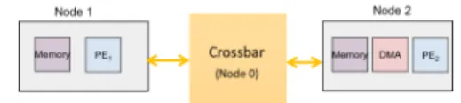
Fig. 1. Multi-processor system-on-chip (MPSoC) with a crossbar. Each “node” consists from a processing element in combination with other elements (e.g. a memory, a direct memory access (DMA) controller, etc.).
the above DSE problem based on integer linear programming (ILP) and we detail the propossed crossbar scheduling. In Section V we report the numerical results obtained by using the optimal ILP solution. Finally, the concluding remarks and the perspectives are provided in the final section.
II. CONSIDEREDEMBEDDEDSYSTEM ARCHITECTURES ANDDETERMINISTICLATENCYGUARANTEES
A. Considered MPSoC and NoC architectures
The typical hardware platform that we consider is heteroge-neous and can be composed of different hardware components. These components are different “processing elements” (PE), DMA controllers, memories and various interconnects (e.g. buses, crossbars). The processing elements can be CPUs, GPUs, FPGAs or other components. The use of crossbars is frequent in real-time data flow embedded systems.
This is why in the present work, we focus on modeling a MPSoC or a NoC architecture containing a crossbar. An example of such an architecture is shown in Fig. 1, which il-lustrates a MPSoC system composed of N “nodes” (processing elements).
The optimal solution of the DSE problem for the system in Fig. 1 comprises: 1) the allocation of PEs to applications’ tasks; 2) the scheduling of the tasks on the allocated PEs and 3) the crossbar scheduling of data communications between the tasks. Furthermore, in our solution of the DSE problem, the objective function of the optimization minimizes the end-to-end deterministic latency for communications between the tasks. To find such a solution, we model the behavior of the crossbar present in the system.
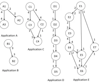
The applications and their tasks are represented in the form of Homogeneous Synchronous Data Flow (HSDF) graphs, e.g. as shown in Fig. 2. This figure shows the applications considered in the current work, inspired by those studied in [5].
B. Deterministic latency guarantees
Our work, for the first time, takes into account the as-sumption on the required end-to-end “deterministic” latency guarantees for data communications between the applications’ tasks. Deterministic latency is actually the fixed latency for communications between different points in a MPSoC or NoC
Fig. 2. Example of simple streaming applications presented with HSDF graphs.
system. The guarantees for deterministic latency are usually followed by the requirement for a “zero” jitter. “Zero” jitter usually means that no jitter is present in the system due to the system design or task scheduling. The only present jitter is the one due to the physical effects that cannot be assessed. After reviewing the related work in the following section, in Section IV we present a mathematical model describing the previously defined DSE problem, together with a method for deterministic scheduling in the crossbars. Please note that our solution with the end-to-end deterministic service guarantees supposes that the traffic benefiting from such a service has a deterministic time profile. In other words, we suppose that the traffic flows exchanged between the applications’ tasks can be represented with the periodic arrivals of equal portions of data. In that way, at the output of the crossbar system, the deterministic traffic profile will be preserved for each flow traversing the system.
III. RELATED WORK
The traditional approach to the mapping of HSDF applica-tion graphs to the processing elements consists in decoupling the problem in two steps: assigning actors (computations) to PEs (“spatial allocation” or “mapping”) and ordering the execution of these actors (“temporal allocation” or “schedul-ing”). However, the complete strategies also exist and they aim at simultaneously retrieving the optimal solution for the mapping and scheduling problems. These complete strategies have the advantage of obtaining more optimized solutions at cost of increased computational complexity. Furthermore, such strategies are attractive for execution scenarios where a solution is computed once and applied during a given time window, when all the relevant characteristics (e.g. depen-dencies, execution time of functions) are statically known and are guaranteed not to change. These scenarios can be relevant even for modern signal processing (e.g. 5G systems) and multimedia applications. These applications impose, to execution resources, workloads that dynamically evolve over the system’s lifetime.
In this context, historically, the most well-known complete strategy is based on linear programming. Early works are the task partitioning with timing constraints in the SOS system [6], [7] and the mapping in a function of the execution time, pro-cessor and communication costs [8]. Furthermore, [9] presents a solution for optimizing the cache memory hierarchy for distributed real-time systems. An alternative approach to linear programming is constraint programming (CP), considered in [5], [10], [11]. While linear programming is more often used to solve the spatial allocation, CP seems to be well suited to solve the temporal allocation [12].
Approximate solutions based on heuristics were also pro-posed. Very often, the heuristics approximate the optimal solu-tions described by linear programming models. A comparison of three heuristics based on genetic algorithms, simulated annealing and tabu search is presented in [13]. Other examples are the heuristics considering the scheduling policy [14] or aiming to solve the mapping problem, as in [15] and [16].
More recently, the emergence of complex communication architectures (e.g. crossbars, heterogeneous buses, NoCs) has urged the exploration of novel design spaces. The focus of recent work is more on NoC architectures [17], [18] with the objective of reducing energy consumption, data-access costs and the contention, respectively. The presented work differentiates from the existing work as we target deterministic crossbar based architectures, where our formulation retrieves solutions that guarantee the respect of tight latency constraints that are necessary for deterministic data communications.
IV. INTEGER LINEAR PROGRAMMING SOLUTION FOR THE
DSEPROBLEM WITH DETERMINISTIC LATENCY
GUARANTEES
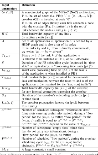
The optimal solution of the previously defined problem is formalized by an integer linear programming (ILP) model. The ILP model solves the DSE problem with the end-to-end deterministic latency guarantees (as defined in Section II), for a given MPSoC (or NoC) architecture and for a given set of applications. The list of input parameters to the ILP formulation is given in Tab. I.
The MPSoC architecture is defined by a graph G(V, E) in Tab. I, with graph vertices (nodes) that are enumerated with positive numbers in range [0, N ]. The links connect the MPSoC nodes with the crossbar (CB), which is supposed to be installed at node “0” of the graph G(V, E). The bandwidth of the links is limited to BWl. The internal bandwidth of the
crossbar is limited to BWcb.
The notion of “time slots” is introduced to model: 1) the scheduling cycle of all processing elements (equal to S time slots) and 2) the scheduling cycle of the crossbar (equal to Scb
time slots). The scheduling of the processing elements and of the crossbar repeats after S and Scb time slots, respectively.
The duration of each time slot is expressed in generic “pro-cessing time units” [p.t.]. In general case, S 6= Scb.
Each application a is represented by a HSDF graph, and it is defined as a set of tasks. Data communication between the tasks m and n of a given application a is described by
TABLE I INPUTPARAMETERS
Input Definition
parameters
G(V, E) A non-directed graph of the MPSoC (NoC) architecture; V is the set of nodes (i.e. PEs); V = {0, 1, 2, ..., N }; crossbar (CB) is installed at node “0”;
E is the set of edges (links); each link connects a node with the crossbar (Fig. 1); path(i, j) is the set of links between the nodes i and j (i, j ∈ V ). BWl Total bandwidth capacity of any link l
(in arbitrary units [a.u.])
A Set of all applications a; application a is defined by a HSDF graph and is also a set of its tasks;
if the tasks k1and k2from a directly communicate,
we write: “k1→ k2= direct”
Γk,a,i Binary := 1 if the task k of the application a
is allowed to be installed at PE i, or := 0 otherwise S Duration of the PE scheduling cycle (expressed in “time
slots” or equivalently, in “processing time units [p.t.]”) Lk,a,i Worst case processing time (in [p.t.]) of the task k
of the application a when installed at PE i Tm,n,a Link bandwidth (in [a.u.]) required for deterministic
data communication between the tasks m and n of the application a (i.e. required for the “(m, n, a) traffic”) BWcb Total bandwidth capacity (in [a.u.]) of the crossbar,
for any internal connection traversing the crossbar Scb Duration of the crossbar’s scheduling cycle (in [p.t.]
or time slots)
Lcb(i, j) The crossbar propagation latency (in [p.t.]) between
PEs i and j
αm,n,a Number of scheduled subsequent “information slots”
(time slots carrying useful information), during a “flow period” for the (m, n, a) traffic; “flow period” for the (m, n, a) traffic is equal to αm,n,a+ βm,n,a;
αm,n,aand βm,n,adepend on the value of T m,n,a.
βm,n,a Number of subsequent “empty slots” (time slots
that do not carry any information), during a “flow period” for the (m, n, a) traffic;
Fm,n,a Number of scheduled “flow periods”, during the crossbar
scheduling cycle Scb, for the (m, n, a) traffic;
obviously, Fm,n,a= S
cb/(αm,n,a+ βm,n,a)
M ; ε A large constant; a small constant
four different parameters in Tab. I: Tm,n,a (for the required
link bandwidth); Fm,n,a, αm,n,a and βm,n,a (the crossbar
parameters depending on Tm,n,a). Finally, the worst case
processing time of a task k of the application a, when running on the PE i, is equal to Lk,a,i.
In Tab. II, we provide a list of the output variables used in the model (all the other variables not listed in Tab. II, but used in the formulation, are binary, auxiliary variables). The key variables are xk,ai and sk,ai , which determine which PE is allocated to which application and the processing starting times at different PEs, respectively.
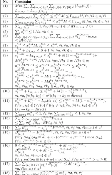
Next, Tab. III provides the formulation constraints. In this table and in the remainder of this paper, the following index notation is used: i, j ∈ V /{0}, a ∈ A, σ ∈ [0, Scb− 1] and
l ∈ E (the sets and the values V , A, Scb and E are defined
in Tab. I). Please note that the solution provided by a ILP formulation is optimal, for a specified objective function. In our case, the objective function (eq. (1) in Tab. III) minimizes the total end-to-end deterministic latency for each pair of tasks that communicate directly (as defined by the HSDF graph of the application containing these tasks). In the following, we discuss in detail all the constraints from Tab. III.
TABLE II OUTPUTVARIABLES
Output Definition Variables
xk,ai Binary := 1 if the task k of the application a is installed at PE i or := 0, otherwise
zi,jm,n,a Binary := 1 if the tasks m and n of the application a are installed at PEs i and j (respectively)
or := 0, otherwise
sk,ai Natural, indicating the starting time slot (in the range [1, S]) for the execution of the task k of the application a, when k is installed at PE i; equal to 0 if k is not installed at PE i mσ
i,j Binary := 1 if the matching between input/output
ports i and j of the crossbar happens at time slot σ, or := 0, otherwise
B(i,j)m,n,a,σ/ Binaries, := 1 if the (m, n, a) traffic in the crossbar, pm,n,a,σ(i,j) exchanged between PEs i and j, is transported
starting from/by using (respectively) the time slot σ or := 0, otherwise
TABLE III
INTEGERLINEARPROGRAMMINGFORMULATION
No. Constraint (1) M in[P
a
P
(m,n)∈a2P(i,j)∈(V /{0})2(Lcb(i, j)+
Lm,a,i+ Ln,a,j)zm,n,ai,j ]
(2) P n∈a,n6=k P jz k,n,a i,j ≤ x k,a
i M ≤ Γk,a,iM, ∀a, ∀k ∈ a, ∀i
(3) P m∈a,m6=k P iz m,k,a i,j ≤ x k,a j M ≤ Γk,a,jM, ∀a, ∀k ∈ a, ∀j (4) P i,jz m,n,a
i,j = 1, ∀a, (∀(m, n) ∈ a2)(Tm,n,a6= 0)
(5) P
ix k,a
i ≤ 1, ∀a, ∀k ∈ a
(6) P
(i,j)∈V2:l∈path(i,j)PaP(m,n)∈a2zi,jm,n,aTm,n,a
≤ BWl, ∀l
(7) sk,ai ≤ xk,ai M, xk,ai ≤ sk,ai , ∀i, ∀a, ∀k ∈ a (8) sk,ai + Lk,a,i≤ S + 1, ∀i, ∀a, ∀k ∈ a
(9) sk1,a1
i + Lk1,a1,i≤ ski2,a2+ M (1 − n
k1,k2,a1,a2
i,i )+
M δk1,k2,a1,a2
i,i , ∀i, ∀a1, ∀a2, ∀k1∈ a1, ∀k2∈ a2
nk1,k2,a1,a2 i1,i2 ≤ x k1,a1 i1 , n k1,k2,a1,a2 i1,i2 ≤ x k2,a2 i2 , nk1,k2,a1,a2 i1,i2 ≥ x k1,a1 i1 + x k2,a2 i2 − 1, sk2,a2 i2 < s k1,a1 i1 + M (1 − δ k1,k2,a1,a2 i1,i2 ) − ε, sk2,a2 i2 ≥ s k1,a1 i1 − M δ k1,k2,a1,a2 i1,i2 ,
∀i1, ∀i2, ∀a1, ∀a2, ∀k1∈ a1, ∀k2∈ a2
(10) sk1,a i + Lk1,a,i≤ s k2,a i + M (1 − n k1,k2,a,a i,i ),
∀i, ∀a, (∀(k1, k2) ∈ a2)(k1→ k2= direct)
(11) sk1,a i1 + L k1,a i1 + Lcb(i1, i2) ≤ s k2,a i2 + M (1 − n k1,k2,a,a i1,i2 ),
(∀(i1, i2) ∈ (V /{0})2)(i16= i2), ∀a, (∀(k1, k2) ∈ a2)
(k1→ k2= direct)
(12) P
i:i6=jmσi,j≤ 1, ∀j, ∀σ;
P
j:j6=imσi,j≤ 1, ∀i, ∀σ
(13) P
a
P
(m,n)∈a2zm,n,ai,j Tm,n,a
≤P σmσi,j/Scb· BWcb, ∀i, ∀j (14) P σB m,n,a,σ i,j = z m,n,a
i,j Fm,n,a, ∀i, ∀j, ∀a, ∀(m, n) ∈ a2
(15) Bm,n,a,σ1
(i,j) = B m,n,a,σ2
(i,j) , ∀i, ∀j, ∀a, ∀(m, n) ∈ a 2
(∀σ1, ∀σ2)(σ2≡ σ1+ w · (αm,n,a+ βm,n,a) mod Scb),
(∀w, Fm,n,a> w ≥ 0) (16) 0 ≤ pm,n,a,σ2 (i,j) − B m,n,a,σ1 (i,j) + M · γ m,n,a,σ1 (i,j) , Bm,n,a,σ1 (i,j) ≤ 0 + M · (1 − γ m,n,a,σ1 (i,j) ), ∀i, ∀j, ∀a, ∀(m, n) ∈ a2 (∀σ1, σ2)(σ2≡ (σ1+ w) mod Scb), (∀w, αm,n,a> w ≥ 0) (17) P σ P
(i,j)∈(V /{0})2B(i,j)m,n,a,σ≤ M · zm,n,ai,j ,
∀a, ∀(m, n) ∈ a2
(18) P
a
P
(m,n)∈a2pm,n,a,σ(i,j) ≤ mσi,j, ∀σ, ∀i, ∀j
A. Constraints ensuring the allocation of PEs
The constraint (2) ensures that tasks and applications can be installed only at the allowed subsets of PEs (these subsets are defined by the input parameters “Γk,a,i”). The constraint
holds for each task that is an origin (i.e. a “source”) of data communication towards some other task in a HSDF graph. The constraint (3) has the same role as the previous constraint, but it holds for the tasks receiving some traffic from some other tasks in HSDF graphs.
Next, for a given pair of tasks (m, n) that are directly con-nected in the HSDF graph of a given application a (resulting in Tm,n,a6= 0), there must exist only a single pair of processing
elements i, j (on the MPSoC chip), to which the tasks m and n are allocated, respectively. This property is ensured by the constraint (4).
The constraint (5) ensures that at most one PE can be allocated to a given task and a given application. Finally, to limit the capacity of data communications over each link in MPSoC, we use the constraint (6).
So far, the constraints were dealing with properly allocating PEs to applications’ tasks. These constraints provide the basic limitations on the PE allocation variables: xk,ai and zm,n,ai,j . Next, we address the scheduling of tasks on PEs.
B. Constraints for the scheduling of tasks on PEs
The key variable defining the scheduling of tasks on PEs in MPSoC is sk,ai . This variable defines the starting time of execution of the task k (of the application a) at PE i. To simplify the constraints, the possible values of sk,ai are situated in the range [1, S].
The function of the following constraint, (7), is to connect the variables xk,ai and sk,ai . Indeed, xk,ai and sk,ai can both be different than 0, but only simultaneously. The constraint (8), provided next, make sure that the total execution time of each task at a given PE is not greater than the end of the scheduling period S.
The constraints also need to address the case when tasks of different applications share the same PE. This is achieved by the constraint (9). For proper functioning of the constraint, the following two conditions need to be satisfied: 1) the inequality connecting the variables sk,ai needs to take into account the order of their scheduling on the PE (this is achieved by introducing the auxiliary decision variable δk1,k2,a1,a2
i,i ); 2) the
condition can be enforced only if the allocation of PEs to applications’ tasks also holds (this is achieved by introducing the auxiliary decision variable nk1,k2,a1,a2
i,i ).
Next, when scheduling two tasks of the same application on the same PE, if the tasks “directly communicate”1, the task that is the origin of direct communication shall be executed first, which is enabled by the constraint (10). Similarly, the inequality (11) is needed to set the scheduling relation between different tasks of a given application.
Fig. 3. Crossbar architecture with the periodic scheduling model (with scheduling period Scb). α(i) and β(i) correspond to “(mi, ni, ai) traffic”,
i.e. they define αmi,ni,ai and βmi,ni,ai.
C. Model and constraints for the crossbar scheduling The architecture of the crossbar is shown in Fig. 3. We suppose that the crossbar operates in discrete time slots. The scheduling in the crossbar repeats after the scheduling cycle of Scbtime slots. Each time slot is allocated to one pair of
input-output links. The bandwidth available during the input-input-output interconnection traversing the crossbar is equal to BWcb. Time
slot allocation is always performed in a way that satisfies the matching condition of the crossbar. “Matching” is a crossbar configuration property according to which no more than a single output can be connected to any single input (and vice versa), at any given time.
Data communications are supposed to be periodic (deter-ministic), as in Fig. 3. The scheduling in the crossbar allows to multiplex different applications’ tasks at each PE connected to the crossbar. When multiplexing data, the size of “flow periods” of different data flows must correspond to the value of Scb. Indeed, the “flow period” (defined in Tab. I) for (m, n, a)
traffic flow is equal to αm,n,a+ βm,n,a. This is why, in order to ensure a feasible solution for the crossbar scheduling, we suppose that Scbis equal to the least common multiple of all
flow periods αm1,n1,a1+ βm1,n1,a1, αm2,n2,a2+ βm2,n2,a2, ...,
etc.
In the formulation, the constraint (12) is introduced to en-force the matching condition in the crossbar. The capacity con-straint (13) limits the total available capacity for transport of deterministic data communications. The constraints (14)-(16) are the scheduling constraints, calculating the key scheduling variables Bm,n,a,σ(i,j) and pm,n,a,σ(i,j) . Finally, to connect different variables describing the crossbar and the PE allocation process, we introduce the constraints (17) and (18).
Please note that the previously defined DSE problem be-comes equivalent to traditional processor allocation problem for N = 3. The latter problem is generally considered to be NP-hard for the objective functions that optimize applications’ performances [1], so it can be considered that our DSE problem has the same computational complexity.
1“Direct communication” relates to the presence of a connecting arrow in
HSDF graph.
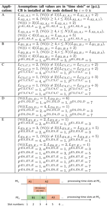
Fig. 4. A motivating example: the crossbar architecture for N = 2
V. NUMERICAL RESULTS
We have implemented the previous ILP formulation in the IBM CPLEX software. In this section we report the optimal results of simulations, for various application assumptions. A. The application assumptions
We consider a motivating example and three application scenarios. In the following, we describe the application as-sumptions for the scenarios 1, 2 and 3, while the motivating example has slightly different assumptions. All the values chosen here are for illustration purpose, and can be changed for different set of applications and PEs. We suppose that Γk,a,i = 1 (∀k, ∀a, ∀i) and Lcb(i, j) = 2 p.t. (∀i, ∀j), which
corresponds to the latency of CB. Next, N = 4, Scb= 8 p.t.,
BWl= 1.2 Gbit/s and BWcb= 133 Mbit/s.
The capacity vm,n,aof each (m, n, a) traffic flow is written
next to the corresponding link in Fig. 2. In this figure, value of vm,n,a is given in (crossbar) time slots. The link
bandwidth required for the (m, n, a) traffic flow is then equal to Tm,n,a = vm,n,a/Scb· BWcb. Other assumptions on the
considered applications (from Fig. 2) are summarized in Tab. IV. We consider the following three application scenarios:
1) Scenario 1. Linear combination of applications A and B. We consider that S = 10. The application load increases and the results are calculated for the points {B, A+B, A+2B, 2A+2B, ...} This scenario illustrates the achievable crossbar time slot occupancy (i.e. the average percentage of occupied crossbar time slots over the active input-output connections).
2) Scenario 2. Fixed application load of 2A+2B. For such fixed application load, we increase the value of S, starting from S = 10 (we increase the computational power of PEs), to study the dependency of the optimal solution and the crossbar time slot occupancy from the available processing power in the system.
3) Scenario 3. Randomly chosen application load from the set {A, B, C, D, E}. For S = 17, the application load is randomly generated out of the applications from Fig. 2. This scenario illustrates the behavior of the scheduling and the PE allocation process in case of random application load.
B. Motivating example: 3-node crossbar architecture
First, for illustration purposes, we consider a simple cross-bar system composed of three nodes (N = 2), as in Fig. 4. The applications to be allocated in this system are the applications A and B from Fig. 2, with the same assumptions as in Tab. IV. The size of scheduling cycle on any PE is supposed to be S = 5 p.t., while Scb and all the other parameters have the
TABLE IV
ASSUMPTIONS ONAPPLICATIONS INFIG. 2 Appli- Assumptions (all values are in “time slots” or [p.t.]; cation: CB is installed at the node defined by i = 0 ): A LA1,A,1= 1, (∀i)(i 6= 1)(LA1,A,i= LA1,A,1+ 2)
LA2,A,1= 4, (∀i)(i ≥ 1, i ≤ 3)(LA2,A,i= LA2,A,1),
(∀i)(i > 3)(LA2,A,i= LA2,A,1+ 2)
FA1,A2,A= 2, αA1,A2,A= 1, βA1,A2,A= 3
LA3,A,4= 2, (∀i)(i ≥ 4, i ≤ N )(LA3,A,i= LA3,A,4),
(∀i)(i < 4)(LA3,A,i= LA3,A,4+ 5)
FA1,A3,A= 4, αA1,A3,A= 1, βA1,A3,A= 1
B LB1,B,4= 2, (∀i)(i ≥ 4, i ≤ N )(LB1,B,i= LB1,B,4), (∀i)(i < 4)(LB1,B,i= LB1,B,4+ 2) LB2,B,4= 1, (∀i)(i ≥ 4, i ≤ N )(LB2,B,i= LB2,B,4), (∀i)(i < 4)(LB2,B,i= LB2,B,4+ 2) FB1,B2,B= 1, αB1,B2,B= 3, βB1,B2,B= 5 C LC1,C,1= 2, (∀i)(i 6= 1)(LC1,C,i= LC1,C,1+ 2) LC2,C,2= 1, (∀i)(i 6= 2)(LC2,C,i= LC2,C,2+ 2) FC1,C2,C= 4, αC1,C2,C= 1, βC1,C2,C= 1 LC3,C,2= 1, (∀i)(i 6= 2)(LC3,C,i= LC3,C,2+ 3) FC1,C3,C= 4, αC1,C3,C= 1, βC1,C3,C= 1 LC4,C,2= 1, (∀i)(i 6= 2)(LC4,C,i= LC4,C,2+ 3) FC2,C4,C= 1, αC2,C4,C= 1, βC2,C4,C= 7 FC3,C4,C= 1, αC3,C4,C= 1, βC3,C4,C= 7
D (∀i)(LD1,D,i= 1, LD2,D,i= 6)
FD1,D2,D= 1, αD1,D2,D= 1, βD1,D2,D= 7 (∀i)(LD3,D,i= 4, LD4,D,i= 1)
FD2,D3,D= 2, αD2,D3,D= 1, βD2,D3,D= 3
FD3,D4,D= 1, αD3,D4,D= 1, βD3,D4,D= 7
E (∀i)(LE1,E,i= 2, LE2,E,i= 1)
FE1,E2,E= 2, αE1,E2,E= 1, βE1,E2,E= 3
LE3,E,3= 3, (∀i)(i 6= 3)(LE3,E,i= LE3,E,3+ 5)
FE2,E3,E= 2, αE2,E3,E= 1, βE2,E3,E= 3
LE4,E,1= 1, (∀i)(i 6= 1)(LE4,E,i= LE4,E,1+ 5)
FE3,E4,E= 4, αE3,E4,E= 1, βE3,E4,E= 1
(∀i)(LE5,E,i= 2, LE6,E,i= 2, LE7,E,i= 1)
FE4,E5,E= 2, αE4,E5,E= 1, βE4,E5,E= 3
FE5,E6,E= 1, αE5,E6,E= 3, βE5,E6,E= 5
FE6,E7,E= 1, αE6,E7,E= 1, βE6,E7,E= 7
FE1,E7,E= 1, αE1,E7,E= 1, βE1,E7,E= 7
FE1,E5,E= 1, αE1,E5,E= 1, βE1,E5,E= 7
FE4,E6,E= 1, αE4,E6,E= 1, βE4,E6,E= 7
Fig. 5. The resulting scheduling on PEs in the motivating example
The resulting scheduling on PEs in this example is shown in Fig. 5. The value of the objective function (the end-to-end deterministic latency) is equal to 13 p.t. (indeed, the overall latencies for traffic flows (A1, A2, A), (A1, A3, A) and (B1, B2, B) are 5, 5 and 3 p.t., respectively). The traffic flow (A1, A3, A) is routed over the crossbar. The results show that the crossbar latency between the tasks A1 and A3 has been properly taken into account.
C. Results for a crossbar architecture withN = 4
Next, Scenarios 1, 2 and 3 are considered in a larger MPSoC, composed of five nodes (i.e. for N = 4 in Fig. 1).
1) Scenario 1: The simulation results are provided in Fig. 6, for linearly increasing application load. The figure shows
Fig. 6. Scenario 1: total end-to-end deterministic latency and CB slot occupancy for a linearly increasing traffic load
Fig. 7. Scenario 2: total end-to-end deterministic latency and CB slot occupancy for a fixed traffic load
Fig. 8. Scenario 3: total end-to-end deterministic latency and CB slot occupancy for a random traffic load
the increase of the objective function value (the end-to-end deterministic latency) with the increase of the scheduled load. One of the key results is that the crossbar slots can be highly
occupied (up to 100%), for sufficiently high data commu-nication loads. This confirms the efficiency of the proposed deterministic scheduling method for the slot allocation in the crossbar. These results also identify a trade-off between the use of crossbar’s time slots (which introduces the crossbar transit latency) and the use of processing elements’ time slots.
2) Scenario 2: In order to further explore the trade-off be-tween the use of thecrossbar and PEs in MPSoC architecture, we test Scenario 2 in the same five-node MPSoC topology.
The simulation results are provided in Fig. 7. We observe what happens with the increase of the computational power of PEs. We mimick the computational power increase with the increase of the scheduling cycle S for a fixed application load (indeed, without changing the values of tasks’ processing times Lk,a,i, the increase of S is equivalent to the increase of
PE’s computational capacity).
Fig. 7 clearly shows that the increase of computational power of processing elements results in:
• the decrease of the objective function value; indeed, the increase of the computational power of PEs allows to tasks to use “cheaper” processing elements, i.e. those that are more efficient in terms of latency.
• the decrease of the crossbar time slot occupancy; indeed, this is another expected outcome, since the use of crossbar is penalized by the crossbar latency (supposed to be 2 p.t. in this example), so the crossbar will be used only when needed.
3) Scenario 3: Finally, in Scenario 3, we increase the total application load in the system. Furthermore, the applications are randomly generated, to test the behavior of the scheduling and the PE allocation process for a randomly generated application matrix.
The results are summarized in Fig. 8. The found values of the end-to-end deterministic latency are higher in this case, because the maximum application load is greater than in the previous scenarios. The time slots in the crossbar are used up to 37.5 %, with tendency of increased time slot use at higher loads. Indeed, for lower application loads, there are still available time slots at latency-efficient PEs, so the use of crossbar is not required. This trend does not differ in linear and random load scenario. Furthermore, such behavior once again confirms the trade-off between the use of time slots in the crossbar and at processing elements.
VI. CONCLUSIONS ANDPERSPECTIVES
We have proposed an optimal solution for the DSE problem in a crossbar MPSoC system. Our solution and scheduling model for the first time provide end-to-end deterministic latency guarantees in such a context. The optimal solution of DSE problem is based on an integer linear program. The new optimization problem has a high computational complexity.
We have identified a trade-off between the use of crossbar’s time slots for supporting data communications and the use of processing elements’ time slots. Since the crossbar introduces latency, the optimal solution will use the crossbar time slots as needed, and in a proportion corresponding to the relative
“cost” of crossbar communication latency and processing latency at different processing elements.
By using the proposed optimal solution as a benchmark, an approximate heuristic algorithm can be developed, that would be able to solve large instances of the problem, in a minimum computation time. The development of such a solution is left for future work. Such approximate algorithm could be then used in the context of accelerated processing with determinis-tic latency guarantees in cloud-native 5G systems.
REFERENCES
[1] A. D. Pimentel, “Exploring Exploration: A Tutorial Introduction to Embedded Systems Design Space Exploration,” in IEEE Design & Test, vol. 34, no. 1, pp. 77-90, Feb. 2017.
[2] 5G-PPP Software Network Working Group, “From Webscale to Telco, the Cloud Native Journey”, Overall Editor: Bessem Sayadi, July 2018, https://5g-ppp.eu/wp-content/uploads/2018/07/5GPPP-Software-Network-WG-White-Paper-23052018-V5.pdf, accesed on September 02, 2019
[3] Chia-Ming Chang, Chien-Ming Chen, Chung-Ta King, “Using integer linear programming for instruction scheduling and register allocation in multi-issue processors”, Computers & Mathematics with Applications, Volume 34, Issue 9, 1997, Pages 1-14, ISSN 0898-1221
[4] Shlomit S. Pinter, “Register allocation with instruction schedul-ing.” In Proceedings of the ACM SIGPLAN 1993 conference on Programming language design and implementation (PLDI ’93), Robert Cartwright (Ed.). ACM, New York, NY, USA, 248-257. DOI=http://dx.doi.org/10.1145/155090.155114
[5] K. Rosvall and I. Sander,: A constraint-based design space exploration framework for real-time applications on MPSoCs. In: DATE, 6 pages, 2014.
[6] S.Prakashand, A. Parker,: SOS: Synthesis of Application Specific Hetero-geneous Multiprocessor Systems. In: Journal of Parallel and Distributed Computing, pp. 338 - 351, 1992.
[7] C. Lee, M. Potkonjak and W. Wolf,: System-Level Synthesis of Application-Specific Systems Using A Search and Generalized Force-Directed Heuristics. In: ISSS, pp. 2 - 7, 1996.
[8] A. Bender,: MILP based Task Mapping for Heterogeneous Multiprocessor Systems. In: EURO-DAC, pp.190 - 197, 1996.
[9] Y. Liand, W. H. Wolf,: Hardware/Software Co-Synthesis with Memory Hierarchies. In: IEEE Trans. On Computer-Aided Design of Integrated Circuits and Systems, pp. 1405 - 1417, 1999.
[10] A. Bonfietti, M. Lombardi, M. Milano, and L. Benini,: Maximum-throughput mapping of SDFGs on multi-core SoC platforms. J. Parallel Distrib. Comput. Vol. 73, n. 10, pp. 1337-1350, 2013.
[11] K. Kuchcinski,: Embedded System Synthesis by Timing Constraint Solving. In: IEEE Transactions on CAD, pp. 537 - 551, 1994. [12] M. Ruggiero, A. Guerri, D. Bertozzi, F. Poletti and M. Milano,
”Communication-aware allocation and scheduling framework for stream-oriented multi-processor systems-on-chip,”. In: DATE, pp. 6, 2006. [13] J. Axelsson: Architecture Synthesis and Partitioning of Real-Time
Synthesis: a Comparison of 3 Heuristic Search Strategies. In: CODES/CASHE, pp. 161 - 166, 1997
[14] P. Eles, Z. Peng, K. Kuchcinski, A. Doboliand, P .Pop,: Scheduling of Conditional Process Graphs for the Synthesis of Embedded Systems. In: DATE, pp. 132 - 139, 1998
[15] F. Guderian, R. Schaffer and G. Fettweis: ”Administration- and communication-aware IP core mapping in scalable multiprocessor system-on-chips via evolutionary computing,” 2012 IEEE Congress on Evolution-ary Computation, Brisbane, QLD, 2012, pp. 1-8.
[16] J. Lin, A. Gerstlauer, and B. L. Evans: Communication-aware Hetero-geneous Multiprocessor Mapping for Real-time Streaming Systems. J. Signal Process. Syst. Vol. 69, n. 3, 2012
[17] C.-L. Chou and R. Marculescu, ”Contention-aware application mapping for Network-on-Chip communication architectures,”. In: ICCD, pp. 164 - 16, 2008.
[18] I. Akturk and O. Ozturk, ”ILP-Based Communication Reduction for Het-erogeneous 3D Network-on-Chips,” 2013 21st Euromicro International Conference on Parallel, Distributed, and Network-Based Processing, Belfast, pp. 514-518, 2013.