HAL Id: hal-01685185
https://hal-mines-albi.archives-ouvertes.fr/hal-01685185
Submitted on 17 Nov 2020
HAL is a multi-disciplinary open access
archive for the deposit and dissemination of
sci-entific research documents, whether they are
pub-lished or not. The documents may come from
teaching and research institutions in France or
abroad, or from public or private research centers.
L’archive ouverte pluridisciplinaire HAL, est
destinée au dépôt et à la diffusion de documents
scientifiques de niveau recherche, publiés ou non,
émanant des établissements d’enseignement et de
recherche français ou étrangers, des laboratoires
publics ou privés.
Analytical and experimental investigation of the
delamination during drilling of composite structures
with core drill made of diamond grits: X-ray
tomography analysis
Jamel Saoudi, Redouane Zitoune, Suhasini Gururaja, Mehdi Salem, Salah
Mezleni
To cite this version:
Jamel Saoudi, Redouane Zitoune, Suhasini Gururaja, Mehdi Salem, Salah Mezleni. Analytical and
experimental investigation of the delamination during drilling of composite structures with core drill
made of diamond grits: X-ray tomography analysis. Journal of Composite Materials, SAGE
Publica-tions, 2018, 52 (10), p.1281-1294. �10.1177/0021998317724591�. �hal-01685185�
Analytical and experimental investigation
of the delamination during drilling of
composite structures with core drill
made of diamond grits: X-ray
tomography analysis
Jamel Saoudi
1,2, Redouane Zitoune
1, Suhasini Gururaja
3,
Mehdi Salem
1and Salah Mezleni
2Abstract
Among the various forms of material damage, exit-ply delamination has been identified as one of the most deleterious damage processes associated with drilling fibre-reinforced plastics. The thrust force has been cited as the primary cause for drilling-induced exit-ply delamination. Only one analytical model for the prediction of the critical thrust force responsible for delamination using core drills can be found in the literature. In this study, a realistic model to predict critical thrust force responsible for drilling-induced exit-ply delamination in a multi-directional carbon fibre-reinforced plastic laminate with core drill has been proposed. A comparison between the proposed model, literature model as well as the experimental tests conducted during punching tests is presented. The proposed model is found to correlate well with experimental punching tests. In fact, the maximum relative errors recorded between the experimental values of the critical thrust force and the measured values are around 15%. Micro-tomography experiments have also been conducted that capture the drilling-induced damage in multi-directional carbon fibre-reinforced plastics in great detail. The X-ray images highlight the difficulty in controlling the thickness of the uncut plies located under the core drill during punching tests that can be attributed to some deviations in predictions of critical thrust force. Postmortem examination of the blind holes after punching tests also confirms the presence of a net delamination near the vicinity of the nominal diameter of the core drill, which correlates well to the hypothesis of the analytical model.
Keywords
Modeling, exit-ply delamination, fracture mechanic, drilling, composite, core drill, X-ray tomography
Introduction
Nowadays, composite materials are being used widely compared to metallic materials ranging from aerospace to sport goods industries.1–3 The heterogeneous and anisotropic behavior of carbon fibre-reinforced plastic (CFRP) materials poses real problems in their machin-ing. In the aerospace industry, conventional drilling process is the most commonly applied method for gen-erating holes and then for riveting and fastening struc-tural assembly.4,5 However, this process of machining for composite materials has always been a challenge due to a host of difficulties. The mechanism of machin-ing for composite materials has been recognized as a process different from that of homogeneous and
isotropic materials.6,7 Moreover, several undesirable forms of damage (such as matrix cracking, mechanical and thermal degradation of the matrix, delamination and fibre breakage) induced by drilling drastically reduce the maximum failure stress and the endurance
1Institut Cle´ment Ader (ICA), UMR-CNRS 5312, ‘‘INSA, UPS, Mines Albi,
ISAE’’, France
2Ecole Nationale d’Inge´nieurs de Monastir, Tunisia 3Aerospace Engineering, Indian Institute of Science, India
Corresponding author:
Redouane Zitoune, ICA - UMR CNRS 5312. Universite´ de Toulouse, 133 c Avenue de Rangueil, 31077 Toulouse, France.
limit during static and fatigue tests of the machined specimens, respectively.6,7 It is important to note that the tool geometry plays a major role in drilling of com-posites followed by feed rate; many different geometry drill bits made of different tool materials have been tested in the literature.8–11Tool geometries can be sum-marized into six categories of drill bits: twist drill bit,11–15 step drill bit,16 brad point drill bit,16–19 slot drill bit,19–22 straight flute drill bit21,23 and trepanning tool (also known as core drill bit).10,24,25If we refer to the literature,18,19the analysis of variance conducted by several authors after the operation of drilling reveals that the main parameter affect the thrust force is the feed speed (by 90%). However, the spindle speed is responsible only for 5 to 8% of variation of the thrust force when the machining parameters change.
Most experimental work indicates that damages located at the wall of the hole and at the hole exit (delamination) are considered critical damages lower-ing the mechanical resistance of the structural parts during fatigue loading.26,27 Several authors have
con-firmed that the damage located at the wall of the hole is strongly influenced by the physics of cutting.28–31 In fact, when a conventional drill (e.g. twist drill) is used for drilling with its optimal machining parameters, the critical damage is located in the areas where the relative angle between the cutting lip and the fibre is equal to !45"or 90". However, in the case of drilling with a core
drill made of diamond grits and using optimal machin-ing parameters, the state of the wall of the hole is smooth and no critical damage area is observed.10
At the exit of the hole, the observed damage takes the form of delamination between the plies.31 This defect
appears when the thrust forces are too high, which gen-erates a crack propagating at the interface between the two plies.31–35 Different authors have shown that this damage is strongly affected by the feed rate and the geom-etry of the drill, the wear rate of the tool as well as the interface quality between the plies of the composite material.9–15The damage located at the hole exit is the main damage appearing in drilling composite materials. The size of the delamination zone has been shown to be related to the thrust force developed during the drilling process and it is believed that there is a ‘critical thrust force’ (CTF) below which no damage occurs.33–37In fact, delamination can be greatly reduced or eliminated by reducing feed rates near the exit and using backup plates to support and prevent deformations leading to exit side delamination.38–40
In order to predict the CTF responsible for the delamination during drilling with conventional drill (e.g. twist drill), many analytical and numerical models have been developed.33–40 Hocheng and
Dharan33 proposed the first analytical model for pre-diction of CTF based on linear elastic fracture mech-anics (LEFM) approach for an assumed isotropic material with a circular self-similar crack under a con-centric loading. Using the classical bending theory of thin circular plates for a point load and Griffith’s energy balance criterion, Hocheng and Dharan were able to derive a compact form of critical thrust force (CFT) for a particular material system. Jain and Yang34 modified Hocheng and Dharan’s simplistic model by assuming a more realistic elliptical damage zone representative of the inherent orthotropy of a uni-directional laminate (UD) laminate. Jain and Yang34 also proposed a unique variable feed rate strategy that enabled delamination-free drilling by reducing the feed rates as the drill bit approached the exit side of the hole. The main results show that it is possible to reduce the thrust force significantly by reducing the chisel edge width. Recently, Saoudi et al.35,36proposed a new model taking into account: (1) the orthotropic behavior of the composite; (2) the coupling between stretching and bending and (3) delineating the contri-bution of chisel edge and principal cutting edge in a twist drill. The predicted values of the CTF are in good agreement compared to those obtained experi-mentally. The small difference observed has been attrib-uted mainly to the variability in the thickness of the composite ply due to the process of manufacturing. The presence of this variability has been confirmed using X-ray tomography (in situ observation) con-ducted before and after punching tests on CFRP specimens. In addition, a three-dimensional (3D) finite element model based on the fracture mechanics allowing CTFs (for a conventional twist drill) respon-sible for delamination at the hole exit to be predicted is developed using multi-layers elements available in the library of the commercial software SAMCEF.41 In the numerical model, the distribution of the loading used corresponds to a contribution of 40% by the drill chisel edge and of 60% by the drill lips. The CTF predicted by this model was compared with Hocheng and Dharan predictions.33 The results showed that the analytical model underestimates the CTFs. These results are in good agreement with those observed in the literature.36–42
In the case of drilling with core drill, few works are available in the literature.10,24,25Cadorin and Zitoune10
have noticed that the machining quality of 3D woven composite obtained with core drill made of diamond grits is better compared to the one obtained with con-ventional drill with three cutting lips. In addition, the same authors have shown that when drilling is con-ducted with core drill using machining parameters
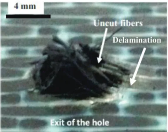
that are not optimal, severe damage was observed at the hole exit, such as delamination and uncut fibres (cf. Figure 1). The authors report that real time moni-toring of cutting forces during drilling reveals that delamination appears as axial thrust force reaches a crit-ical value. Thus, to overcome these kinds of damage during machining with core drill, it is important to pre-dict this critical value.
The unique analytical models available in the litera-ture to predict CTF during drilling with core drill are proposed by Hocheng and Tsao.24,25In these analytical models, authors assume isotropic properties for the CFRP plate in order to simplify the analysis to predict the CTF during drilling. The comparison between the predicted force and the measured values of the CFT showed that the relative deviation is around 30%; the deviation can be attributed to the over-simplistic iso-tropic material assumption and the variability in thick-ness of the composite laminate that results in errors in measurement of CTF experimentally.
The main objective of this study is to propose a new analytical model for predicting CTF for a core drill by assuming a more realistic orthotropic material defin-ition for the composite laminate. Experimental valid-ation of the CTF at different ply thickness under the tool has also been carried out using quasi-static punch-ing tests. Finally, the damage development durpunch-ing drilling has been extensively studied using X-ray tom-ography observations.
Physical model for the prediction of the
critical force when the core drill is used
For the exit-ply delamination, the transverse displace-ment w generated by the drill movedisplace-ment is associated
with the work done by the thrust force FZ, which is
used to deflect the plate as well as to propagate the inter-laminar crack33
The energy balance equation gives
dW! dU ¼ GIcdA ð1Þ
where
dW: is the work done by the external forces. dU: is the infinitesimal strain energy.
GIc: is the critical strain energy release rate in mode I.
dA: is the infinitesimal increase in area of crack.
Delamination model using core drill
24Figure 2 depicts the schematics of a core drill and the induced delamination. In this figure, the tool is charac-terized by the inner radius c*, outer radius c and thick-ness t. FZ is the thrust force related to the lateral
uniform distribution load q, H is the workpiece thick-ness, h is the uncut depth under tool and a is the radius of delamination at which the plate is embedded at the edge. To obtain the CTF, Hocheng and Tsao24 have considered that the material behavior is isotropic. In addition, pure bending of the laminate is assumed in the model. However, the relation between (F1) and (F2)
can be written as F2¼ (1-b)2 F1.
Proposed model for the core drill
Figure 3(a) depicts the schematics of the load applied by a core drill.
For the development of the model, the following main assumptions are considered:
– LEFM has been considered.
– Orthotropic behavior and pure bending of the laminate are assumed.
– Drilling-induced delamination has been idealized as a mode I crack propagation phenomenon; the applied thrust force that causes onset of mode I delamination is defined as the CTF.
– The delaminated zone is considered to be a circu-lar plate with orthotropic properties.
– Contact between core drill and composite is assumed to result in uniformly distributed loading.
– A circular pre-crack of nominal diameter is assumed to be present at the start of the analysis.
Figure 1. Damage generated by worn out core drill after machining with too high feed rate. Feed rate f¼ 0.08 mm/rev, spindle speed of 5000 r/min at the exit of the hole.10
In order to get the CTF applied by the core drill, the method of superposition is applied. Since the tool-work contact is located in a circular area at the bottom of the drill core, the thrust force due to the action of the core drill is obtained by subtracting the downward force (F1) from downward force (F2) as shown in
Figure 3(b) and (c).
In this case, the uniformly distributed lateral load q1 acting on the downward area and the uniformly
distributed lateral load q2 must be equal. However,
the relation between (F1) and (F2) can be written as
follows
F2¼ ð1 ! !Þ2F1 ð2Þ
The thrust force can be written then as follows FZ¼ F1! F2¼ !ð2 ! !ÞF1 ð3Þ
Delamination analysis: model (b). For this model, the energy balance equation (1) can be expressed as follows
dW1! dU1¼ G1IdA ð4Þ
For an orthotropic circular plate of radius a, clamped at the edges and subjected to uniformly dis-tributed load over a central circular area of radius c, the following closed form solutions for transverse
Figure 2. Circular plate model for delamination analysis using a core drill.25(a) Cross view of delamination area. (b) Thrust force model. 2a = -c q FZ c (a) (b) (c) c* c F1 q1 2a c c* F2 2a q2
deflections of the plate have been detailed by assuming an axisymmetric analysis43
(i) 0& r & c inner portion
w¼64"DF1 4a2! 3c2þ 4c2logc a ! " h ! 2r2 c 2 a2! 4 log c a # $ þr 4 c2 % ð5Þ
(ii) c& r & a outer portion
w¼64"DF1 4a2þ 2c2! 2r2 2þc 2 a2 # $ & þ4c2logr aþ 8r 2logr a i ð6Þ where D¼1 8ð3D11þ 2D12þ 4D66þ 3D22Þ ð7Þ D: is the bending rigidity of the plate.
Dij(i, j¼ 1, 2 and 6): are the coefficients of the matrix
of bending stiffness.
. Strain energy derivation dU1:
The expression for strain energy can be written as follows 2U1 ¼ ZZ D11 @2w @x2 # $2 þD22 @2w @y2 # $2 " þ 4D66 @2w @x@y # $2 þ2D12 @2w @x2 # $ @2w @y2 # $# dxdy ð8Þ
Equation (8) can be written as
2U1¼ U11þ U22þ U66þ U12 ð9Þ where U11 ¼ ZZ D11 @2w @x2 # $2 dxdy U22 ¼ ZZ D22 @2w @y2 # $2 dxdy U66 ¼ ZZ 4D66 @2w @x@y # $2 dxdy U12 ¼ ZZ 2D12 @2w @x2 # $ @2w @y2 # $ dxdy 9 > > > > > > > > > > > > > > = > > > > > > > > > > > > > > ; ð10Þ
In polar coordinates, equation (10) can be written as
U11¼ Z2" 0 Za 0 D11 @2w @r2cos 2 # þ@w@rsin 2# r # $2 rdrd# U22¼ Z2" 0 Za 0 D22 @2w @r2sin 2 # þ@w@rcos 2# r # $2 rdrd# U12¼ Z2" 0 Za 0 2D12 @2w @r2 cos 2 # þ@w@rsin 2# r # $ ( @ 2w @r2sin 2 # þ@w@rcos 2# r # $ rdrd# U66¼ Z2" 0 Za 0 4D66 @2w @r2sin # cos # !@w@rsin # cos #r 0 B B @ 1 C C A 2 rdrd# 9 > > > > > > > > > > > > > > > > > > > > > > > = > > > > > > > > > > > > > > > > > > > > > > > ; ð11Þ where
(r,y): are the polar coordinates.
By introducing equations (5) and (6) into (11), we obtain U11¼ 32DF1 ' (2D11 " 48c2log ca ' ( !6c4 a2 ! 16c2þ 24a2 h i U22¼ 32DF1 ' (2D22 " 48c2log ca ' ( !6c4 a2 ! 16c2þ 24a2 h i U12¼'32DF1(2D"12 32c2log' (ca !4c 4 a2 !323c2þ 16a2 h i U66¼ 32DF1 ' (2D66 " 64c 2log c a ' ( !8c4 a2 !643c2þ 32a2 h i 9 > > > > > > > > = > > > > > > > > ; ð12Þ Strain energy derivation
2dU1¼dU1 da da¼ dU11 da þ dU22 da þ dU12 da þ dU66 da # $ da ð13Þ Finally, by replacing equation (12) into equation (13), we obtain dU1¼ F2 1a 32"D D0 8D 3s 4! 12s2þ 12 ' ( da ð14Þ where
s¼ac: drill diameter to delamination diameter ratio ð15Þ
D0¼D11þ D2 22þD12þ 2D3 66: stiffness coefficient ð16Þ
. Work of external forces derivation dW1:
The expression of the work of the external forces is given by W1¼ Z 2" 0 Z c 0 q1wrdrd# ð17Þ
By substituting equations (5) and (6) into equation (14), we obtain W1 ¼ F 2 1 32"D 4c 2log c a ! " ! c 4 2a2! 4 3c 2 þ 2a2 & % ð18Þ dW1¼ dW1 da da ð19Þ Introducing equations (5), (15) and (18) into equa-tion (19), we obtain dW1¼ F2 1a 32"D s 4 ! 4s2þ 4 ' ( da ð20Þ
Delamination analysis: model (c). This model is similar to the latter model (b). Thus, the following equations can be given as follows
dW2! dU2¼ G2IdA ð21Þ
. Strain energy derivation dU2
dU2¼dU2 da da¼ F2 2a 32"D D0 8D 3s )4 ! 12s)2þ 12 ! " da ð22Þ
. Work of external forces derivation dW2
dW2¼ F 2 2a 32"D s )4 ! 4s)2þ 4 ! " ð23Þ where s) ¼ca) ð24Þ
Delamination analysis for core drill: model (a). For this model, the energy balance equation (1) can be expressed as follows
d Wð 1! W2Þ ! d ðU1! U2Þ ¼ GIdA ð25Þ
where
dA¼ 2"ada ð26Þ
By introducing equations (2), (14), (20), (22), (23) and (26) into equation (25), we obtain
F1¼ " ffiffiffiffiffiffiffiffiffiffiffiffiffiffiffiffiffiffiffiffiffiffiffiffiffiffiffiffiffiffiffiffiffi 64GID k1s4þ k2s2þ k3 s ð27Þ where k1¼ 1 !' 3D8D0('1! 1 ! !ð Þ8( k2¼'3D2D0! 4('1! 1 ! !ð Þ6( k3¼ 4 !3D2D0 ' ( 1! 1 ! !ð Þ4 ' ( 9 > > = > > ; ð28Þ
By introducing equation (27) into equation (3), thrust force FZcan be calculated
FZ¼ "!ð2 ! !Þ ffiffiffiffiffiffiffiffiffiffiffiffiffiffiffiffiffiffiffiffiffiffiffiffiffiffiffiffiffiffiffiffiffi 64GID k1s4þ k2s2þ k3 s ð29Þ
Finally, for GI¼ GIc,The CTF at the onset of crack
propagation becomes FZC¼ "!ð2 ! !Þ ffiffiffiffiffiffiffiffiffiffiffiffiffiffiffiffiffiffiffiffiffiffiffiffiffiffiffiffiffiffiffiffiffi 64GIcD k1s4þ k2s2þ k3 s ð30Þ
Experimental procedure
Specimen preparation
A carbon/epoxy material usually used in the civil air-craft (air bus) was selected to conduct experimental validation of the proposed core drill CTF model. This material, referenced under T700/M21-GC, was sup-plied by Hexcel Composite Company. According to Hexcel Composite Company, the recommended curing process for this composite was followed: tem-perature at 180"C for 120 min during which the
pres-sure was maintained at seven bars in an autoclave while the vacuum pressure was set to 0.7 bar. In this condition of manufacturing, the theoretical ply thick-ness of this prepreg material is around 0.26 mm, fibre content Vf¼ 59%, a longitudinal Young’s
modu-lus Ell¼ 142 GPa, a transverse Young’s modulus
Ett¼ 8.4 GPa, a shear modulus Glt¼ 3.8 GPa and a
glass transition temperature Tg¼ 187"C. The lay-up
sequence of the tested plates was quasi-isotropic with a stacking sequence of [0/-45/90/45]2S. Table 1
summar-izes the mechanical properties of the chosen T700/M21-GC composite material.
Punching tests
For the validation of the proposed CTF model predic-tions, CFRP specimens with blind holes have been sub-jected to punching tests as per the procedure outlined
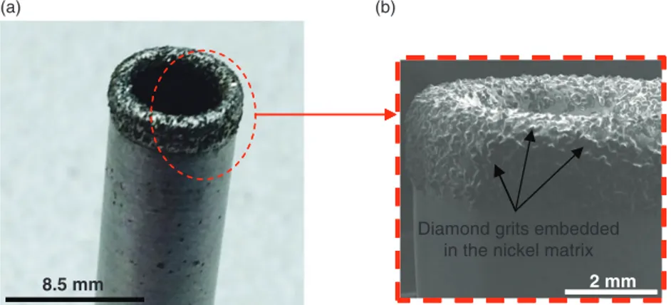
by Saoudi et al.36 and Zitoune and Collombet.41 Foremost, the total thickness of the laminate and the total number of the plies were measured in order to determine the average ply thickness. Consequently, blind holes are obtained using a computer numerical control machine based by controlling the machined depth to obtain one ply, two plies, three plies etc. under the tool (cf. Figure 4(a)). In the present work, drilling was conducted using a core drill with a nominal diameter of 8.5 mm. This core drill is manufactured by Ashai Company and made of electro deposited dia-mond grits (cf. Figure 5). Following the recommenda-tion of Ashai, the core drill used in the current study had an average grit size of 151mm. In addition, the synthetic diamond grits are embedded in a nickel matrix with 50% of crimping rate. The machining par-ameters used for drilling are 0.08 mm/rev feed rate and 8000 r/min spindle speed. These parameters are based on the previous work and yield a machining quality
CFFRP specimeens Core ddrill
CFRP spec (a) (b) i h imens with bl holes 100 mm 60 m lind mm
Figure 4. Specimen preparation for the punching tests. (a) Drilling of the blind holes with CNC machine using core drill. (b) Cutting of the specimens with blind holes using abrasive water jet process.
CNC: computer numerical control.
8.5 mm
(a) (b)
Diamond grits embedded in the nickel matrix
2 mm
Figure 5. Core drill used the preparation of blind holes and the punching tests. (a) Global view carried out by optical microscopy and (b) SEM image of the local view of the active zone.
SEM: scanning electron microscope.
Table 1. Mechanical properties of HexPlyT700-M21-GC.44 Mechanical properties of the materials (T700-M21)
Young’s modulus in the L direction (GPa) Ell¼ 142 Young’s modulus in the T direction (GPa) Ett¼ 8.4
Shear modulus (GPa) Glt¼ 4.5
Poisson’s ratio nlt¼ 0.33
Ply thickness (mm) h¼ 0.26
Fibre content (%) Vf¼ 59
Critical strain energy release rate in mode I (J/m2)
without delamination and fibres pull-out on the wall of the holes.10
For the punching tests, specimens with blind holes are cut from the same mother plate in order to reduce the variability in thickness and mechanical properties due to the manufacturing process.44 These specimens with dimensions of 100( 60 mm were cut using water jet process (cf. Figure 4(b)).
The geometry of the core drill and the machining parameters used for machining and for the punching tests are summarized in Table 2.
The punching tests were conducted on INSTRON traction machine with max loading of 10 kN. During the punching tests, the selected specimens were pos-itioned on two supports and clamped (Figure 6). The punching load was applied at rate of 1 mm/min with the same drill previously used for machining the blind holes. For each configuration of the number of plies under the tool, the test was repeated three times.
Punching load versus drill displacement data was rec-orded by the INSTRON data acquisition system.
X-ray tomography and postmortem observation
If we refer to previous work, the control of the thick-ness of the uncut laminate under the drill remains a challenge due to the inherent variability induced by the manufacturing process of the CFRP lamin-ates.12,21,44 For the quantification of the variability such as the in situ thickness of the uncut laminates of the blind holes, X-ray tomography is conducted on all the specimens prior the punch tests. This method of characterization helps to explain the influence of the variation of the in situ thickness of the CTF after the punching tests. Measurements with X-ray micro-com-puted tomography were carried out using Micro-Tomography Easy Tom 130 machine. Each specimen was exposed to radiation and rotated through 360" to
capture the images for 3D construction (Figure 7). The X-ray voltage and current were set as 130 kV and 300 mA, respectively. X-rays were diverged conically from the source and received by the receiver after encounter-ing the specimen. The specimens of 60 mm width were exposed at a distance of 80 mm to the source. The source has a spot size of 3mm. Each sample was scanned for 70 min with 0.01 s per projection. In this condition of measurement, the maximum possible reso-lution is around 40mm.
Results and discussion
Figure 8 represents the load versus displacement plots obtained during punching tests for different number of plies under the tool (one ply, two plies and three plies). It can be observed that the applied force by the core drill increases linearly till a critical value. This critical value that represents the CTF is strongly influenced by
Figure 6. Drilling fixture of punching tests on quasi-isotropic specimens conducted on universal testing machine.
Figure 7. Tomography view for analyzing specimens before punching tests.
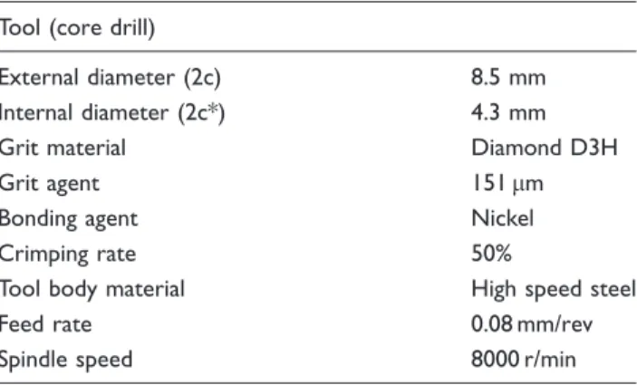
Table 2. Characteristic geometric of the core drill made of diamond grit.
Tool (core drill)
External diameter (2c) 8.5 mm
Internal diameter (2c*) 4.3 mm
Grit material Diamond D3H
Grit agent 151mm
Bonding agent Nickel
Crimping rate 50%
Tool body material High speed steel
Feed rate 0.08 mm/rev
the number of plies under the drill. Thereafter, a sudden reduction of force is observed, which can be explained by the initiation and the propagation of crack. The evolution of the force as a function of the displacement is similar to those observed in the litera-ture for punching tests conducted on twist drills; how-ever, the maximum level of the recorded forces is different.36,41This can be explained by the local contact condition tool/CFRP being different resulting in differ-ent load distributions for a core drill as compared to twist drill.
Figure 9 depicts a comparison between the CTF obtained by the proposed model (assuming an ortho-tropic material, dedicated by the equation (30)), the model proposed in the literature by Hocheng and Tsao24(assuming an isotropic material) and the experi-mental values of the punching tests. From this figure, it
can be confirmed that with increasing the number of plies under the tool (from one ply till three plies), the measured CTF increases by 885%.
As the number of plies under the tool increases, the uncut thickness and bending stiffness increase propor-tionately resulting in higher CTF predictions that match with experimental punching test data. The Hocheng model from literature assuming an isotropic material underestimates the critical values of the CTF. The deviation from experimental data becomes more pronounced for increasing number of uncut plies under the drill. As a matter of fact, the relative devi-ation between the measured values and Hocheng model24 is around 23 and 56% for one ply and three plies under the tool, respectively. In contrast, for the proposed model, the average deviation between the measured values and the predicted CTF is around
0 150 300 450 600 750 900 1050 0 0.2 0.4 0.6 0.8 Lo ad (N ) Displacement (mm) One ply under the tool
Two plies under the tool Three plies under the tool
Figure 8. Punching axial force with different number of plies under the tool.
0 100 200 300 400 500 600 700 800 900 1000 0 0.5 1 1.5 2 2.5 3 3.5 4 C ri ti ca l th ru st f or ce
Number of plies under the tool Hocheng model: isotropic material
Proposed Model: orthotropic material Experimental
Figure 9. Evolution of the critical thrust force for different plies under the tool forb ¼ 0.24 and s ¼ 0.8 (with: c ¼ 4.25 mm, t¼ 1.02 mm and c* ¼ 3.23 mm): Comparison between the experimental values, Hocheng model24and the proposed model.
14 and 23 % when three plies and one ply under the tool is considered, respectively. In fact, the good agree-ment of the CTF observed between the proposed model and the experimental values can be explained by the fact that the proposed model is more representative of the material nature (orthotropic phenomenon).
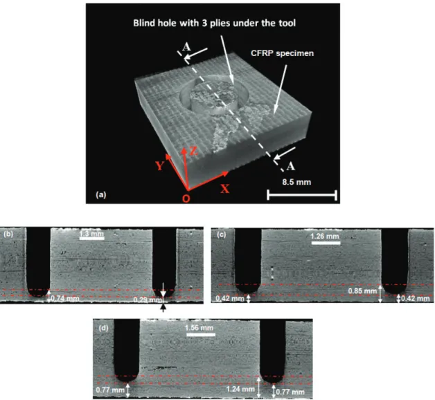
However, the gap observed between the experimen-tal values and the predicted values by the proposed model of the CTF can be explained mainly by the random variation of the ply thickness of the laminates. This explanation is confirmed by the X-ray tomography of the CFRP specimens observed for different uncut plies with blind holes obtained before the punching tests (cf. Figure 10). From these observations, it is clear that the thickness of the uncut part located under the drill for one ply under the tool is around 0.29 mm (Figure 10(b)), which does not correspond to
the theoretical value recommended by the manufac-turer of the prepreg (which is equal to 0.26 mm). Also, in the case of two plies under the tool, the mea-sured uncut thickness is around 0.42 mm which repre-sents a relative deviation of 19% compared to the theoretical value (0.52 mm). In addition, to this vari-ability in the ply thickness due to the process of man-ufacturing of the composite structures,35,36,44the X-ray tomography images reveal that, in the vicinity of the applied loading, the geometry of the blind holes (or the uncut part) does not represent totally a plane surface as is considered in the analytical model. In fact, an over-thickness around of 0.43 mm is observed for all the spe-cimens tested due to the core drill geometry. Otherwise, the postmortem observation conducted by X-ray tom-ography after punching test of some specimens reveals the clear presence of an inter-laminar crack for the
Figure 10. Postmortem observation of the blind holes before the punching tests. (a) 3D image of the CFRP specimen with three plies under the tool with schematic view of the cross section (A-A). (b), (c) and (d) Cross section (A-A) of the specimens with one ply, two plies and three plies under the tool, respectively.
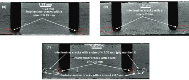
specimens with one and two plies under the tool. These inter-laminar cracks are characterized by a size of 0.95 mm to greater than 2 mm for one ply under the tool and two plies under the tool, respectively (cf. Figure 11(a) and (b)). It is important to mention that the size of the inter-laminar crack used in the ana-lytical model (which is equal to 1 mm) is representative of the crack identified experimentally from the X-ray tomography images. However, for the specimens with three plies under the tool, the postmortem observations reveal the presence of inter-laminar and intra-laminar cracks with a size of 1.33 and 0.4 mm, respectively (cf. Figure 11(c)). From these observations, it can be concluded that the phenomena of the variability described above have an important influence on the initiation as well as on the propagation of the crack.
Additionally, deviation observed between the pre-dicted CTF and the measured values can also be
attributed to: (1) neglecting the effect of bending and stretching coupling that is commonly observed in CFRP and (2) the residual strains due to the curing phase that induces some local deformation in the geom-etry of the blind hole as well as the geomgeom-etry of the core drill which leaves a` footprint different from the one supposed in the analytical model (plane shape).
The uniqueness of the proposed model (equation (30)) for the prediction of the CTF is the fact that it takes into account the tool geometry (internal and external diameters) compared to the other models avail-able in the literature.17,18,20,33–36,38–40 In this context, Figure 12 represents the evolution of CTF with respect to ‘s’ (delamination diameter ratio) for different ratios of ‘b’ (thickness of the core drill) when one ply under the tool is considered. It can be observed from Figure 12 that for a given value of b ¼ 0.2, the critical thrust remains stable (around 18 N) when the
Figure 11. Postmortem observation of the specimens after punching tests. With (a) cross section of specimen with one ply under the tool, (b) cross section of specimen with two plies under the tool and (c) cross section of specimen with three plies under the tool.
delamination ratio varies from 0 to 0.3. However, when the delamination ratio increases from 0.3 till 1, the CTF predicted by the model increases by 188% (from 18 to 52 N when b ¼ 0.2).
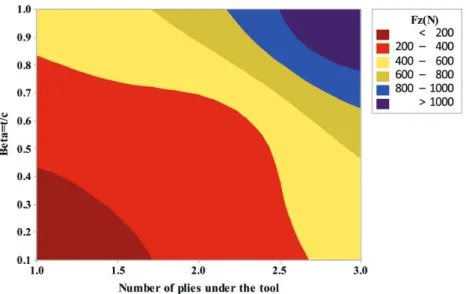
The cartography presented in Figure 13 shows the distribution of the CTF obtained from the equation (30) as a function of b and the number of the plies under the tool. From this cartography, the critical value of the thrust force can be identified for different ratios of the parameterb of the core drill. For example, in the case of the parameters of the core drill presented in Table 2 of the section 3.2 (t¼ 2.1 mm, 2 c ¼ 8.5 mm andb ¼ 0.24), the critical values of the thrust force as a function of the number of plies under the core drill correspond the dashed line on the Figure 13. In this case, a good agreement of the predicted value and the measured value is observed. For other core drill geom-etry, CTF predictions can be used as guideline to pre-vent exit side drilling-induced delamination.
Conclusions
From the present study, a more realistic analytical model for CTF prediction using a core drill has been presented. The originality of this model lies in the use of orthotropic properties for the composite ply as applic-able for drilling of multi-directional composite lamin-ates. The proposed model CTF predictions were compared to those from the literature (with isotropic material property assumptions).24,25The efficacy of the proposed model is further established by comparison of the predicted CTF with push-out experiments com-bined by the postmortem observations making use of X-ray tomography technique conducted before and after the punching tests. From the results of the
proposed model and the experimental tests, the follow-ing conclusions can be drawn:
. From the comparison between the model available in the literature24,25which allows to predict the CTF responsible for delamination at the hole exit during drilling of CFRP using core drill, the proposed model and the measured value of CTF, it is con-firmed that the model proposed by Hocheng and Tsao24underestimated the CTF. The predicted CTF value obtained by the proposed model is in good agreement with the experimental values of the CTF. This explains the importance of choosing appropri-ate mappropri-aterial properties and associappropri-ated mechanical behavior composite laminates that affect stiffness, thereby contributing to CTF predictions.
. By conducting X-ray tomography experiments prior to the punch tests, the uncut laminate thickness was considered as the main factor responsible of the devi-ation observed between the predicted and measured CTF. Indeed, the difference in the thrust force pre-dicted and measured during punching tests can be attributed to the local variation in ply thickness of the laminate due to the manufacturing process of the laminate. In addition, the postmortem observation of the specimens after punching tests reveals the clear presence of an opening crack phenomenon by mode I and some intra-laminar cracks that the model does not take into account.
Declaration of Conflicting Interests
The author(s) declared no potential conflicts of interest with respect to the research, authorship, and/or publication of this article.
Figure 13. Cartography of the critical thrust force (Fz) in function of tool geometry and the number of plies under the tool for delamination ratio (s¼ c/a ¼ 0.8).
Funding
The author(s) received no financial support for the research, authorship, and/or publication of this article.
References
1. Research LM. Growth opportunities in global carbon fiber market, 2015.
2. Gunston B. Airbus: The complete story. 2nd ed. Somerset: Haynes Publishing, 2009.
3. Arul S, Vijayaraghavan L, Malhotra SK, et al. The effect of vibratory drilling on hole quality in polymeric compos-ites. Int J Mach Tool Manufact 2006; 46: 252–259.
4. Krishnamoorthy A, RajendraBoopathy S and
Palanikumar K. Delamination prediction in drilling of CFRP composites using artificial neural network. J Eng Sci Tech 2011; 6: 191–203.
5. Prakash S, Palanikumar K and Krishnamoorthy A. Thrust force evaluation in drilling medium density fibre (MDF) panels using design of experiments. Int J Manuf Tech Manag 2012; 25: 95–112.
6. Zitoune R, Vijayan K, Collombet F, et al. Experimental and numerical analysis on drilling of carbon fibre rein-forced plastic and aluminium stacks. Compos Struct 2016; 146: 148–158.
7. Zitoune R, Krishnaraj V, Almabouacif S, et al. Influence of machining parameters and new nano-coated tool on drilling performance of CFRP/aluminium sandwich. Compos B Eng 2012; 43: 1480–1488.
8. Tsao CC, Kuo KL and Hsu IC. Evaluation of a novel approach to a delamination factor after drilling compos-ite laminates using a core-saw drill. Int J Adv Manuf Tech 2012; 56: 617–622.
9. Karimi NZ, et al. Critical thrust force and feed prediction models in drilling of composite laminates. Compos Struct 2016; 148: 19–26.
10. Cadorin N and Zitoune R. Wear signature on hole defects as a function of cutting tool material for drilling 3D interlock composite. Wear 2015; 332–333: 742–751. 11. Cadorin N, Zitoune R, Seitier P, et al. Analysis of
damage mechanism and tool wear while drilling of 3D woven composite materials using internal and external cutting fluid. J Compos Mater 2015; 49: 2687–2703. 12. Grilo TJ, et al. Experimental delamination analyses of
CFRPs using different drill geometries. Compos B 2013; 45: 1344–1350.
13. Konig W, Wulf C, Gras P, et al. Machining of fibre reinforced plastics. CIRP Ann - Manuf Tech 1985; 34: 537–548.
14. Mohan NS, Ramachandra A and Kulkarni SM. Influence of process parameters on cutting force and torque during drilling of glass-fiber polyester reinforced composites. Compos Struct 2005; 71: 407–413.
15. Shyha IS, Aspinwall DK, Soo SL, et al. Drill geometry and operating effects when cutting small diameter holes in CFRP. Int J Mach Tool Manufact 2009; 49: 1008–1014. 16. Davim JP, Pedro R and Anto´nio CC. Author links open the author workspace. b. Experimental study of drilling of glass fiber reinforced plastics (GFRP) manufactured by hand lay-up. Compos Sci Tech 2004; 64: 289–297.
17. Hocheng H and Tsao CC. Comprehensive analysis of delamination in drilling of composite materials with vari-ous drill bits. J Mater Process Tech 2003; 140: 335–339. 18. Tsao CC and Hocheng H. Taguchi analysis of
delamin-ation associated with various drill bits in drilling of com-posite material. Int J Mach Tool Manufact 2004; 44: 1085–1090.
19. Tsao CC and Hocheng H. Computerized tomography and C-Scan for measuring delamination in the drilling of composite materials using various drills. Int J Mach Tool Manufact 2005; 45: 1282–1287.
20. Hocheng H and Tsao CC. Effects of special drill bits on drilling-induced delamination of composite materials. Int J Mach Tool Manufact 2006; 46: 1403–1416.
21. Faraz A, Biermann D and Weinert K. Cutting edge rounding: an innovative tool wear criterion in drilling CFRP composite laminates. Int J Mach Tool Manufact 2009; 49: 1185–1196.
22. Abrao AM, Rubio JCC, Faria PE, et al. The effect of cutting tool geometry on thrust force and delamination when drilling glass fibre reinforced plastic composite. Mater Des 2008; 29: 508–513.
23. Lazar MB and Xirouchakis P. Experimental analysis of drilling fiber reinforced composites. Int J Mach Tool Manufact 2011; 51: 937–946.
24. Hocheng H and Tsao CC. Analysis of delamination in drilling composite materials using core drill. Australas J Mech Eng 2003; 1: 49–53.
25. Tsao CC and Hocheng H. Effects of exit back-up on delamination in drilling composite materials using a saw drill and a core drill. Int J Mach Tool Manufact 2005; 45: 1261–1270.
26. Saleem M, et al. Role of the surface quality on the mech-anical behavior of CFRP bolted composite joints. Int J Fatig 2015; 80: 246–256.
27. Haddad M, Zitoune R and Bougherara H. Study of trim-ming damages of CFRP structures in function of the machining processes and their impact on the mechanical behavior. Compos B 2014; 57: 136–143.
28. Iliescu D, Gehin D, Gutierrez ME, et al. Modeling and tool wear in drilling of CFRP. Int J Mach Tool Manufact 2010; 50: 204–213.
29. Davim JP. Machining composite materials. New York: Nova Publishers, 2009.
30. Sheikh-Ahmad JY and Shinde SR. Machinability of carbon/epoxy composites by electrical discharge machin-ing. Int J Mach Mach Mater 2016; 18: 3–17.
31. Krishnaraj V, Zitoune R and Davim JP. Drilling of poly-mer-matrix composites. Heidelberg: Springer, 2013. 32. Karimi NZ, et al. Analysis of damage mechanisms in
drilling of composite materials by acoustic emission. Compos Struct 2015; 13: 107–114.
33. Hocheng H and Dharan CKH. Delamination during dril-ling in composite laminates. J Eng Ind 1990; 112: 236–239.
34. Jain S and Yang DCH. Delamination-free drilling of composite laminates. J Eng Ind 1994; 116: 475–481. 35. Saoudi J, Zitoune R, Gururaja S, et al. Prediction of
drilling composite laminates: thermo-mechanical ana-lysis. Int J Mach Mach Mater 2016; 18: 77–98.
36. Saoudi J, et al. Critical thrust force predictions during drilling: analytical modeling and X-ray tomography quantification. Compos Struct 2016; 153: 886–894. 37. Feito N, Lopez-Puente J, Santiuste C, et al. Numerical
prediction of delamination in CFRP drilling. Compos Struct 2014; 108: 677–683.
38. Hocheng H and Tsao CC. The path towards delamina-tion-free drilling of composite materials. J Mater Process Tech 2005; 167: 251–264.
39. Zhang LB, Wang LJ and Liu XY. A mechanical model for predicting critical thrust forces in drilling composite laminates. Proc Inst Mech Eng Part B J Eng Manuf 2001; 215: 135–146.
40. Upadhyay P and Lyons J. On the evaluation of critical thrust for delamination-free drilling of composite lamin-ates. J Reinf Plast Compos 1999; 18: 1287–1303. 41. Zitoune R and Collombet F. Numerical prediction of the
thrust force responsible of delamination during the dril-ling of the long-fibre composite structures. Compos Part A Appl Sci Manuf 2007; 38: 858–866.
42. Gururaja S and Ramulu M. Modified exit-ply delamin-ation model for drilling FRPs. J Compos Mater 2009; 43: 483–500.
43. Timoshenko S and Woinowsky-Krieger S. Theory of plates and shells. 2nd ed. New York: McGraw-Hill, 1959. 44. Collombet F, Mulle M, Grunevald Y, et al. Multiscale method for optimal design of composite structures incor-porating sensors. Solid Mech Its Appl 2006; 135: 141–149.
Appendix
Notation
a radius of the circular crack (mm) A area of the crack (mm2)
c outer radius of the drill (mm) c* inner radius of the drill (mm)
D bending rigidity of the plate (N.mm) D0 stiffness coefficient (N.mm)
Dij coefficients of bending stiffness matrix (N.mm)
E Young’s modulus for an isotropic material Ell Young’s modulus in the L direction (N/mm2)
Ett Young’s modulus in the T direction (N/mm2)
Fc critical thrust force for an isotropic material (N)
F1 thrust force applied over a circular plate with
diameter c (N)
F2 thrust force applied over a circular plate with
diameter c* (N)
FZ global thrust force for an orthotropic material
(N)
FZC global critical thrust force for an orthotropic
material (N)
GI strain energy release rate in mode I (J/mm2)
GIc critical strain energy release rate in mode I
(J/mm2) G1
I strain energy release rate in mode I (J/mm2) of a
plate with diameter c G2
I strain energy release rate in mode I (J/mm2) of a
plate with diameter c* Glt shear modulus (N/mm2)
h ply thickness (mm) H thickness of the plate k1 parameter relating to FZ
k2 parameter relating to FZ
k3 parameter relating to FZ
M flexural rigidity of the plate (N.mm) q lateral uniform load (N/mm2) q1 lateral uniform load relating to q
q2 lateral uniform load relating to q
r radial coordinate (mm) s delamination ratio
t thickness of the drill (mm) U global strain energy (N.mm) U1 strain energy relating to U (N.mm)
U2 strain energy relating to U (N.mm)
Vf fibre volume fraction (%)
W work done by external forces (N.mm)
W1 work of the external forces relating to W
(N.mm)
W2 work of the external forces relating to W
(N.mm)
! ratio between thickness and radius of core drill # polar coordinate
$ Poisson ratio for an isotropic material $lt Poisson ratio in (lt) direction