HAL Id: hal-00972028
https://hal.archives-ouvertes.fr/hal-00972028
Submitted on 3 Apr 2014HAL is a multi-disciplinary open access
archive for the deposit and dissemination of sci-entific research documents, whether they are pub-lished or not. The documents may come from teaching and research institutions in France or abroad, or from public or private research centers.
L’archive ouverte pluridisciplinaire HAL, est destinée au dépôt et à la diffusion de documents scientifiques de niveau recherche, publiés ou non, émanant des établissements d’enseignement et de recherche français ou étrangers, des laboratoires publics ou privés.
Carbon nanotubes grown in situ by a novel catalytic
method
Alain Peigney, Christophe Laurent, F. Dobigeon, Abel Rousset
To cite this version:
Alain Peigney, Christophe Laurent, F. Dobigeon, Abel Rousset. Carbon nanotubes grown in situ by a novel catalytic method. Journal of Materials Research, Cambridge University Press (CUP), 1997, vol. 12, pp. 613-615. �10.1557/JMR.1997.0092�. �hal-00972028�
O
pen
A
rchive
T
OULOUSE
A
rchive
O
uverte (
OATAO
)
OATAO is an open access repository that collects the work of Toulouse researchers and makes it freely available over the web where possible.
This is an author-deposited version published in : http://oatao.univ-toulouse.fr/
Eprints ID : 11205
To link to this article :
DOI:10.1557/JMR.1997.0092
URL :
http://dx.doi.org/10.1557/JMR.1997.0092
To cite this version :
Peigney, Alain and Laurent, Christophe and Dobigeon, F. and
Rousset, Abel Carbon nanotubes grown in situ by a novel catalytic
method. (1997) Journal of Materials Research, vol. 12 (n° 3). pp.
613-615. ISSN 0884-2914
Any correspondance concerning this service should be sent to the repository administrator: [email protected]
Carbon nanotubes grown in situ by a novel catalytic method
A. Peigney, Ch. Laurent, F. Dobigeon, and A. Rousset
Laboratoire de Chimie des Matériaux Inorganiques, ESA CNRS 5070, Université Paul-Sabatier, 31062 Toulouse Cedex, France
Carbon nanotubes can be produced by the catalytic decomposition of hydrocarbons on small metal particles. However, nanotubes are generally produced together with non-tubular filaments and tubes coated by pyrolytic carbon. We propose a novel catalyst method for the in situ production, in a composite powder, of a huge amount of single- and multiwalled carbon nanotubes, having a diameter between 1.5 and 15 nm and arranged in bundles up to 100 mm long. We anticipate that dense materials prepared from such composite powders could have interesting mechanical and physical properties.
Carbon nanotubes,1 which may possess outstanding properties, are currently prepared by arc-discharge. Despite continuous improvements,2–7 this method has a poor selectivity between the different forms of carbon obtained and requires a purification step limiting nanotube yield to about 1%.7 The method of catalytic growth on nanometric metal particles8–11 leads to carbon fibers among which nanotubes may be found together with nontubular filaments and tubes coated by pyrolytic carbon. The minimal tube diameter that can be so achieved is that of the catalytic particle. Several authors12–17 tried to adjust parameters such as the catalyst composition and the reaction atmosphere to maximize the nanotube yield and to minimize the tube diameter. Ivanov et al.16 have reported very small amounts of thin tubes (4 nm), and tubes up to 60 mm long, but they point out that the longest tubes are also the thickest. We propose a novel catalyst method for the in situ production, in a composite powder, of a huge amount of single- and multiwalled carbon nanotubes, having a diameter between 1.5 and 15 nm and arranged in bundles up to 100 mm long.
In earlier works,18–21 we have shown that metal-oxide nanocomposite powders are advantageously prepared by selective reduction in hydrogen of oxide solid solutions. Such powders consist of oxide grains containing a dispersion of metal particles smaller than 10 nm in diameter. Most particles are found inside the oxide matrix grains, but some are located on the surface. It was thought that provided we use a hydrogen-hydrocarbon gas mixture, the in situ reduction of the very homogeneously dispersed surface ferric ions would allow the pristine iron particles obtained to be active at a size adequate for the catalytic growth of nanotubes.
We have prepared the stable α form (corundum) of an Al1.9Fe0.1O3 solid solution by the
CH4). The resulting powder was slightly metallized and observed by scanning electron microscopy
(SEM, JEOL JSM 6400). Transmission electron microscopy observations (TEM, JEOL 2010 operated at 200 kV) were also performed.
The specific surface area of the powder was measured by the Brunauer–Emmett–Teller (BET) method (using Kr adsorption at liquid N2 temperature) before and after reduction and after a
reoxidation treatment in air at 900 °C which eliminates all carbon. The carbon content Cr (2.7 ± 0.1 wt.
%) in the reduced powder was determined by flash combustion.
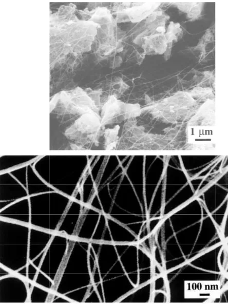
The reduced powder is so densely agglomerated that it retains the shape of the reduction vessel when transferred in a storage box. SEM observations show that the metal-oxide powder grains are uniformly covered by a network of carbon filaments [Fig. 1(a)], which explains the agglomeration state of the material. It is noteworthy that all filaments have a diameter smaller than 100 nm and a length of the order of some tens of micrometers, some having been traced for 100 mm. Note that due to metallization the tubes appear a little bit larger than they actually are. Higher magnification images [Fig. 1(b)] show that the filaments are quite flexible, which suggest they have high mechanical characteristics. The surface of the filaments is free from pyrolytic carbon deposit, and one can also observe extensive branching, showing that most filaments are in fact bundles of much smaller units [Figs. 1(b), 2(a)].
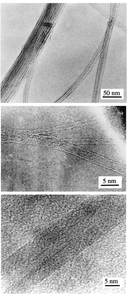
High resolution electron microscopy (HREM) observations show that most filaments are Iijima’s-type nanotubes1 [Figs. 2(b) and 2(c)]. Three single-walled tubes can be seen in Fig. 2( b), the smaller one being only 1.5 nm in diameter, which is well below that reported by other researchers using the catalysis method.15,16 Figure 2(c) shows two superimposed nanotubes with 3 and 16 concentric graphene layers (5 and 15 nm in diameter, respectively). The measured spacing between two layers (0.34 ± 0.01 nm) is that of the d002 distance of graphite. The latter tube is the largest we
have observed. HREM observations also reveal that a few filaments are poorly crystallized. Species such as carbon onions, iron- or iron carbide-filled tubes, and pyrolytic carbon deposit on the outer tube surface are seen occasionally. A graphite deposit a few nanometers thick surrounds the surface iron (or iron carbide) particles.
The particular microstructure consisting of nanotubes that form bundles, which in turn are organized into larger bundles, has been reported by others.6,7,22,23 According to Ebbesen et al.,7,22 bundle formation could explain the high yield of nanotubes by some templating effect. Considering that all tubes in a bundle are about the same length, we estimate that our nanotubes have an aspect ratio in the 1000–10,000 range, which is much higher than previously reported.7
The specific surface area of the powder before and after reduction is 5.03 ± 0.05 m²/g and 11.3 ± 0.1 m²/g, respectively. Such an increase is clearly connected to the presence of carbon filaments in the reduced powder. After carbon elimination by air treatment at 900 °C, a value similar to the initial one is measured (5.13 ± 0.05 m²/g). If one neglects the surface area provided by carbon species other than filaments, as suggested by electron microscopy observations, the total length of the bundles in a
gram of composite powder can be derived from these measurements; indeed, assuming that all bundles are made up of seven perfectly aligned nanotubes, one of them being surrounded by the other ones as in close-packing and considering a tube diameter of, say, 5 nm, the increase ∆S = 6.2 ± 0.2 m²/g after reduction would correspond to a total bundle length of about 100,000 km in a gram of powder.
Considering that ∆S/Cr represents the specific surface area of the bundles, a figure of 230 ± 15
m²/g is found, which is similar to that reported for nanofibers.14 The nanotube specific surface area calculated from this bundle specific surface area is equal to 400 m²/g. This value corresponds to closed nanotubes made up of four concentric graphene layers and 5 nm in diameter, which is in good qualitative agreement with our microscopy observations.
The metal particles obtained from the reduction of a solid solution prove to be much more selective for the formation of long Iijima’s-type carbon nanotubes than metal particles derived from impregnation or evaporation. The reduction of oxide solid solutions in a hydrogen-hydrocarbon atmosphere allows for the preparation of a homogeneous web-like distribution of bundles of carbon nanotubes around the metal-oxide grains. We infer that, owing to the difficulty of manipulating carbon nanotubes, only the in situ growth of nanotubes can lead to such a microstructure. We anticipate that dense materials prepared from such composite powders could have interesting mechanical and physical properties.
FIG. 1. Scanning electron microg alumina grains by carbon filament
rographs of the composite powder. (a) Uniform c ents. (b) Higher magnification image showing clea
coverage of the iron-ean, flexible bundles.
FIG. 2. Transmission electron micrographs of the composite powder. (a) Merging of nanotubes into bundles. (b) HREM image showing a bundle of three single tubes. (c) HREM image showing two superimposed, well-crystallized nanotubes.
REFERENCES
1. S. Iijima, Nature (London) 354, 56–58 (1991).
2. T. W. Ebbesen and P. M. Ajayan, Nature (London) 358, 220–222 (1992).
3. T. W. Ebbesen, P. M. Ajayan, H. Hiura, and K. Tanigaki, Nature (London) 367, 519 (1992). 4. S. Iijima and T. Ichihashi, Nature (London) 363, 603–605 (1993).
5. D. S. Bethune, C. H. Kiang, M. S. de Vries, G. Gorman, R. Savoy, J. Vasquez, and R. Beyers, Nature (London) 363, 605–607 (1993).
6. S. Seraphin and D. Zhou, Appl. Phys. Lett. 64, 2087 –2089 (1994). 7. T. W. Ebbesen, Annu. Rev. Mater. Sci. 24, 235–264 (1994).
8. R. T. K. Baker, P. S. Harris, R. B. Thomas, and R. J. Waite, J. Catal. 30, 86–95 (1973). 9. R. T. K. Baker, P. S. Harris, and S. Terry, Nature (London) 253, 37 –39 (1975). 10. A. Oberlin, M. Endo, and T. Koyama, J. Cryst. Growth 32, 335–349 (1976). 11. G. G. Tibbetts, J. Cryst. Growth 66, 632–638 (1984).
12. R. T. K. Baker and N. M. Rodriguez, in Synthesis and Processing of Ceramics: Scientific Issues, edited by W. E. Rhine, T. M. Shaw, R. J. Gottschall, and Y. Chen (Mater. Res. Soc. Symp. Proc. 349, Pittsburgh, PA, 1994), pp. 251–256.
13. F. Benissad, P. Gadelle, M. Coulon, and L. Bonnetain, Carbon 26, 61–69 (1988). 14. N. M. Rodriguez, J. Mater. Res. 8, 3233–3250 (1993).
15. M. José-Yacaman, M. Miki-Yoshida, L. Rendon, and J. G. Santiesteban, Appl. Phys. Lett. 62, 657–660 (1993).
16. V. Ivanov, A. Fonseca, J. B. Nagy, A. Lucas, P. Lambin, D. Bernaerts, and X. B. Zhang, Carbon 33, 1727 – 1738 (1995).
17. M. Endo, K. Takeuchi, K. Kobori, K. Takahashi, H. W. Kroto, and A. Sarkar, Carbon 33, 873–881 (1995). 18. X. Devaux, Ch. Laurent, M. Brieu, and A. Rousset, J. All. Comp. 188, 179–181 (1992).
19. X. Devaux, Ch. Laurent, and A. Rousset, Nanostruct. Mater. 2, 339–346 (1993).
20. Ch. Laurent, Ch. Blaszczyk, M. Brieu, and A. Rousset, Nanostruct. Mater. 6, 317–320 (1995). 21. Ch. Laurent and A. Rousset, Key Eng. Mater. 108–110, 405–422 (1995).
22. T. W. Ebbesen, H. Hiura, J. Fujita, Y. Ochiai, S. Matsui, and K. Tanigaki, Chem. Phys. Lett. 209, 83 –90 (1993).
23. M. Ge and K. Sattler, in Synthesis and Processing of Ceramics: Scientific Issues, edited by W. E. Rhine, T. M. Shaw, R. J. Gottschall, and Y. Chen (Mater. Res. Soc. Symp. Proc. 349, Pittsburgh, PA, 1994), pp. 313–317.