HAL Id: tel-03149063
https://pastel.archives-ouvertes.fr/tel-03149063
Submitted on 22 Feb 2021HAL is a multi-disciplinary open access
archive for the deposit and dissemination of sci-entific research documents, whether they are pub-lished or not. The documents may come from teaching and research institutions in France or abroad, or from public or private research centers.
L’archive ouverte pluridisciplinaire HAL, est destinée au dépôt et à la diffusion de documents scientifiques de niveau recherche, publiés ou non, émanant des établissements d’enseignement et de recherche français ou étrangers, des laboratoires publics ou privés.
Giorgia Scetta
To cite this version:
Giorgia Scetta. Fatigue cracking of thermoplastic elastomers. Polymers. Université Paris sciences et lettres, 2020. English. �NNT : 2020UPSLS022�. �tel-03149063�
Industrielles de la ville de Paris (ESPCI Paris)
Dans le cadre d’une cotutelle avec Laboratoire de recherches et
de contrôle du caoutchouc et des plastiques (LRCCP)
Fatigue cracking of Thermoplastic Elastomers
Fissuration en fatigue des élastomères thermoplastiques
Soutenue par
Giorgia SCETTA
Le 16 décembre 2020Ecole doctorale n° ED 397
Physique et chimie des
matériaux
Spécialité
Chimie des Matériaux
Composition du jury :
Damien, VANDEMBROUCQ
Directeur de recherche, Président ESPCI, Paris, CNRS
Catherine, GAUTHIER
Professeure, Rapportrice Michelin, LaDoux
Yann, MARCO
Professeur Associé, Rapporteur ENSTA, Bretagne
Michelle, SEITZ
Ingénieure de Recherche, Examinatrice DSM
Costantino, CRETON
Directeur de recherche, Directeur de thèse ESPCI, Paris, CNRS
Matteo, CICCOTTI
Professeur, Co-Directeur
ESPCI, Paris
Patrick, HEUILLET
At the end of this journey, I really want to express my gratitude for the people who helped and supported me in the process of finding the story behind the data. Some of them contributed in a practical way, helping me with the experiments, data interpretation and fruitful discussion, others contributed in an emotional way. All of them feel to me equally important.
I want to thank my professors, Costantino and Matteo for having attempted to teach me (time will say if I learnt!) how to look into scientific problems and for their effort to constantly bring me back on track when I moved on the wrong road.
I want to thank Gabriel Sanoja for his wisdom in science and in life (and for the best homemade pesto I’ve tried!), my wonderful labmates: Juliette, Mehdi and Milena for their friendship and for cuddling me always as the “little-one” of the group.
My gratitude goes to Eric Eucheler, Jianzhu Ju, Bruno Bresson , Josh Yeh and Helen Minsky for their help with experiments and data interpretation.
A big thank also to Francisco, Yinjun, Louis, Pierre, Valentine and all colleagues from SIMM lab who added a great emotional value to these three years.
Last but not least, I want to thank my family for supporting me in every decision and my boyfriend Luca, for all the laughter, the discoveries and especially for understanding me and my unusual, but "happy-togetheeer", vision of life.
Thank you to all of those who contribute to this work.
17
Les élastomères de polyuréthane thermoplastiques (TPU) sont une classe très versatile de polymères qui trouvent de nombreuses applications en raison d'une combinaison de propriétés thermiques et mécaniques. L’élevée extensibilité, l’élasticité réversible et une dureté réglable rendent les TPU comparables á les élastomères classiques à réticulation chimique et conviennent aux « applications de type caoutchouc» telles que les câbles, les ceintures et les chaussures pour n'en nommer que quelques-uns. Toutefois dans un certain nombre d’applications la facilité de mise en œuvre et les possibilités de recyclage des TPE les ont imposés comme une alternative aux élastomères traditionnels. Dans beaucoup de ces applications, la durabilité et la résistance à la fatigue jouent un rôle essentiel et sont considérées comme l'un des facteurs les plus importants pour éviter une défaillance inattendue du composant. La fatigue cyclique et la fracture ont été largement étudiées pour les caoutchoucs, mais c’est beaucoup moins le cas pour le TPU.
En effet si les élastomères vulcanisés sont très majoritairement des matériaux élastiques avec une déformation résiduelle quasi nulle, les élastomères thermoplastiques ont souvent :
- Un niveau d’extensibilité supérieur
- Une résistance au fluage nettement plus faible
- Une certaine déformation plastique en plus de la déformation élastique - Modification de la structure locale avec la déformation
Dans cette thèse deux questions principaux ont été considéré :
1) Comment tenir compte du caractère anélastique des TPU pour évaluer leur résistance á la fatigue : Comment définir G (le taux de restitution d’énergie élastique)pour un matériau qui flue ? Comment tenir compte de la déformation plastic pendant les essais cyclique ?
2) Quel rôle est rôle joué par la morphologie à phases séparées : peut-il expliquer la remarquable résistance à la fatigue cyclique du TPU ? Quel est l’effet du gradient de déformation généré par la présence de la fissure sur la morphologie finale du TPU ?
18
Dans le cadre de cette thèse, on a utilisé trois TPU fourni par la société BASF. Les matériaux sont choisis en raison de leur aptitude à remplacer les élastomères chargés traditionnelles tous avec un module de Young <10MPa. Tous les TPU contiennent une fraction de segment dur et des modules linéaires similaires, mais des compositions des propriétés á grand déformation différentes. TPU_SOFT, que présent une petite quantité de polybutylène téréphtalate cristallisé (PBT), a un écrouissage sous contrainte considérablement moins intense avant la fracture, tandis que les deux autres (TPU_HARD et TPU_XTAL) ont un écrouissage remarquable que seulement pour TPU_XTAL est en partie attribué à la cristallisation sous contrainte (Error! Reference source not found.). Le comportement mécanique des TPU a été, dans le cadre de cette thèse, souvent compare avec celui des trois mélange styrène-butadiène (SBR) avec module de Young similaire (Figure 1(b)). Les donnes sur les SBR sont pris par le travail de recherche de Sami Mzabi(Mzabi, 2010).
(a) (b)
Figure 1 Réponse mécanique des trois TPU (a). Réponse mécanique des trois SBR(Mzabi, 2010)(b)
---
Les sujets principaux de cette thèse ont été abordé dans quatre chapitres expérimentaux organisés en articles scientifiques indépendants.
19
cyclique dans le caoutchouc styrène-butadiène (SBR).
Pour commencer il est logique, pour avoir un point de départ solide, de se demander ce qui contrôle la résistance à la fatigue dans les élastomères traditionnelles, mieux connu que les TPU. Dans ce chapitre nous avons caractérisé la région fortement déformée développée au fond de fissure pendant la fatigue cyclique de trois SBR renforcé avec du noir de carbone (CB). En particulier, nous nous sommes concentrés sur la forme et les processus qui se déroulent au fond de fissure pour compléter et enrichir l'analyse présentée dans notre précédent(Mzabi et al., 2011)
À l'aide d'une caméra infrarouge, nous avons démontré que la présence de charge contrôle principalement l'élévation de température dans le bulk tandis que la densité de réticulation contrôle l'étendue de la concentration de déformation au fond de fissure. Nous avons proposé que le taux de propagation de fissure dc / dn soit probablement contrôlé par une combinaison de dissipation en bulk (reliant le G appliqué à l'énergie locale disponible pour la croissance de la fissure et l'étirement maximal au fond de fissure λmax) et le rapport entre λmax et l'extensibilité limitante des chaînes polymères (contrôlée
par la densité de réticulation et la teneur en charge grâce à l'effet d'amplification des déformations).
2.Definition de la méthode de fatigue pour les élastomères thermoplastiques souple.
Une des méthodes plus utilisées pour caractériser la résistance à la fatigue des élastomères classiques à réticulation chimique est la méthode de propagation de fissure qui suppose que des microfissures existent dans l’échantillon neuf et que la durée de vie est contrôlée par la vitesse de propagation de ces microfissures. L’avancement de cette fissure par cycle appliqué est caractérisé en fonction de taux de restitution d’énergie élastique G.
On a montré que, lorsque les TPU sont chargés cycliquement jusqu'à la même valeur d'étirement maximal, la courbe de tension-étirement (et donc G(𝜆𝜆𝑚𝑚𝑚𝑚𝑚𝑚)) change avec le nombre de cycles appliqués, mais atteint finalement un état stationnaire après 10.000 cycles(Figure 2). Nous proposons une méthodologie appropriée pour évaluer la résistance à la fatigue cyclique dans les TPU, basée sur une approche de la mécanique de
20
élevée au fluage des TPU que les élastomères traditionnels. En comparant les résultats obtenus du TPU avec ceux des élastomères chargés classiques avec un module linéaire similaire, nous soulignons l'excellente ténacité et la résistance à la fatigue cyclique des TPU.
Figure 2 G en fonction du nombre de cycles pour la même valeur d'étirement maximal
3.Proprietés mécaniques des matériaux et rhéodurcissement local
Dans ce chapitre, on a étudié le comportement mécanique cyclique en tension uniaxiale des trois TPU. Malgré les différences á large déformation parmi les trois TPUs, les résultats des tests cycliques en traction uniaxialemontrent que les trois TPU présents des propriétés similaires :
• Grande hystérésis entre le premier cycle de chargement-déchargement (effet Mullins)
• Une déformation résiduelle marquée λres après déchargement.
• L’augmentation du module de Young a petite déformation après le chargement cyclique á des valeurs de déformation croissantes (Figure 3).
En particulier, le raidissement du TPU résultant d'un chargement cyclique est fondamentalement différent du ramollissement (également appelé dommage cyclique) typiquement observé dans les caoutchoucs chargés réticulés chimiquement et provient de la fragmentation du HD d'origine en sous-unités plus petites mais plus nombreuses
21
supplémentaires.
Figure 3 Young Modulus VS Hencky Strain pour les trois TPUs .
Nous proposons que ce renforcement causé par la déformation plastique, puisse jouer un rôle analogue à la cristallisation induite par déformation observée dans le caoutchouc naturel étiré, mais avec un caractère persistant. Il peut provoquer un renforcement local où un champ de déformation non homogène est présent, comme c'est le cas par exemple à la pointe d'une fissure se propageant en fatigue cyclique, fournissant une explication potentielle de la ténacité et de la résistance à l'usure bien connues du TPU.
22
microstructure á l’échelle local
L’élevé résistance à la fatigue pour les trois TPU associé á l'absence de charges inorganiques et de réticulations chimiques (qui jouent un rôle dans la détermination de la résistance à la fatigue des élastomères) rend intéressant de réaliser une corrélation directe entre les propriétés mécaniques du caoutchouc et des TPU, et ouvre la question du rôle joué par la morphologie à phases séparées des TPU. En utilisant la corrélation d'image numérique (DIC) et la diffraction des rayons X in situ (SAXS et WAXD), nous avons caractérisé la région de forte déformation avant le fond de fissure dans les deux TPU, avant et après la fatigue cyclique. On a proposé que la localisation de la déformation et la structure anisotrope trouvée au fond de fissure dans les TPU après fatigue cyclique est liées à la restructuration locale des domaines durs qui, induit une rigidité plus élevée dans la région entourant la fissure. Nous proposons que cette variation spatiale des propriétés mécaniques réduit la concentration de déformation dans les cycles suivants, protégeant ainsi le fond de fissure des valeurs élevées de déformation et réduisant la probabilité de scission de la liaison à chaque cycle de chargement, expliquant ainsi la remarquable résistance à la fatigue cyclique des TPU.
PART I
1 INTRODUCTION AND CHAPTERS ORGANIZATION ... 1-3
1.1INDUSTRIAL CONTEXT AND SCIENTIFIC QUESTION OF THE STUDY ... 1-3
1.2ORGANIZATION OF THE STUDY ... 1-4
1.3NOTE ON THE ADOPTED NOMENCLATURE ... 1-5
1.4REFERENCES ... 1-7
2 ELASTOMERS ... 2-10
2.1MAIN PROPERTIES OF ELASTOMER ... 2-10
2.2DEFINITION OF ENTROPIC RUBBER ELASTICITY ... 2-11
2.3STATISTICAL THEORY ... 2-11
2.4VISCOELASTIC BEHAVIOUR OF ELASTOMERS ... 2-14
2.5REFERENCES ... 2-16
3 FILLED RUBBERS ... 3-17
3.1POLYMER MATRIX:SBR ... 3-18
3.2VULCANIZATION ... 3-18
3.3FILLER SYSTEM ... 3-19
3.4DISSIPATIVE MECHANISMS IN FILLED RUBBERS ... 3-22
3.5STRAIN INDUCED CRYSTALLIZATION ... 3-25
3.6NANO-CAVITATION ... 3-26
3.7CONCLUDING REMARKS ... 3-27
3.8REFERENCES ... 3-28
4 THERMOPLASTIC ELASTOMERS ... 4-33
4.1HISTORICAL SURVEY AND GENERIC CLASSIFICATION ... 4-34
4.2MORPHOLOGY OF TPU ... 4-37
4.3THERMODYNAMIC OF PHASE SEPARATION ... 4-38
4.6CONCLUDING REMARKS ... 4-46
4.7REFERENCES ... 4-48
5 FRACTURE AND FATIGUE IN SOFT MATERIALS ... 5-53
5.1BRIEF INTRODUCTION TO LINEAR ELASTIC FRACTURE MECHANIC ... 5-53
5.2FROM LEFM TO FRACTURE MECHANIC OF SOFT MATERIALS ... 5-54
5.3CYCLIC FATIGUE ... 5-59
5.4STRATEGY TO IMPROVE FATIGUE RESISTANCE IN SOFT MATERIALS ... 5-62
5.5CONCLUDING REMARKS ... 5-64
5.6REFERENCES ... 5-65
PART II
6 CYCLIC FATIGUE IN SBR: THE ROLE OF CRACK TIP ... 6-71
6.1ABSTRACT ... 6-72
6.2INTRODUCTION ... 6-72
6.3MATERIALS AND METHODS... 6-74
6.4RESULTS ... 6-76
6.5CYCLIC FATIGUE TESTS ... 6-78
6.6MULTI-SCALE CRACK TIP OBSERVATION ... 6-82
6.7EXTENDED DISCUSSION ... 6-86
6.8CONCLUSIONS ... 6-90
6.9SUPPLEMENTARY INFORMATION ... 6-90
6.10ACKNOWLEDGEMENTS ... 6-91
6.11REFERENCES ... 6-91
7 CYCLIC FATIGUE FAILURE OF TPU ... 7-95
7.1ABSTRACT ... 7-96
7.2INTRODUCTION ... 7-96
7.3MATERIALS AND METHODS ... 7-102
7.6CONCLUSION ... 7-115
7.7ACKNOWLEDGEMENTS ... 7-116
7.8REFERENCES ... 7-117
8 MECHANICAL PROPERTIES OF SOFT TPU AND STRAIN INDUCED STRENGTHENING ... 8-121
8.1ABSTRACT ... 8-122
8.2INTRODUCTION ... 8-123
8.3MATERIALS AND METHODS ... 8-124
8.4MECHANICAL TESTING AND STRUCTURAL INVESTIGATIONS ... 8-129
8.5DAMAGE ANALYSIS IN CYCLIC LOADING ... 8-136
8.6DISCUSSION ON THE DIFFERENCES BETWEEN TPU AND SBR ... 8-141
8.7CONCLUSIONS ... 8-142
8.8ACKNOWLEDGEMENTS ... 8-143
8.9REFERENCES ... 8-144
9 SELF-ORGANIZATION AT THE CRACK TIP AND CYCLIC FATIGUE IN TPU ... 9-147
9.1ABSTRACT ... 9-148
9.2INTRODUCTION ... 9-149
9.3MATERIALS AND METHODS: ... 9-150
9.4RESULTS ... 9-155
9.5DIFFERENCES BETWEEN MICROSTRUCTURE AT BULK AND CRACK TIP ... 9-162
9.6DISCUSSION ... 9-167
9.7CONCLUSION ... 9-171
9.8ACKNOWLEDGMENTS ... 9-172
9.1X-RAY ANALYSIS ... 9-177
9.2STRAIN-INDUCED STRUCTURAL CHANGES ... 9-180
9.3RESIDUAL CRYSTALLINITY IN UNIAXIAL STRAINED TPU_XTAL ... 9-181
9.4CYCLIC FATIGUE METHOD B ... 9-181
10 GENERAL CONCLUSION AND PROSPECTS... 10-185
10.1FINAL REMARKS AND FUTURE PERSPECTIVES ... 10-188
10.2REFERENCES ... 10-189
ANNEXES ... 191
1. FTIR ANALYSIS ... 191
2. TOUGHNESS: EFFECT OF TEMPERATURE AND STRAIN RATE ... 193
1.1EXPERIMENTAL CONDITIONS ... 193
3. CRACK EXTENSION AND BLUNTING AT HIGH STRETCH RATE ... 194
4. CREEP AND STRESS RELAXATION ... 197
CB Carbon Black
SBR Styrene-Butadiene Rubber TPE Thermoplastic elastomer
TPU Thermoplastic polyurethane elastomer PBT Polybutylene terephthalate
SIC Strain induced crystallization HD Hard domain
SS Soft Domain HS Hard segment PS Pure Shear Geometry
DSC Differential scanning calorimetry DIC Digital image correalation
SAXS Small Angle X-Ray Scattering WAXD Wide Angle X-Ray Scattering DMA Dynamic Mechanical Analysis FTIR Fourier Transformed Infrared Spectroscopy
Part I
1-3
1 I
NTRODUCTION AND
CHAPTERS ORGANIZATION
1.1 Industrial context and scientific question of the study
Thermoplastic elastomers (TPE) made their appearance on the market “only” at the middle of last century and since then they saw a rapid development, especially because of their fast processability and adjustable mechanical properties. Among all TPE, the class of thermoplastic polyurethane elastomers (TPU) is very promising, especially because TPU can mimic some properties of common thermoset elastomers (such as high reversible stretchability and low Young modulus <10 MPa), coupled with an excellent abrasion resistance, and simultaneously offering the outstanding advantage of an easier processability and recyclability.
Sportwear industry (footwear, waterproof gloves, breathable socks), automotive (scratch bumper protection) and the medical sector (eco-friendly alternative to the commonly used polyvinyl chloride or PVC) are only some examples of TPU applications.
Figure 1-1 Example of TPU's applications
1-4
Coupled with the demand of TPU products has also grown the necessity of finding suitable testing procedures to implement safe design and predicting durability of this class of materials, especially in dynamic applications which often require to operate under repeated cyclic conditions.
Following the industrial trend, it is not surprising that the laboratory of research and control of caoutchouc and plastics (LRCCP) has witnessed an increasing demand for TPUs durability and fatigue characterization, which motivated the original objective of this work: the definition of a suitable methodology to assess cyclic fatigue resistance of TPUs.
At the same time, the limited understanding of TPU fracture mechanisms and the recurrent comparison between TPU and thermoset rubbers (despite their different molecular architecture), rapidly encouraged our interest toward the more fundamental research aspects of elucidating the crack propagation mechanisms operating in soft TPUs and how different they are compared to thermoset elastomers.
1.2 Organization of the study
This thesis was mainly structured in two parts. The first part is divided in four chapters and provides an extended introduction on the state of the art concerning the main topics treated in this work: elasticity and viscoelasticity, rubber and TPU, fracture mechanics and cyclic fatigue. The second part is divided in four chapters organised as independent scientific articles.
Part I: extended introduction
Chapter 1 deals with the general concept of entropic elasticity and introduces the concept of viscoelasticity that will be further discussed in the Part II.
Chapter 2 rapidly describes the filled rubber system that is the main subject of the Chapter 6 and is often used as a benchmark to compare the mechanical and fatigue behavior of TPU. Chapter 3 starts with an extended introduction to the generic class of thermoplastic elastomers and then moves specifically to the sub-class of thermoplastic polyurethane elastomers. The second part of the chapter provides a summary of the state of the art for strain-induced structure modification of TPUs needed to address the issue of morphological changes near the crack tip in TPUs explained in Chapter 9.
1-5
Chapter 4 addresses the topic of fracture mechanics applied to elastomers. It briefly recalls the main methodologies adopted to evaluate cyclic fatigue resistance in elastomers and introduces some recent methodologies implemented to increase cyclic fatigue resistance in different soft materials.
Part II: four chapters in form of scientific articles
The first article (Chapter 6) focuses on the effect of heat dissipation in cyclic fatigue for different filled and crosslinked rubbers. This paper reanalyses some of the work carried out by Mzabi et. al on the characterization of the crack tip under cyclic loading for filled SBR. All the relevant data are taken from the PhD work of Mzabi 1,2.
The second article (Chapter 7) aims to define a suitable procedure to evaluate cyclic fatigue in TPU. We critically review some important aspects regarding the choice of methodology such as the achievement of steady state and definition of the cyclic loading conditions.
The third article (Chapter 8) represents a comprehensive mechanical characterization of the cyclic behaviour for three commercial TPU with similar linear properties but different large strain behaviours. We discuss the concept of cyclic strain-induced damage and energy dissipation.
The fourth article (Chapter 9) is focused on cyclic fatigue results in two commercial TPUs at different testing temperature. Using X-ray and digital image correlation (DIC), we discuss the effect of crack in structural modification on TPU that in turn, affects their fatigue resistance in cyclic conditions.
1.3 Note on the adopted nomenclature and materials
In the present work we used two kinds of material: styrene-butadiene rubber (SBR) and TPU. All the data for SBR are taken from Mzabi2. The original samples were prepared moulded and
cured by Michelin. All TPUs were provided by BASF and injected by LRCCP.
We decided to organize this work in four scientific articles thus, the specific composition will be separately reported in the “materials section” of each chapter (or article), consistently with the materials considered in the chapter.
1-6
To ensure an smooth readability of this manuscript, we briefly report here the basic nomenclature adopted for all materials.
The typical SBR will be label as: 20CB_8XL
CB indicates the presence of carbon black preceded by the percentage of the filler volume
fraction (20% in the example) . XL refers to the crosslinking density and is preceded by the crosslinking density expressed in [10-5 mol/cm3] (8∙10-5 mol/cm3 in the example).
The three commercial TPUs on the other side, have been chosen based on their low Young modulus (<10MPa) which is very similar for all of them, and their large strain behaviour which is different one from another. To remark this aspect, we always report the commercial name of each TPU in the material section but we refer to them with the following names:
565 A 12P = TPU_ XTAL, where XTAL indicates the presence of strain hardening behaviour
in the stress-stretch uniaxial curve with strain induced crystallization (SIC).
EC 60 A 10P= TPU_HARD, where HARD indicates the presence of strain hardening
behaviour but without SIC. (Note that in Chapter 7 TPU_HARD will be simply referred as TPU to underline the differences with generic vulcanised rubbers)
LP 9277 10=TPU_SOFT, where SOFT indicates a softer behaviour at large strain compared
1-7
1.4 References
1. Mzabi S, Berghezan D, Roux S, Hild F, Creton C. A critical local energy release rate criterion for fatigue fracture of elastomers. J Polym Sci Part B Polym Phys. 2011;49(21):1518-1524. doi:10.1002/polb.22338
2. Mzabi S. Caractérisation et analyse des mécanismes de fracture en fatigue des élastomères chargés. 2010:1-310.
2-9
2 E
LASTOMERS
Elastomers are polymeric materials which can be highly deformed by weak stress and return to their initial shape when the stress is removed. They generally are amorphous polymer composed by long and flexible macromolecules above their glass transition that in principle, makes elastomers analogous to a viscous liquid. Anyway, when these long molecules are sparsely chemically or physically bonded (crosslinked) together at relatively large distance they behave as a solid 1.
There are two main kinds of elastomers: thermoset and thermoplastic elastomers. Thermoset elastomers, often generically referred to as rubbers, are characterised by the presence of chemical bonds between polymer chains. They can be swollen into solvents but are generally insoluble. In thermoplastic elastomers, on the other hand, the spontaneous phase segregation and re-arrangement of hard domains generates physical (and reversible) crosslinking. They are generally soluble in solvents and have less temperature stability2.
2.1 Main properties of elastomer
Elastomers are generally characterised by low tensile moduli (1-10MPa) , high extensibility , low permeability and electrical insulation 3. They are used in several
applications including sealant, tyres, vibration and corrosion protection, conveyor belts etc.
2-10
The main physical requirements for a polymer to show elastomeric properties are summarized by Treloar 4:
• Long polymeric chains having a high degree of flexibility and mobility (glass transition temperature (Tg) must be below the operation temperature of the
material).
• High molecular weight of the chains favouring the formation of entanglements among the molecules joining them together in a network structure.
• Random coil conformation in relaxed condition.
2.2 Definition of entropic rubber elasticity
In elastomeric polymers macro-molecules change their shape quickly and continuously at normal temperature by Brownian motion assuming random conformation5. When a
perturbation is applied, as an external stress, polymer chains uncoil and begin to align into a more ordered state with correspondingly lower entropy. The driving force of the elastic recovery is therefore of entropic origin (not internal bond origin as enthalpic solid) since the material tends to return to its minimum free energy state by increasing the entropy level. An additional condition is that the polymer must be able to store deformation energy when strained without an excessive viscous flow of the chains. When chains flow the elastomers can retrieve its high entropy state of coiled conformation but it will not exhibit any elastic recovery after the application of the load (Figure 2-1). The introduction of chemical or physical reticulation points hinders viscous flow and ensure elastic behaviour.
2-11
Figure 2‐1 Schematic representation of application and removal of an external load in an un‐crosslinked (up) and crosslinked elastomer (down)
2.3 Statistical theory
One of the simplest models to describe rubber elasticity of a polymer network is the affine model originally proposed by Kuhn and developed by Wall , Flory, James and Guth and accurately described by Treloar4. The two main assumptions are: the affine model and
the Gaussian statistics of the polymer chains. The first implies that the deformation of each network strand is identical to the deformation of the macroscopic solid. The Gaussian assumption considers the entropy of the network as the sum of the entropies od individual chains and can be described by Gaussian statistics. Furthermore, the network is considered ideal so that enthalpic force are neglected (fH=0) , the volume
change is equal to zero, the chains are flexible (T>Tg) and there is no chain slip or strain
induced crystallization. The entropy of a single chain with n links of equal length l with completely random orientation within the chain, can be expressed as
𝒔 𝒄 𝒌𝒃𝟐𝒓𝟐 Equation 2‐1
Where, c is an arbitrary constant with no physical meaning, 𝑏 𝑛𝑙 (function of chain length) and r is the end-to-end distance of the chain. Within the limit of the model assumption, given Li0 the polymer network dimension in the -i direction in the
2-12
undeformed state. If the network is deformed by the factor i the dimension on the
deformed network is described as:
Li= i*Li0 Equation 2‐2
If each network strand is composed by N monomers and both end of the strands are deformed affinely to the macroscopic network, we can define the initial end-to-end vector R0 and the projections along the -i direction of the deformed R as :
ri = iri0 Equation 2‐3
For an ideal network, in absence of any enthalpic contributions (which means that the presence of crosslinking is ignored), the total Helmholtz free energy of the system can be written as W=-T S. Where S is given by the sum of the N single chain entropy difference between the undeformed and deformed state: Ss.
Combining Equation 2-3 and Equation 2-1 the total work of deformation or, elastically stored energy per unit volume W takes the form:
W= 𝑮
𝟐 𝝀𝒙𝟐 𝝀𝒚𝟐 𝝀𝒛𝟐 𝟑 Equation 2‐4
And the shear modulus 𝐺 can be expressed for as:
𝑮 𝟏
𝟐𝑵𝒌𝑻
𝝆𝑹𝑻
𝑴𝟎𝑵𝒄 Equation 2‐5
where is the density of the rubber, R the gas constant , M0 the molecular weight of the
monomer and 𝑁 the number of monomers per elastic strands, i.e. between crosslink points. Equation 2-4 is the fundamental expression defining the elastic properties of rubbers in the Gaussian approximation regime and has the huge advantage to enable the derivation of the stress-strain relationship for any type of applied strain. Additionally, it involves only a single physical parameter or elastic constant: G which contains the dependence of the materials structure. Equation 2-4 indicates that, as far as the Gaussian approach is valid, the elastic response of the rubber is independent of the chemistry of the polymer chains.
2-13
2.3.1 The case of uniaxial tension and limit of Gaussian theory
We can use the Gaussian theory to predict the stress strain behaviour in the specific case of uniaxial tension. According to incompressibility condition ( 𝜆 ∗ 𝜆 ∗ 𝜆 =1), the following holds:
𝜆 𝜆; 𝜆 𝜆 𝜆 ;
The strain energy density calculated with Equation 2-4 takes the form:
𝑾 𝟏
𝟐𝑮 𝝀𝟐 𝟏
𝝀 𝟑 Equation 2‐6
And the force per unit cross-sectional area becomes:
= 𝒅𝑾
𝒅𝝀 𝑮 𝝀 𝟏
𝝀𝟐 Equation 2‐7
Experimental observations of stress-strain relationship in conventional elastomers anyway, reveal substantial deviations from the theoretical behaviour of Equation 2-7 . Figure 2-2 shows the comparison between stress-elongation behaviour predicted by statistical Gaussian theory (full line) with experimental behaviour observed for a vulcanized NR sample4. The model works quite well over a limited range of
deformations below 𝜆=1.5. The deviation at higher strain is due to the effect of limited chain extensibility that is not accounted in the Gaussian theory. Additionally, in NR and other stereo-regular elastomers strain induced crystallization effects will also increase the material stiffness and dominate at high strain. Unfortunately, the stiffening of crosslinked polymer chains cannot be predicted by simple considerations on the crosslinking density of the network. Several non-gaussian theories have been provided to describe the large strain behaviours of elastomers that can be mainly divided in: phenomenological models, invariant-based and physical models. Nevertheless, non-gaussian approaches are less general than the non-gaussian approach that, despite failing at large strain, maintains the advantage to provide an easy understanding of the relationship between the stress-strain curve for different type of loading (uniaxial, biaxial, pure shear, etc. )
2-14
Figure 2‐2 Comparison of statistical theory with experimental data for unfilled natural rubber from 4.
2.4 Viscoelastic behaviour of elastomers
In the previous sub-chapters, we mainly explored the ideal behaviour of an elastomer that is assumed to have a perfect reversible character. In practice, real elastomers are viscoelastic materials and exhibit time dependent and hysteretic behaviour. The viscoelastic behaviour of elastomers mainly originates from their own architecture made of several long macromolecules that can slide on each-other generating complex phenomena of friction and resistance to motion. As far as the energy of the system is above such energetic barrier the material is soft and the polymer chains have a high mobility. When the energy of the system is reduced (decreasing temperature for example) the polymer chains do not have enough thermal energy to overcome the molecular friction and the material behaves as a hard solid and becomes difficult to deform. A typical manifestation of the viscoelastic behaviour of elastomers is the variation of the complex modulus G* at low strain with applied temperature (or frequency). G* can be divided in an elastic component G’ and in a viscous component G’’. Figure 2-3 shows the typical variation of G’ and loss modulus or tan for a viscoelastic network where we can distinguish three regimes:
2-15
T≈Tg the material is in the transition state between a hard and soft solid where chain can move but are highly constrained. This generates a maximum in the dissipation indicated by the peak in tan(=G’’/G’)
T>Tg the material is in a rubbery and soft state. Polymer chains can ideally flow unless they are kept together by some reticulation point as for vulcanised elastomers.
One typical difference between pristine and crosslinked elastomers is the Young’s modulus dependence on temperature. Figure 2-3 shows that the drop in the modulus for the un-crosslinked elastomer is replaced by a plateau.
Figure 2‐3 Schematic of elastic modulus and los tangent evolution with temperature
2-16
2.5 References
1. Gent AN. Elasticity. In: Gent AN, ed. Engineering with Rubber. ; 2012:37-88. 2. Holden G. Understanding Thermoplastic Elastomer.; 2000.
3. Morton. Rubber Technology. New York: Van Nonstrand Reinhold Co.; 1987.
4. Treloar LRG. The elasticity of a molecular network. In: Treloar LRG, ed. The Physics of Rubber Elasticity. third. OXFORD , Univeristy Press; 2009:59-77.
5. Gent AN. Rubber Elasticity: basic concepts and behvaior. In: Mark, J.E. ; Erman, B. ; Roloand CM, ed. The Science and Technology of Rubber (Fourth Edition). Academic press , Boston; 2013:1-26.
3-17
3 F
ILLED
R
UBBERS
The term “rubber” generally indicates a compound between an elastomeric matrix and several additives, fillers and crosslinking agents, whose structure has been modified into a permanent shape becoming essentially insoluble and not easy to re-shape using heat and moderate pressure. Commercial elastomers are generally divided into rubbers for general purpose and specialty elastomers. This classification is mainly based on suitability of elastomer for specific applications1.
General purpose elastomers are probably the largest section and are characterised by: high extensibility, low Young modulus (within the range of some MPa) and good electrical insulation. Some common applications include: tyres, sealing, insulating and damping items, cable etc. (Figure 3-1).
Among rubbers for general purpose, we can distinguish between: natural and synthetic rubber. The first one can be isolated from hundreds of different species of plants and was historically the first material used for tyres. The advances in synthetic chemistry and the introduction of several cheaper elastomers limited the use of NR that is now only considered for its strength in specific and severe dynamic application (as truck and earthmover tyre tread).
3-18
Figure 3-1 Example of applications for rubbers
3.1 Polymer Matrix: SBR
In this work we used styrene-butadiene-rubber (SBR) that belongs to the class of general-purpose rubber. SBR is a statistical copolymer between butadiene and styrene. The presence of styrene contributes to increase abrasion resistance and strength reducing the overall price of the elastomer. The good mechanical properties, versatility and the low price of SBR contributed in its huge diffusion especially in the car industry (almost 50% of the production of car tyres are made on SBR 2). Contrarily to natural rubber, the bulky styrene ring hinders the possibility
3-19
Figure 3-2 Chemical structure of SBR
3.2 Vulcanization
Vulcanization, is a commonly used procedure adopted in tyre industry to obtain items with typical rubber elasticity. The process was introduced in 1843 by Charles Goodyear to generate irreversible chemical junctions among polymer chains through the formation of sulphur bonds between polymer chains as sketched in Figure 3-3.
Figure 3-3 Introduction of crosslinking between chains using sulphur3.
Differently from other crosslinking processes used in thermoset polymers, vulcanization is a mild crosslinking process and only a few amounts of crosslink points are generated. The crosslinked polymer maintains the random coil configuration with several degrees of freedom after vulcanization but at the same time viscous flow is suppressed. Once an elastomer has been vulcanized, it cannot be modelled anymore and the process is typically irreversible.
3.3 Filler system
The term “filler reinforced” can be used to identify the changes in stress-strain properties in a material compared to its unfilled state 4. In rubbers, the addition of a suitable quantity of filler
3-20
(often nanoparticles of carbon black or silica) generally implies a marked increase in linear modulus, tensile strength, and maximum extensibility as shown in Figure 3-4 for two vulcanised SBR that only differ for the presence of 50Phr (parts by weight per hundred parts of rubber) of Carbon Black.
Figure 3-4 Stress-strain curve for filled and unfilled rubber taken from (4)
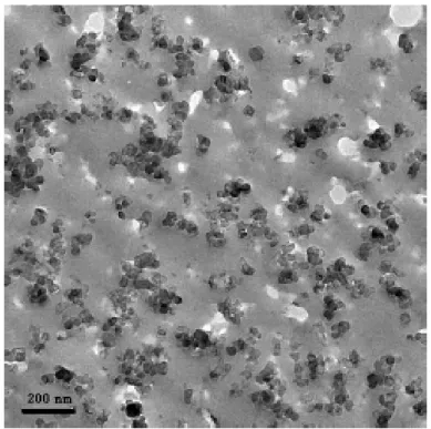
Carbon black (CB) is one of the most common filler used to reinforce elastomers and is made by spherical particles which usually appear as fractal aggregates with average size ranging between 100nm -1mm (Figure 3-5). The reinforcing effect induced on the rubber by the addition of filler is not trivial and depends on several factors including filler composition, shape and dimensions. General conditions for filler reinforcement is the interaction between the filler particles and the polymer. The wide diffusion of the CB is justified not only by its low price but also by the good physical interactions that it can establish with the matrix. In particular, the surface of CB is made by graphitic layers with some high energy surface defects that are unstable absorption sites capable of strong interactions with unsaturated polymers (C=C). The phenomenon is referred as bound rubber and consist in a mobility reduction of rubber bounded on CB particle surfaces that in turn increases the reinforcing effect5,6.
3-21
Figure 3-5 TEM images of CB aggregate in rubber. Re printed from7
3.3.1 Reinforcing effect on linear modulus
The most simple model, aiming to understand the increase on the modulus by the filler addition, is the Einstein-Smallwood 8 equation. Einstein equation was not originally meant for
rubber but to model the effect of filler on the viscosity of dilute solution and Smallwood adapted his equation to explain the increase of the linear modulus of filled rubber using the concept of hydrodynamic effect. This derives from the fact that the filler is a rigid phase and unable to be deformed under the applied load. The Einstein-Smallwood equation consider only one filler-parameter that is its volume fraction 𝝓.
𝑬 𝑬𝟎 𝟏 𝟐. 𝟓𝝓 Equation 3-1
Where, E is the modulus of suspension, E0 is the modulus of the incompressible rubber.
Equation 3-1 is valid for an infinitely dilute system and accounts for the individual contribution of the particles to the reinforcement but is not followed by rubber compounds where interaction between filler and matrix cannot be neglected. A modified version by Guth and Gold 9 who
introduced a second-order term accounting for weak interactions.
3-22
Equation 3-2 is still excessively simplistic and must often be corrected taking in to account other additionally effects including the filler-polymer interactions (in-rubber structure) and elastic properties of the polymer after the vulcanization (polymer network contribution). Generally, the contribution to the modulus is divided in deformation-dependent and deformation-independent as will be discussed in 3.4.1.
3.4 Dissipative mechanisms in filled rubbers
Unfilled rubbers at low strain and far from Tg are mainly elastic and the most significant
viscoelastic contribution is chain friction. Real rubbers anyway, are never used alone and always contain several additives and a certain amount of filler as previously explained. The addition of filler is irremediably related to an increase in viscous dissipation within the rubber system both at small and large strain.
3.4.1 Payne effect
Filled rubbers present a significant drop of the dynamic shear modulus under strain that is generally accompanied by a maximum in dissipation indicated by the peak in tan . The maximum in tan , generally occurs at some tenths of strain, a value that is likely to be close to the values of macroscopic deformation used in cyclic fatigue in filled elastomers. The reduction of modulus with strain was first studied by Payne 10,11 who interpreted it as the result
of the breakage of physical bonds between filler particles, for example van der Waals or London forces, neglecting the role of the matrix itself. Actually, there are several parameters contributing to the Payne effect as: filler content, surface modification of the fillers and morphological characteristic ( volume fraction, filler shape and aspect ratio) 12. A more recent
insight of Payne effect includes the presence of a glassy layer around the filler particles where polymer has reduced mobility. Such glassy layer forms a percolating structure that is responsible for the strain induced softening 13. Generally, all the effects related to the structure
of the material, that contribute to the strain amplitude dependency, are referred as “filler network” while polymer network, hydrodynamic effect and in-rubber structure are generally indicated as non-strain dependent as schematically shown in Figure 3-6.
3-23
Figure 3-6 Schematic behaviour of the complex shear modulus versus dynamic shear deformation.
3.4.2 Mullins effect
Mullins effect was observed for the first time in filled vulcanised rubber around the beginning of the 190014 and later on, extensively studied by Mullins and co-workers for elastomeric
systems when cyclically strained at high deformation 15. Mullin’s effect involves a remarkable
stress softening between the first and the second cycle (at the same maximum strain) accompanied by a visible hysteresis between the loading and unloading path of the stress-strain curves. During the following cycles, within the same range of applied strain, the remaining hysteresis, is significantly smaller than in the first cycle and the stress-strain response tends to overlaps. When the maximum strain is further increased, the loading curve rapidly recovers the original behaviour of a single monotonic test as represented in Figure 3-7.
3-24
Figure 3-7 Illustration of Mullins effect on a filled SBR. Taken from 16
Historically, the Mullins effect was observed in filled and crystallizing rubber when cyclically strained at high deformation but recently several authors reported the same phenomenon also for different systems such as thermoplastic elastomers 17 , hydrogels 18 and other living
systems19. As reviewed by Diani et al. 20 several physical interpretations have been proposed
to justify this dissipative behaviour but a complete agreement has not emerged yet. Some of them involve: microstructural modification of filler aggregates, bond ruptures or slippage of shorter chains between aggregates and network re-arrangement, chain disentanglements, network re-arrangement. Despite the absence of a unique explanation, Mullin’s effect is generally considered as some form of permanent damage that is a-priori unknown and may cover for several phenomena as structural damage, chains rupture, nanovoids formation etc... Different models vary from each other in the definition of such damage parameter. In a recent paper, Merckel and co-workers 21 proposed an easy methodology to quantify the Mullin’s
contribution that allows comparison between different materials. They worked on styrene-butadiene-styrene rubber (SBR) cyclically strained at different, medium to large, strain levels and introduced two damage parameters: one to account for the reduction in linear modulus with applied strain and the other to account for the change in the onset of strain hardening with strain induced during loading at larger strain. They showed that, for filled elastomers these two parameters have the same dependence on strain and also have very similar values. This led
3-25
them to conclude that in filled elastomers, small and large strain damage are two manifestations of a single phenomenon.
3.4.3 Heat Generation
Energy dissipation is also related to the phenomenon of heat generation and temperature increase. As far as the generated heat has enough time to diffuse through the sample this is not really a problem and only leads to some degree of temperature increase within the sample (or heat build up). In other cases, especially for materials with low thermal conductivity and in cyclic conditions at high strain, the generated heat has not enough time to diffuse away and can cause a significant temperature increase in the whole sample or in localised highly stressed region, that can be detrimental 22–24. The amount of dissipated heat per cycle depends on
several factors such as: filler content, maximum strain amplitude, frequency25. Of great interest
is the case of strained samples containing a crack. The crack in fact, creates a much higher local strain at the crack tip than in the bulk and as a consequence generates non uniform surface temperatures within the sample26,27. Persson and Carbone22 used viscoelastic arguments, to
show that, as long as the crack propagates slowly, the heat produced at the crack tip can diffuse away resulting in only small increases in surface temperature. On the other hand, a moderate crack velocity (>1cm/sec) may lead to a large temperature increase ( 1000𝐾) in poorly conductive materials such as rubbers. In this case, the zone close to the propagating crack may be seriously damaged causing a degradation in mechanical resistance and unstable crack propagation. The first accurate measurement of heat sources and local temperature rise at the crack tip was provided by Martinez et al 27. They used an infrared camera to evaluate the local
heat generation at the crack tip in filled SBR and demonstrated the presence of a small zone close to the crack tip, smaller than the area of influence of the crack, where heat dissipation is remarkably higher than the bulk although the final surface temperature was only few degree higher. Their work highlighted the possibility of a local build-up of temperature only in the region at the crack tip that cannot be predicted only by surface measurements and must be considered to improve constitutive modelling of cyclic crack propagation in filled rubbers. An interesting approach was proposed by Saux et al. 28 . They proposed an interesting
correlation between heat build-up and cyclic fatigue in rubber using thermal measurements to deduce the fraction of dissipated energy related to cyclic induced damage.
3-26
3.5 Strain induced crystallization
Strain induced crystallization consists in alignment and further crystallization of polymer chains under tension. Historically, the phenomenon of SIC was firstly observed in NR and deeply studied by means of X-Ray analysis as reviewed by Huneau 29. In case of NR, SIC
appears above a certain threshold that depends on several factors such as filler content, temperature and strain rate. Despite the fact that SIC is completely reversible, the melting of crystallites is generally observed at lower stretch ratios than that required for their crystallization. The different kinetics between formation and melting of crystallites in loading-unloading has been often considered as a dissipative mechanism explaining the hysteresis loop in stress-strain curves of NR and identified as one of the major mechanisms responsible for high fatigue resistance of NR. Interesting, recent studies 30,31 used calorimetric analysis proving
the absence of any mechanical dissipation over a cycle adducing the ability of NR to store mechanical energy without converting it in to heat as one of the principal cause of high crack propagation resistance of NR. The absence of any significant connection between energy dissipation induced by SIC and high fracture resistance of NR was also confirmed by the results of Demassieux et al 32,33. They carried out a comprehensive X-ray investigation at the
crack tip area of filled NR and identified the local stiffening induced by SIC, and the corresponding reduction in strain intensification as the major mechanism contributing to the remarkable cyclic fatigue resistance of NR .
3.6 Nano-cavitation
Another well-known source of dissipation in filled elastomers is the opening of nanocavities during extension33–35. Despite the phenomenon of cavitation in unfilled rubbers, was firstly
proved by Gent and Lindley in 195836 (using specific sample geometry called “poker chip”
which generates hydrostatic pressure in the bulk on the material) it took years before the observation of nanocavities in rubbers. Firsts observations on volume variation in filled rubbers were provided by Le Cam et al. 35 but only more recently, Zhang et al. proposed an accurate
methodology to quantify the presence of nanocavities in filled elastomers. They used real time X-Ray scattering (and the analysis of SAXS scattering invariant) on two different rubbers: SBR and NR.34,37 In particular, they found nanocavities of 20-40nm at the crack tip of filled SBR
that were absent in unfilled rubber suggesting that nano-cavitation was the main cause of volume variation in filled rubber. Furthermore, the fibrillar structure, detected in the crack area
3-27
both in filled NR and SBR, suggested that nano-cavities could act as precursor of the observed ligaments in filled rubbers26,38,39 .
3.7 Concluding remarks
This chapter introduces the topic of vulcanised rubbers and their main dissipative properties. In particular, two main concepts will be stressed in the Part II: the heat dissipation and the Mullins effect. The first topic will be explored in the Chapter 6 for SBR and related to the local conditions at the crack tip of fatigued samples. The second will be frequently recalled, especially in Chapter 3, to discuss and compare the concept of strain-induced damage during cyclic loading condition between TPU and filled thermoset rubbers.
3-28
3.8 References
1. Hamed GR. Materials and compounds. In: Gent AN, ed. Engineering with Rubber. III. Hanser Publishers, Munich; 2012:11-35.
2. Advanced rubbers. https://www.hexpol.com/rubber/resources/advanced-rubber- compounding/sbr/%0Ahttps://omnexus.specialchem.com/selection-guide/styrene-butadiene-rubber-sbr-guide%0A.
3. Coran AY. Vulcanization. In: The Science and Technology of Rubber (Fourth Edition). ; 2013:337-381.
4. Edwards DC. Polymer-filler interactions in rubber reinforcement. J Mater Sci. 1990;25(10):4175-4185. doi:10.1007/BF00581070
5. Leblanc JL. Rubber–filler interactions and rheological properties in filled compounds.
Prog Polym Sci. 2002;27(4):627-687.
6. EM. D. Bound Rubber and Carbon Black Reinforcement. Rubber Chem Technol. 1986;59(3):512-524.
7. Jean A. Etude d’un élastomère chargé, de la nanostructure au macro-comportement. 2009.
8. Smallwood H. Limiting Law of the Reinforcement of Rubber. J Appl Phys. 1944;15(758).
9. Guth, E. Gold O. Theory of filler reinforcement. Phys Rev E. 1938;53:322. 10. Payne AR. Hysteresis in rubber vulcanizates. J Polym Sci Polym Symp.
1974;48(1):169-196. doi:10.1002/polc.5070480114
11. Payne AR. The dynamic properties of carbon black-loaded natural rubber vulcanizates.
J Appl Polym Sci. 1962;Part I(6):57-63.
12. Bokobza L. The reinforcement of elastomeric networks by fillers. Macromol Mater
Eng. 2004;289(7):607-621. doi:10.1002/mame.200400034
13. Berriot J, Montes H, Lequeux F LD. Gradient of glass transition temperature in filled elastomers. Europhys Lett. 2003;64:50-56.
3-29
14. Bouasse, H.; Carriére Z. Courbes de traction du caoutchouc vulcanisé. nn Fac Sci
Toulouse. 1903;5:257-283.
15. Mullins L. Effect of stretchning in rubber. J Rubber Res. 1948;16:275-282. 16. Merckel Y, Brieu M, Diani J, Caillard J. A Mullins softening criterion for general
loading conditions. J Mech Phys Solids. 2012;60(7):1257-1264. doi:10.1016/j.jmps.2012.04.001
17. Qi HJ, Boyce MC. Stress-strain behavior of thermoplastic polyurethanes. Mech Mater. 2005;37(8):817-839. doi:10.1016/j.mechmat.2004.08.001
18. Webber RE, Creton C, Brown HR, Gong JP. Large strain hysteresis and mullins effect of tough double-network hydrogels. Macromolecules. 2007;40(8):2919-2927.
doi:10.1021/ma062924y
19. Munoz, M.J., Rodrigues, J.F. O et al. An experimental study of the mouse skin behaviour: Damage and inelastic aspects. J Biomech. 2008;41(1):93-99.
20. Diani J, Fayolle B, Gilormini P, Diani J, Fayolle B, Gilormini P. A review on the Mullins effect To cite this version : HAL Id : hal-00773015. 2013:601-612.
21. Merckel Y, Diani J, Brieu M, Gilormini P, Caillard J. Characterization of the mullins effect of carbon-black filled rubbers. Rubber Chem Technol. 2011;84(3):402-414. doi:10.5254/1.3592294
22. Carbone G, Persson BNJ. Crack motion in viscoelastic solids: The role of the flash temperature. Eur Phys J E. 2005;17(3):261-281. doi:10.1140/epje/i2005-10013-y 23. Medalia. Heat Generation in Elastomer Compounds Causes and Effects. Rubber Chem
Technol. 1991.
24. Mars W V., Ellul MD. Fatigue Characterization of a Thermoplastic Elastomer. Rubber
Chem Technol. 2017;90(2):367-380. doi:10.5254/rct.17.83780
25. Gent, A. N., Scott KW. Dynamic Mechanical Properties. In: Gent AN, ed. Engineering
with Rubber. Hanser Publishers, Munich; 1992:89-117.
26. Mzabi S. Caractérisation et analyse des mécanismes de fracture en fatigue des élastomères chargés. 2010:1-310.
3-30
27. Martinez JRS, Toussaint E, Balandraud X, et al. Heat and strain measurements at the crack tip of filled rubber under cyclic loadings using full-field techniques To cite this version : HAL Id : hal-01148252 Heat and strain measurements at the crack tip of filled rubber under cyclic loadings using full-f. 2015.
28. Saux V Le, Marco Y, Calloch S, et al. Fast Evaluation of the Fatigue Lifetime of Elastomers Based on a Heat Build-up Protocol and Micro-tomography Measurements To cite this version : HAL Id : hal-00493227 Fast evaluation of the fatigue lifetime of rubber-like materials based on a heat build-u. 2011.
29. Huneau B. Strain-induced crystallization of natural rubber: a review of x-ray diffraction investigations. Rubber Chem Technol. 2011;83(4):425-452.
30. Samaca Martinez JR, Le Cam JB, Balandraud X, Toussaint E, Caillard J. Filler effects on the thermomechanical response of stretched rubbers. Polym Test. 2013;32(5):835-841. doi:10.1016/j.polymertesting.2013.04.003
31. Le Cam JB. Energy storage due to strain-induced crystallization in natural rubber: The physical origin of the mechanical hysteresis. Polymer (Guildf). 2017;127:166-173. doi:10.1016/j.polymer.2017.08.059
32. Demassieux Q. These De Doctorat structural changes in the process zone of a cyclic fatigue crack in filled natural rubber. 2011.
33. Demassieux Q, Berghezan D, Cantournet S, Proudhon H, Creton C. Temperature and aging dependence of strain-induced crystallization and cavitation in highly crosslinked and filled natural rubber. J Polym Sci Part B Polym Phys. 2019;57(12):780-793. doi:10.1002/polb.24832
34. Zhang, H. ,Scholz, A. , Crevoisier J et al. Nanocavitation in Carbon Black Filled Styrene−butadiene rubber under tension detected by real time small angle X-ray scattering.pdf. 2012.
35. Le Cam JB, Toussaint E. Volume variation in stretched natural rubber: Competition between cavitation and stress-induced crystallization. Macromolecules.
2008;41(20):7579-7583. doi:10.1021/ma801290w
36. Gent, A. N.; Lindley PB. Internal rupture of bonded rubber cylinders in tension.
3-31
37. Zhang H, Scholz AK, Vion-Loisel F, et al. Opening and closing of nanocavities under cyclic loading in a soft nanocomposite probed by real-time small-angle X-ray
scattering. Macromolecules. 2013;46(3):900-913. doi:10.1021/ma302325w 38. Le Cam, J. B. , Huneau B. , Verron E. , Gornet L. Mechanism of Fatigue Crack
Growth in Carbon Black Filled Natural Rubber. Macromolecules. 2004:5011-5017. 39. Le Cam JB, Toussaint E. The mechanism of fatigue crack growth in rubbers under
severe loading: The effect of stress-induced crystallization. Macromolecules. 2010;43(10):4708-4714. doi:10.1021/ma100042n
4-33
4
THERMOPLASTIC
ELASTOMERS
Thermoplastic elastomers (TPE) are a widely diffused class of material and are present nearly everywhere in our daily life: toothbrush handles, mobile covers, sneakers soles are only some example of applications (Figure 4-1).
The reason behind the huge diffusion of TPU can thus be summarized in a single concept: they
allow rubberlike materials, that cannot be melted and reprocessed once moulded, to be produced and re-shaped as a thermoplastic1 (e.g. injection moulding, extrusion).
Rubbers are generally known for their characteristic elastic behaviour including the ability to be deformed several times their initial length, and to recover the original shape once the load is removed. The drawback is that classical rubbers are thermoset, that means that irreversible bonds are introduced between certain number of chains through an irreversible process called vulcanization as explained in Chapter 2. On the other side, thermoplastic elastomers have several properties of rubber such as softness and large strain elasticity but, can be rapidly and reversible shaped as a thermoplastic.
4-34
Figure 4-1 Example of TPE applications
4.1 Historical survey and generic classification
The history of TPE begins in 1930 when Goodrich scientists realised that adding plasticizers to PVC would convert hard PVC into a flexible product (Drobny n.d.; Holden 2000). Classic PVC is made by two different structures: syndiotactic and crystalline and amorphous atactic one. The use of plasticizers reduces the glass transition temperature of the amorphous atactic polymer and leads to a flexible polymer consisting in the combination of a rigid phase (that melts at high temperature) with a softer and amorphous one (above its glass transition temperature in usage condition). Despite the fact that plasticized PVC was still lacking many elastomeric properties, the higher flexibility provided by the coexistence of two different phases raised the interest toward a new class of flexible-thermoplastic polymers and opened the route for further development of soft and flexible thermoplastic elastomers. The second breakthrough in the history of the development of thermoplastic elastomers came in 1937 when Otto Bayer and his co-workers recognised the advantage of using a polyaddition reaction (noted since the middle of 1800) to produce useful plastics 1,2. Bayer and co-workers originally
produced polymer fibres consisting in semi-crystalline polyurethane rich domains (below their Tg,) and an amorphous phase (above its glass transition temperature) made of long polyols.
Basically, using a diisocyanate, a short chain and a long chain glycol they reproduced the two-phase structure of PVC that nowadays we know to be the basis of the elastomeric behaviour of thermoplastic elastomers. This discovery received worldwide attention but, due to the constraints induced by the second World war, it was only in 1950 that the first production of commercial polyurethane based thermoplastic elastomers (TPU) started by the Goodrich
4-35
Company. The last and missing milestone that allowed a fast development and commercialization of thermoplastic elastomers was the emergence of the anionic polymerization in 1950 that opened an easy route for the production of block copolymers by alternating soft and hard blocks 1. A new class of polymers, providing several properties of
vulcanised rubber without any chemical vulcanization that could be shaped using thermoplastic techniques was finally discovered.
4.1.1 Classification of TPE
The development of the chemistry of TPE become suddenly extremely fast and creative. Different chemistries, respecting the basic requirement of the formation of the specific multi-phase structure, were explored to produce different TPEs with specific characteristics in terms of strength, elasticity, wear and oil resistance etc. Nowadays TPE can be classified in two major classes: segmented block copolymer and polymer blends 3 as represented in Figure 4-2.
● Segmented copolymers are characterized by alternating soft elastomers and hard thermoplastic block such as polyamide/elastomeric block copolymers (TPAs), polyether/elastomer block copolymers (TPEs), polyurethane/elastomers block copolymer (TPUs).
● Blends are essentially divided in polyolefin blends (TPOs) and dynamically vulcanized blends (TPV)
4-36
Figure 4-2 Example of classification of TPE.
Among all TPEs, the class of TPUs is one of the most versatile. The easy polyurethane chemistry allows to produce TPUs over a wide range of rigidity, with a modulus between 10 and 10.000 MPa 4. As the majority of TPEs, TPUs do not require any curing operation and can
be processed by a variety of techniques including: injection moulding, extrusion and solvent casting. Common properties of TPUs are: good elastic and flexible behaviour and an excellent resistance to abrasion. Additionally, TPU can be produced with low Young’s moduli (<10 MPa) that makes them a possible sustainable alternative to commercial thermoset elastomers. Therefore, the importance of TPUs in the last years has grown because of their less expensive and faster production processes and the possibility of being recycled5.
4.1.2 Chemistry and production of TPUs
TPUs are the product of polyaddition reactions involving three principal reactants: a difunctional linear diol (hydroxyl terminated polyether or polyester) also called soft segment; an aromatic or aliphatic diisocyanate and a chain extender (short chain diol) forming the hard segment. The typical structure of TPU is shown in Figure 4-3
4-37
Figure 4-3 Schematic structure of TPU. Image from 6
Among the most popular aromatic diisocyanates we find the aromatic 4,4'-methylene bisphenyl diisocyanate (MDI) (Error! Reference source not found.) The structural rigidity of the hard segments generally provides the TPU with a high tensile strength, modulus and thermal stability 7. However the aromatic units are susceptible to ultraviolet attack and stabilizers are
required to avoid excessive degradation and yellowing. A common aliphatic alternative is the 1,6-hexamethylene diisocyanate (HDI). TPU with aliphatic hard segments are generally characterised by higher flexibility and phase separation compared to aromatic one. 7–9. There
are two main procedures to produce TPU: one involves a single step where all reagents are mixed, the second requires the creation of a pre-polymer. Both processes have advantages and drawbacks in terms of timer and control of the final product.
A) Single step procedure: it implies that all reactants are mixed together and reacted in one step. This method is simple, however, the whole heat of reaction is released right away which suddenly increases the temperature of the reaction system considerably and makes it often incompatible with industrial procedures 10. Low molecular weight chain
extenders are often the most reactive elements having the tendency to react with the isocyanate faster and before the high molecular weight polyols.
B) Two steps procedure: the flexible block (either a polyether or polyester) reacts with the hard segment in the first step forming a pre-polymer containing both flexible and rigid block terminating with isocyanate groups. Then, the excess of diisocyanate reacts with the chain extender (usually a short chain diol or diamine) leading to the formation of the final TPU Generally, the single step procedure leads to the formation of more random copolymer while the two steps allows to obtain polymers with higher molecular weight (100.000 g/mol) and lower polydispersity index 11.
4-38
4.2 Morphology of TPU
As previously mentioned, the final structure of a TPU is a copolymer composed by the long macrodiol or soft segment (SS) and the diisocyanate & chain extender composing the hard segment (HS). The HS and SS are chemically incompatible and tend to phase separate. Moreover, HS gather together thanks to the favourable hydrogen bonding (red in Figure 4-4) between carbonyl and amine groups developing aggregation of small domains surrounded by a soft phase. Depending on a combination of chemical composition, molecular weight and steric hindrance, the phase separation can be more or less partial but is generally never complete. Hard domains occupy significant volume 5-30 nm and are stiffer than soft domains acting as nanoscale fillers and physical crosslinks at the same time 12,13.
Figure 4-4 Schematic structure of TPU morphology.
4.3 Thermodynamic of phase separation
The tendency to segregate and forming phase-separated microdomains of HS is mainly driven by the chemical incompatibility between soft and hard segments but, as reported by Van Bogart, 11 the influence of temperature plays a key role in determining phase separation and
usage limit of TPU. In a copolymer in fact, the most important variable controlling the phase separation is the free energy of mixing ∆𝐺: