CREEP AND THERMAL RATCHETING OF SOFT
MATERIALS UNDER COMPRESSION
by
Rahul Palaniappan KANTHABHABHA JEYA
MANUSCRIPT-BASED THESIS PRESENTED TO ÉCOLE DE
TECHNOLOGIE SUPÉRIEURE IN PARTIAL FULFILLMENT FOR THE
DEGREE OF DOCTOR OF PHILOSOPHY
Ph.D.
MONTREAL, OCTOBER 03, 2018
ÉCOLE DE TECHNOLOGIE SUPÉRIEURE UNIVERSITÉ DU QUÉBEC
This Creative Commons license allows readers to download this work and share it with others as long as the author is credited. The content of this work may not be modified in anyway or used commercially.
BOARD OF EXAMINERS
THIS THESIS HAS BEEN EVALUATED BY THE FOLLOWING BOARD OF EXAMINERS
Dr. Abdel-Hakim Bouzid, Thesis Supervisor
Département de génie mécanique at École de technologie supérieure
Dr. Ang Dung Ngô, Member, Board of Examiners
Département de génie mécanique at École de technologie supérieure
Dr. Omar Chaallal, Chair of the jury
Département de génie de la Construction at École de technologie supérieure
Dr. Rachid Boukhili, External Evaluator
Département de génie mécanique at École Polytechnique de Montréal
THIS THESIS WAS PRENSENTED AND DEFENDED
IN THE PRESENCE OF A BOARD OF EXAMINERS AND THE PUBLIC ON SEPTEMBER 27, 2018
ACKNOWLEDGMENTS
This PhD thesis would not be possible without the guidance and expertise of my research director, Dr. Abel-Hakim Bouzid. It has been a pleasure pursing my doctoral thesis under his supervision and I wish to convey my utmost gratitude to him. His knowledge and appetite for research in pressure vessel and piping domain along with his mentorship helped me in attaining my PhD.
With immense pleasure, I wish to express my thanks to my parents, Kanthabhabha and Jeya, for their outstanding support, care, encouragement and guidance throughout my life and specifically during my PhD. A big part of my reason to pursue a PhD belongs to my parents, to whom I am forever indebted. Also, I am thankful for the support of my beloved sister, Sathya and my extended family.
My colleagues, in Static and Dynamic Sealing Laboratory, have been an excellent fellow researchers and friends. I would like to appreciate all the help and advice I received from my friends – Linbo Zhu, Ali Oweimer, Valentin Fort, Zijian Zhao, Ali Vafadar, Amir Hasrak, Mohammad Esouilem and Mehdi Kazeminia.
Finally, my special thanks to all the technicians of the department of Mechanical Engineering at ÉTS with special mentions Serge Plamondon and Michel Drouin. I would extend my appreciation to Eric Marcoux and his colleagues at the machine shop for their collaboration and technical support throughout the course of the experimental work.
FLUAGE ET CUMUL DE DEFORMATION PAR CYCLAGE DE TEMPERATURE DES MATÉRIAUX MOUX
Rahul Palaniappan KANTHABHABHA JEYA
RÉSUMÉ
Une accroissement rapide de l'utilisation des matériaux polymères et PRFV par rapport aux matériaux métalliques conventionnels dans la production de composants de réservoirs sous pression et de tuyauterie est devenue une tendance mondiale. Cependant, les normes de conception de l'ASME ainsi que leurs équivalentes européennes pour les matériaux non métalliques ne sont pas spécifiques aux matériaux et, dans l'ensemble, suivent vaguement les normes des matériaux métalliques. Contrairement aux composants PVP métalliques, les composants polymères sont d'âge récent, ce qui limite les données statistiques disponibles sur ce type de matériaux. Parmi les composants PVP polymères, le polychlorure de vinyle (PVC) et le polyéthylène haute densité (PEHD) en constituent la majorité. L'excellente résistance à la corrosion, la légèreté et la facilité de fabrication font de ces deux matériaux polymères le remplacement idéal aux structures métalliques corrosives et lourdes. L'objectif de cette recherche est de caractériser le fluage à long terme et le rochet thermique des matériaux mous.
L’étude s'articule autour de l'analyse du comportement de rochet thermique des matériaux polymériques PVP sélectionnés, y compris les matériaux de joints à base de PTFE et à base de fibres. Le but principal de cette thèse est de caractériser les matériaux polymériques utilisés dans les assemblages à brides boulonnées. Pour l'étude sur les performances des matériaux sélectionnés à haute température, des expérimentations méticuleuses ont été réalisées à l'aide de bancs d'essais équipés de capteurs de haute précision. Comme la plage de température de fonctionnement des matériaux est très différente de celle des joints considérés, les évaluations thermiques des matériaux de brides et des joints ont été effectuées séparément. Tous les matériaux sélectionnés ont été soumis à différentes charges de compression, différentes températures et étaient dans certains cas pré-exposés au fluage pour évaluer l’interaction avec le phénomène de rochet thermique. Les tests de caractérisation des polymères ont été réalisés avec des échantillons en forme d'anneau. De plus, des essais grandeur nature des brides en PVC et PEHD de classe 150 de NPS 3 ont été effectués pour évaluer la relaxation à court terme et les résultats sont comparés à ceux obtenus avec des modèles numériques utilisant la méthode des éléments finis.
Les résultats ont permis de mieux comprendre la vulnérabilité des polymères et des matériaux mous en général au phénomène de rochet thermique. L'étude sur le comportement des matériaux sélectionnés aux cycles thermiques a mis en évidence l'intensification des dommages par fluage sur les matériaux, dont l'ampleur varie en fonction de chaque matériau. De plus, le rochet thermique modifie d'autres propriétés fondamentales des matériaux des brides et des joints, comme le module de fluage et le coefficient de dilatation thermique.
Mots-clef: Assemblage de bride boulonné, Rochet thermique, PEHD, PVC, PTFE et joints à
CREEP AND THERMAL RATCHETING OF SOFT MATERIALS UNDER COMPRESSION
Rahul Palaniappan KANTHABHABHA JEYA
ABSTRACT
A rapid increase in the utilization of polymer and FRP materials over conventional metallic materials in the production of pressure vessel and piping components has become a global trend. However, factually, the design standards of ASME and its European counterpart for non-metallic materials are not material specific and as a whole vaguely follow the standards of metallic materials. Contrary to metallic PVP components, polymer components are of recent ages and this limits the statistical data available on the materials. Among polymer PVP components, polyvinylchloride (PVC) and high-density polyethylene (HDPE) constitute the majority. The inherent excellent corrosion resistance, lightweight and ease of manufacturing make these two polymer materials the ideal replacement over corrosive and heavy metallic structures. The objective of this research is to characterize the long-term creep and thermal ratcheting of soft materials.
The research revolves around the analysis of thermal ratcheting behavior of the selected PVP polymer materials including PTFE and fiber based gasket materials. The core intent of this thesis is to characterize polymer materials used in bolted flange connections. For the investigation of thermal ratcheting performance of the selected materials, meticulous experimentations were carried out using test rigs equipped with high accuracy sensors. As the operating temperature range of selected flange materials are much different from the considered gaskets, the thermal ratcheting evaluation of flanges and gaskets were performed, separately. All the selected materials were subjected to different compressive loads, various ratcheting temperature and few pre-exposure creep to evaluate the thermal ratcheting phenomenon. The characterization tests of polymers were performed with ring shaped samples. Furthermore, full-scale tests of NPS 3 Class 150 PVC and HDPE flanges were conducted to evaluate the short-term relaxation and the results are compared to the finite element counterpart.
The results provided significant insight on the vulnerability of polymer and soft materials to thermal ratcheting phenomenon. The study on the behavior of selected materials to thermal cycling highlighted the intensification of creep damage on the materials, the magnitude of which varied depending on each material. In addition, thermal ratcheting alters other fundamental properties of flange and gasket materials such as creep modulus and coefficient of thermal expansion.
Keywords: Bolted flange joint, Thermal ratcheting, HDPE, PVC, PTFE and Fiber based
TABLE OF CONTENTS
Page
INTRODUCTION ...1
CHAPTER 1 LITERATURE REVIEW ...11
1.1 Introduction ...11
1.2 Review of publications on HDPE material ...12
1.3 Scientific evaluation of Polyvinyl Chloride ...21
1.4 Gasket literature review ...30
1.5 Research objective ...37
CHAPTER 2 EXPERIMENTAL SET-UP ...39
2.1 Introduction ...39
2.2 Universal Gasket Rig ...39
2.2.1 UGR mechanical system ... 40
2.2.2 UGR thermal system ... 43
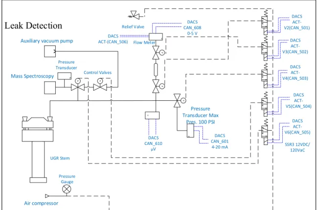
2.2.3 Leak measurement and pressurization system ... 46
2.2.4 LabVIEW data acquisition and control program ... 47
2.2.5 Test procedure ... 48
2.3 HOBT Test Bench...49
2.3.1 Bolt load and displacement measurement... 50
2.3.2 Heat, Pressurization and Leak measurement ... 52
2.3.3 Test Procedure, Applied bolt load and Torque Sequence: ... 52
2.4 Finite Element Modeling ...54
2.4.1 Creep Analysis using ANSYS: ... 56
2.4.2 Modeling and Boundary conditions ... 58
2.4.3 Bolt Pretension ... 59
CHAPTER 3 CREEP AND THERMAL RATCHETING CHARACTERIZATION OF POLYTETRAFLUOROETHYLENE-BASED GASKET MATERIALS ...61
3.1 Abstract ...61
3.2 Introduction ...62
3.3 Experimentation and test procedure ...63
3.4 Results and discussion ...67
3.5 Conclusion ...73
CHAPTER 4 COMPRESSION CREEP AND THERMAL RATCHETING BEHAVIOR OF HIGH DENSITY POLYETHYLENE (HDPE) ...75
4.1 Abstract ...75
4.2 Introduction ...76
4.3 Materials and Methods ...78
4.3.2 Test Procedure and Material Specifications ... 80
4.4 Results and discussion ... 82
4.4.1 Creep Strain ... 82
4.4.2 Creep Modulus ... 85
4.4.3 Thermal Ratcheting ... 87
4.4.3.1 Thermal Ratcheting Strain ... 91
4.5 Conclusion ... 94
CHAPTER 5 EFFECT OF THERMAL RATCHETING ON THE MECHANICAL PROPERTIES OF TEFLON AND FIBER BASED GASKET MATERIALS ... 97
5.1 Abstract ... 97
5.2 Introduction ... 98
5.3 Materials and Methods ... 100
5.3.1 Experimentation: ... 100
5.3.2 Test Procedure and material dimensions: ... 101
5.4 Results and discussions: ... 102
5.4.1 Creep strain ... 102
5.4.2 Creep modulus ... 106
5.4.3 Thermal ratcheting ... 109
5.4.3.1 Percentage of thickness reduction ... 109
5.4.3.2 Coefficient of thermal expansion ... 113
5.5 Conclusion ... 116
CHAPTER 6 INFLUENCE OF THERMAL RATCHETING ON THE CREEP AND MECHANICAL PROPERTIES OF HIGH DENSITY POLYETHYLENE (HDPE) ... 119
6.1 Abstract ... 119
6.2 Introduction ... 120
6.3 Materials and Methods ... 121
6.3.1 Experimental Setup ... 121
6.3.2 Test procedure ... 122
6.4 RESULTS AND DISCUSSIONS ... 124
6.4.1 Creep Strain ... 124
6.4.2 Creep Modulus ... 127
6.4.3 Coefficient of thermal ... 129
6.4.4 Coupled Creep Thermal Ratcheting Analysis ... 132
6.5 Conclusion ... 135
CHAPTER 7 CREEP-RELAXATION MODELING OF HDPE AND PVC BOLTED FLANGE JOINTS ... 137
7.1 Abstract ... 137
7.2 Introduction ... 138
7.3 Experimental Set-up ... 140
7.3.1 Universal Test Rig ... 140
7.3.3 Ring Specimen for Creep Analysis ... 142
7.3.4 Bolted Flange Joint ... 142
7.3.5 Procedure for creep test ... 143
7.3.6 Bolted joint relaxation Test procedure ... 144
7.4 FINITE ELEMENT MODELING ...144
7.4.1 Creep model ... 145
7.4.2 Bolted flange joint model... 145
7.5 Results and Discussion ...146
7.5.1 Experimental Creep Analysis ... 146
7.5.2 Creep Curve Fitting ... 148
7.5.3 Bolt Load Relaxation ... 148
7.6 Conclusion ...155
CONCLUSION AND RECOMMENDATIONS ...157
LIST OF TABLES
Page
Table 2. 1 Material Properties………...………49
Table 2. 2 HDPE bolt load………53
Table 2. 3 PVC Recommended Torque………54
Table 2. 4 Implicit Creep Equations……….57
Table 2. 5 Bolt Pretension Load………...60
Table 3. 1 Gasket dimensions………...64
Table 3. 2 Thermal ratcheting and creep test parameters……….69
Table 4. 1 Creep test parameters………...82
Table 4. 2 Thermal ratcheting test conditions………..….82
Table 5. 1 Gasket dimensions……….102
Table 7. 1 Creep test program……….144
LIST OF FIGURES
Page Figure 0. 1 HDPE piping products……….………...2 Figure 0. 2 HDPE Bolted Flange joint….……….………..3 Figure 0. 3 On-field HDPE flange installation………...3 Figure 1. 1 SEM image of HDPE reinforced with hemp fibre
(Facca et al., 2007)……….……...…..13
Figure 1. 2 Impact of weight of fibers in the tensile strength of
PP/hemp composite (Ku et al., 2011)………...………..13
Figure 1. 3 Morphologies of damaged surface under SEM
(Bhattacharya and Brown, 1985)………...14
Figure 1. 4 SEM picture of HDPE under different test condition
(Lu et al., 1988)………...15
Figure 1. 5 Notch opening at AA (surface), CC (root) and BB (border of craze) against time in ductile region
(Lu and Brown, 1990)……….…16
Figure 1. 6 Fractured surfaces of the specimen at different stresses
(Lu et al., 1991)……….………..17
Figure 1. 7 Microstructure of secondary craze
(Hamouda et al., 2001)………18
Figure 1. 8 Fractured surface of (a) pure tension,
(b) tension-compression and (c) compression fatigue cycles
(Kaiya et al., 1989)……….19
Figure 1. 9 Surface Crack formation (a) no load, (b) mechanical stress, (c) in air - broken TiO2 and (d) in saline solution –
broken TiO2 (Dong et al., 2011)………20 Figure 1. 10 Failure of butt fusion samples (Chen et al., 1997)……….21 Figure 1. 11 Tensile yield strength dependence on volume fraction
of HGB (Liang, 2002)……….………22 Figure 1. 12 SEM image of pine fiber dispersion in PVC resin
(Ge et al., 2004)………..…23 Figure 1. 13 Impact of foam density on the tensile strength
and modulus (Kabir et al., 2006)………..….….24 Figure 1. 14 Comparison experimental and ANSYS results
Figure 1. 15 Effect of ageing in creep strain
(Laiarinandrasana et al., 2011)………..26
Figure 1. 16 Numerical vs experimental results before (left) and after (right) strengthening (Pulngren et al., 2013)………..26
Figure 1. 17 Penetration distance vs Sq. root of time (Mao et al., 2011)………..27
Figure 1. 18 Longitudinal and circumferential property determination from tensile coupon and internal pressurization tests (Wham et al., 2016)………..28
Figure 1. 19 Experimental vs super flange evaluation of creep-relaxation displacement over time (Bouzid and Chaaban, 1997)………..29
Figure 1. 20 Analytical model vs FE model (Nechache and Bouzid, 2008)………...30
Figure 1. 21 CTE vs ratcheting temperature (Bouzid et al., 2001)………...30
Figure 1. 22 Measured vs predicted leak rates (Grine and Bouzid, 2013)…...31
Figure 1. 23 Behavior of ratcheting strain with loading rate (left) and applied mean stress (right) (Chen and Hui, 2005)………....32
Figure 1. 24 Comparison of experimental vs analytical results (Kletschkowski et al., 2002)……….32
Figure 1. 25 Effect of strain rate on DuPont 7A material (Rae and Dattelbaum, 2004)……….33
Figure 1. 26 Experimental vs FEM prediction of uniaxial test data (Bergström and Hilbert, 2005)………..34
Figure 1. 27 Effect of constant axial load (Zhang and Chen, 2009)……….35
Figure 1. 28 Model vs experimental results under different strain rates (Nunes et al., 2011)……….…..36
Figure 1. 29 Influence of applied load on the CTE (Bouzid and Benabdullah, 2015)………..37
Figure 2. 1 Universal Gasket Rig………...40
Figure 2. 2 Schematic of the Mechanical/Hydraulic System……….….41
Figure 2. 3 Axial displacement measurement through LVDT………....42
Figure 2. 4 Full Bridge strain gauge………...43
Figure 2. 5 Electrical ceramic band heater……….….44
Figure 2. 6 (a) external thermocouple (b) internal thermocouple………...45
Figure 2. 8 Schematic diagram of leak detection system………....47
Figure 2. 9 UGR user interface………...48
Figure 2. 10 HOBT Test bench……….…50
Figure 2. 11 HOBT Bolt load measurement……….52
Figure 2. 12 HOBT displacement measurement system………...52
Figure 2. 13 Torque Sequence………..54
Figure 2. 14 Creep stages………..55
Figure 2. 15 (a) HDPE modeling in CATIA, (b) PVC model in ANSYS……….58
Figure 2. 16 Boundary condition in ANSYS………....59
Figure 2. 17 Bolt Pretension……….60
Figure 3. 1 Universal Gasket Rig……….…………...65
Figure 3. 2 Heating system – UGR……….…65
Figure 3. 3 Compressive Creep (a) comparison between expanded and virgin PTFE, (b) Compressive creep response under different loads -virgin PTFE………...68
Figure 3. 4 Thermal ratcheting (a) Expanded PTFE, (b) Virgin PTFE……….70
Figure 3. 5 Percentage of thickness reduction due to ratcheting (a) Expanded PTFE, (b) Virgin PTFE………..71
Figure 3. 6 Coefficient of thermal expansion – Virgin PTFE (a) under applied load, (b) under different ratcheting cycles for 28 MPa, (c) under different ratcheting cycles for 41 MPa……..……….…...…72
Figure 4. 1 Universal gasket rig (a) entire unit, (b) heating system………....79
Figure 4. 2 Specimen sample………...81
Figure 4. 3 Creep strain under different loads at ambient temperature……...84
Figure 4. 4 Creep strain under different temperatures at 14 MPa…………...84
Figure 4. 5 Creep modulus under different loads at ambient temperature………...86
Figure 4. 6 Creep modulus under different temperatures at 14 MPa………...87
Figure 4. 7 Thickness variation of high density polyethylene (HDPE) under 14 MPa of stress and a thermal ratcheting temp. range of 28 to 60°C………...89
Figure 4. 8 Ratcheting of HDPE with and without 1 day creep at 14 MPa of stress………..……...90
Figure 4. 9 Ratcheting of HDPE under 7 and 14 MPa of stress……….…..90
Figure 4. 10 Thermal ratcheting strain under different time periods of initial creep at 14 MPa………...92
Figure 4. 11 Thermal ratcheting strain at different applied loads………..….93
Figure 4. 12 Thermal ratcheting strain under different ratcheting temperature ranges………..……...93
Figure 5. 1 Universal Gasket Rig……….…...101
Figure 5. 2 ePTFE creep strain with and without thermal ratcheting………...104
Figure 5. 3 vPTFE creep strain with and without thermal ratcheting……...105
Figure 5. 4 CNA creep strain with and without thermal ratcheting………....106
Figure 5. 5 ePTFE creep modulus with & without thermal ratcheting………...107
Figure 5. 6 vPTFE creep modulus with and without thermal ratcheting………108
Figure 5. 7 CNA creep modulus with & without thermal ratcheting………..109
Figure 5. 8 ePTFE - % of thickness reduction under the effect ofcreeptimeeriod………...111
Figure 5. 9 vPTFE - % of thickness reduction (a) under different ratcheting temperature range, (b) under the effect of creep time period……….…..112
Figure 5. 10 CNA - % of thickness reduction (a) under different ratcheting temperature range, (b) effect of initial creep exposure prior to ratcheting………..113
Figure 5. 11 ePTFE – Effect of creep pre-exposure on the coefficient of thermal expansion……….114
Figure 5. 12 vPTFE – co-efficient of thermal ratcheting (a) under different ratcheting temperatures, (b) with creep pre-exposure………..115
Figure 5. 13 CNA – co-efficient of thermal ratcheting (a) under different ratcheting temperature range, (b) under the effect of creep time-period………..116
Figure 6. 1 Universal Gasket Rig test bench………...122
Figure 6. 2 HDPE test sample……….123
Figure 6. 3 HDPE creep strain with and without thermal ratcheting………..125
Figure 6. 4 HDPE creep strain projected at same constant temperature after 20 thermal cycles………..126
Figure 6. 6 HDPE - CTE under change in applied compressive load………....130
Figure 6. 7 HDPE - CTE under change in number of thermal cycles………131
Figure 6. 8 HDPE – CTE at different thermal ratcheting temperature………...132
Figure 6. 9 HDPE creep strain at high temperature (45days)……….133
Figure 6. 10 Thickness variation with thermal cycling after 45 days of creep pre-exposure………...134
Figure 6. 11 HDPE - thermal ratcheting strain after 1 and 45 days of pre-exposure creep………...135
Figure 7. 1 Universal Gasket Rig…...……….141
Figure 7. 2 HOBT fixture………...……….141
Figure 7. 3 PVC ring sample……….………..142
Figure 7. 4 HDPE stub flange……….………143
Figure 7. 5 1/8th static model of HDPE (left) and PVC (right)………….………….146
Figure 7. 6 Creep strain under different loads at 60°C (top-left), at 50°C (top-right), at 40°C (bottom-left) and at 23°C (bottom-right)…………..147
Figure 7. 7 Creep Strain under different loads at 60°C (left), at 45°C (right), at 25°C (bottom)………..148
Figure 7. 8 Bolt load relaxation of HDPE flange………...152
Figure 7. 9 Bolt load relaxation of PVC flange………..152
Figure 7. 10 Comparison of bolt load relaxation of HDPE………..153
Figure 7. 11 Comparison of bolt load relaxation of PVC test 1………...154
LIST OF ABREVIATIONS
ASME
CNA
ePTFE
American Society of Mechanical Engineering
Compressed Non-Asbestos
Expanded Polytetrafluoroethylene
FEM
HOBT
Finite Element Method
Hot Blowout Test
LVDT Linear Variable Differential Transformer
PPI
PTFE
Plastic Pipe Institute
Polytetrafluoroethylene
PVP Pressure Vessel and Piping
PVT Pressure Vessel Technology
UGR
vPTFE
Universal Gasket Ring
LIST OF SYMBOLS AND UNITS OF MEASUREMENTS MASS mg Milligram Kg Kilogram ANGL Deg Degree Rad Radian Length/Displacement m Meter mm milimeters µs Micro strain in Inches TEMPERATURE C Centigrade F Fahrenheit TIME S Second H Hours Pressure/Stress
MPa Mega Pascal
GPa Giga Pascal
INTRODUCTION
Modern engineering is striving towards cost effective, environmental friendly and durable products, and the domain of the pressure vessel and piping is no exception. This drive lead to the development of polymeric material components, most notably polyvinylchloride and high-density polyethylene. In little over half a decade from its first commercial production, these two materials have taken total dominance in regards to the polymeric piping industry. The growth of these materials is so humungous that it became an integral part of the urban infrastructure. More than 90% of sewage and domestic water networks in developed countries has been replaced by either of these two plastic materials. The two materials were developed around the same time, in the early 1950’s and had not seen a huge up raise in commercial application until the last three decades. British chemists Eric Fawcett and Reginald Gibson developed the first stable solid form of polyethylene in 1935. In 1953, German scientists Karl Ziegler (belonging to renowned Max Planck Institute) and Erhard Holzkamp invented the High-density polyethylene (HDPE), for which Ziegler won the Noble for chemistry in 1963. The first commercial HDPE pipe was manufactured in 1965.
The high-density polyethylene is a versatile material, the utilization of which ranges from simple plastic bolt to nuclear power plant service water lines. In our Static and Dynamic Sealing Laboratory, the researches are extensive focused on sealing products with particular focus to pressure vessel and piping applications. Hence, this research is narrowed down to understand the behavior of PVC and HDPE materials used in bolted flange joint application.
Figure 0. 1 HDPE piping products
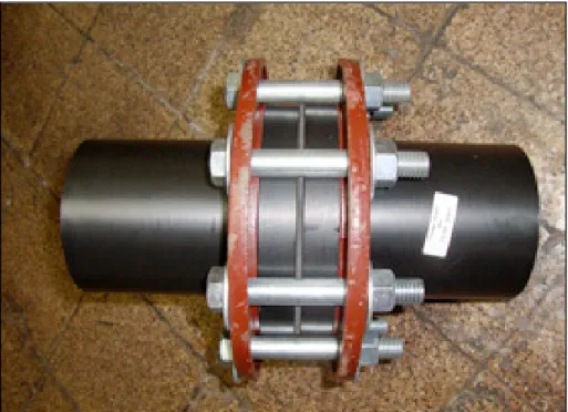
In general, the bolted flanges joints are subjected to compression and so an excellent compressive resistance property is necessary. Bolted flange joint is one of the most commonly used method of connecting pipes and pressure vessel components. In simple terms, the purpose of a bolted flange joint is to provide continuity for the flow of fluid through a piping system. In case of the HDPE, two adjoining stub flanges are held together by applying a compressive force through a pair of metallic rings and a set of bolts and nuts as shown in figure 0.2. Even though there are few alternate methods to connect mating pipe sections together, bolted flanges are the preferred solution because they can facilitate for easy inspection and evaluation of pipes in a large network of connections. Unlike HDPE, PVC flanges can be directly thread and bolted together without any additional metallic rings.
Figure 0. 2 HDPE Bolted Flange joint
Figure 0. 3 On-field HDPE flange installation
Bolted flange joint is one of a key source of leakage failure in the pressure vessel and piping system. All bolted flanges are subjected to a design compressive force to hold the pipe sections together and to avoid any loss of the confined fluid as leakage to the surrounding. Bolted flange joints are the most vulnerable point in any pressurised system and hence one of the most critical link between structures.
Generally, HPDE pipe flanges does not require the use of gasket between their mating surfaces, however, in some special cases soft gasket is used to ensure a tighter seal. The use of soft gasket is a must in metallic and metal to plastic pipe flange connections. Consequently, three commonly used gasket material were tested namely, expanded and virgin polytetrafluoroethylene and compressed non-asbestos fiber gasket. All the test samples, including gasket and flange materials, are commercially available for purchase. The characterisation of flange and gasket materials are performed separately to analysis the behavior of each material under test conditions.
Before discussing the problem with polymeric bolted flanges, some of the most important attributes are briefly presented. The standout of features of the selected polymer materials are durability, ease of manufacturing and fitting, cost effectiveness and non-hazardous. Both HDPE and PVC are well known for their excellent resistance to chemical and corrosion attacks. As a result of their extensive protection property, these pipes are employed in transportation of highly corrosive and slurry fluids. Consequently, a greater service life for piping systems is achieved with same or lower environmental impact than their metallic counterparts. In case of concrete pipes, low pH environments causes shrinkage and chemical attacks on the piping system, which lower their strength. This problem can be overcome with the use of HDPE and PVC pipes.
Another feature of the selected plastic materials is the ease of manufacture, which is very attractive for the PVP industry especially for making pipes and piping components. The preferred laying lengths for conventional metallic pipes are 6 or 12 meters, limiting the production to manufacture hollow cylinders of short lengths. This causes an increase in transportation cost, in number of pipe fitting on field, in human labour with increased risk of handling errors. Due to the advancement in modern manufacturing techniques, HDPE and PVC pipes of small diameters are produced in rolls of 50 m or more and therefore, they are called flexible pipes. The feasibility in production of a single pipe for longer lengths provides for easy field installation and limits the possibility of leakage failure.
Cost effectiveness is one of the key players in modern industrialization. Most industries are keen on expanding the difference between profit and operational cost margins. The mentioned plastic materials provide for exceptional corrosion protection, thereby reducing the cost of maintenance. Less maintenance means increased product life, which directly decreases the replacement cost. In addition, these plastic pipes are relatively light weighted, which can be manufactured in greater lengths. This particular feature helps in easier ground installation and reduces the number of labours need for the installation. Overall, as a consequence of low maintenance, higher product life and easier installations, these flexible pipes are highly cost effective.
Nowadays, health and environmental impact are of major concern and hence many restrictions, in accordance to various international government and regulatory authorities, are imposed in the selection of materials for use in PVP domain. Primarily, both HDPE and PVC are non-toxic materials, which makes them ideal for domestic water transportation. In addition, both of these materials meet the required international standards for operational safety. Furthermore, these two polymers are best for high sensitive environment as they limit requirements for multiple joint connections thereby decreasing the chances of leakage failure.
Problem Statement
As mentioned earlier, this thesis deals with the characterisation of soft materials, which includes two types of polymeric flange materials (HDPE and PVC) and three kinds of gasket materials (ePTFE, vPTFE and CNA). Even though, all of these materials are selected because of their use in bolted flange joint application, each material is evaluated separately. The reason behind individual analysis of these flange and gasket materials is to show the importance of the thermal ratcheting of each material under specific test conditions for extrapolation to other applications.
A bolted flange joint is one of the many methods of connection between two pipes or between a pipe and a vessel. In pressurised systems, this type of joint is critical, as relaxation
due to creep and thermal ratcheting could lead to leakage failure, which can be fatal and hazardous.
Creep is defined as the deformation caused under constant load over a time-period. This phenomenon is extremely common in bolted flanges and it is highly unpreventable. The severity of creep damage is directly proportional to the material temperature. Since this is a time dependent property, it is mandatory to comprehend the creep behavior of the materials, particularly in case of PVP applications. The difference in tensile and compressive creep behaviour is distinct, which is typical of polymeric materials. In addition, the creep resistance of HDPE and PVC are highly important because of their limits in operational temperatures, which are rather low. Gaskets are no exception to creep and in particular Teflon-based PTFE materials. In metallic bolted flange joints, gaskets are established as the primary contributor to creep-relaxation causing loss of bolt tightness and resulting in leakage failure. Although, qualitative and quantitative studies on creep resistance under the influence of tension, compression and temperature of various polymer materials has already been partially treated by fellow researches, none have scrutinised the combined interaction of creep and thermal ratcheting phenomenon.
Thermal ratcheting is defined as the cumulative deformation induced in the material as a result of cycling of temperature. The thermal ratcheting phenomenon is different from mechanical ratcheting where the cumulative damage is caused by load cycling. Thermal ratcheting is usually overlooked in PVP applications because conventional metallic materials have higher temperature resistance. However, this is not the case for polymers and specifically HDPE and PVC, which have low operational temperature limits. As specified previously, the characterisation of flange and gasket materials are performed, separately. This facilitates identification of the test conditions of each material and establish the vulnerability of each material.
Finally, the objective of this PhD thesis is the creep-thermal ratcheting characterisation of polymeric and fiber materials utilized in bolted flange joint application.
Methodology
The characterization of creep, thermal ratcheting and combined creep-thermal ratcheting behavior of all five selected materials were performed using Universal Gasket Rig. For this purpose, extensive experimental tests were carried out in order to obtain quantitative data on the behavior of each material under different imposed test conditions. Schedule 80 HDPE and PVC pipes were precisely cut into ring shaped samples with identical thicknesses by using CMC machine. The research was keenly focused on the compressive creep analysis, which is the primary contributor for bolt load relaxation and consequently initiating failure by leakage.
A combined experimental and numerical approach is employed to analysis the long-term creep behavior of the two flange materials. Since performing a yearlong creep test to grasp the perennial behavior of the material is tiresome and unproductive way of analyzing, a short-term creep evaluation up to several days after the creep transcend to secondary stage is performed at optimal load and temperature conditions. These results provide for defining the creep model, which is required to run numerical simulation and study the relaxation behavior of HDPE and PVC bolted flange joints.
Additionally, experimental investigation on consequence of thermal ratcheting on creep, creep modulus, co-efficient of thermal expansion, percentage of thickness reduction and thermal ratcheting strain were conducted. This approach was adapted mainly due to the fact that the results on the thermal cycling phenomenon is bare minimum and experimental study is the ideal starting point.
To evaluate the numerical simulation results, four full-scale flange creep tests on NPS 3 Class 150 HDPE and PVC materials flanges were conducted. A comparison of experimental and numerical analysis was done and these results acts as the measure of accuracy of the adapted creep model.
Thesis Overview
The contents of this PhD thesis is segregated into seven chapters and a conclusion. The research data are presented in constructive manner for ease of understanding of the reader. The thesis is presented in the “thesis by paper” style of writing.
The first chapter is dedicated to the literature review, which is one of the source of instigation of this research objective. An extensive and qualitative review of existing scientific articles were performed to develop a fundamental and effective problem statement. The literature review helped in understanding the current trend and the state of art conditions of research in PVP domain.
Chapter two elaborates the operational mechanisms of the test rigs and test procedure involved in this characterization research. Since experimentation is the essence of this research, a detailed explanation on the intrigue mechanisms of the machines facilitating the complex creep-thermal ratcheting analysis with highest accuracy is vital.
Third chapter presents the first published journal article on the thermal ratcheting behavior of Teflon based PTFE gaskets. The results of this paper concentrates on the response of expanded and virgin PTFE gaskets to thermal ratcheting phenomenon. The influence of thermal cycling on the percentage of thickness reduction and co-efficient of thermal expansion are also presented.
Fourth chapter revolves around the characterization of high-density polyethylene material subjected to creep and thermal ratcheting. The paper is published in Polymers MDPI journal. This article details the fundamental behavior of HDPE under thermal ratcheting, as no scientific article was ever published in elaborating this phenomenon of the material.
The subsequent chapters five and six present the papers on the combined creep-thermal ratcheting interaction for three types of gasket and HDPE materials, respectively. Both
papers are under review in their respective journals. The amplification of creep damage due to thermal ratcheting is thoroughly presented in them.
Chapter seven compares the numerical and experimental approach on creep-relaxation of HDPE and PVC bolted flange joints. The article describes the effectiveness of experimental test results in constructing the creep models, which are in turn used for predicting creep over a longer period. A full-scale bolted flange tests were conducted to validate the numerical results.
Finally, a broad conclusion highlighting the best of results and elaborating the necessity for improved or updated plastic bolted flange design standard is presented.
CHAPTER 1 LITERATURE REVIEW
1.1 Introduction
This chapter is dedicated to consolidate the existing research work on five selected materials and to explain how the current trend of research assisted in optimizing the objectives of this PhD thesis. Literature review is essential for any type of research, which acts as a pool of information that can assist in developing and understanding a problem statement. In the context of this research work, the literature review helped from narrowing down the research goals to characterising the test conditions for each selected materials. In the modern digital era, the quest for the search of published scientific information has been made easy, which helps in moulding the thesis goals.
A substantial amount of research has been carried out on understanding the mechanical behavior of HDPE, PVC, ePTFE, vPTFE and CNA materials. The research have predominantly focused on the tensile, fatigue, flexure strength and manufacturing techniques as these properties are of high importance in designing structures subjected to different operational conditions. For the sake of simpler writing, the article title, journal name and details are mentioned in the reference section only. In the main text, the first and second author name with their corresponding year of publication is used for one or two authors, and only the first author is used in case of multiple authors.
From a proper scrutinizing of scientific articles, the thesis objective went down from a broader typifying of polymer bolted flange materials to thermal ratcheting characterisation of HPDE, PVC and Teflon materials. Since the latter is primarily used in gasket application, a fiber-based material was considered to have comparative evaluation. An in-depth review of research articles and the desire to focus on the applications related to bolted joints that uses these materials facilitated the decision to characterise their cited properties under
compression. Since all five materials are distinct from each other, a devoted assessment of the prevailing research publications is necessary and hence the following sub-sections briefly detail the state of the art research data published for the chosen materials.
1.2 Review of publications on HDPE material
This subsection gives some short and precise information on the list of publications that are focusing on the characterisation of the high-density polyethylene material. As mentioned in the introduction chapter, the research on HDPE material is more than half century old and the characterisation research has varied from general material characterisation to application specific characterisation. Since the review was done on a large volume of articles, only the most appropriate research findings of the scientific articles were concisely provided in the following paragraphs. The research publications on tensile, compressive and flexure strength, creep, HDPE composite, slow crack growth and mechanical properties of recycled HDPE polymers are presented.
The present day researchers focus on the tensile property of different HDPE composite materials, where the thermoplastic HDPE is added with a fiber material to develop a new composite material. Facca et al. (2007) investigated the tensile property of short natural fibre reinforced thermoplastics (NFRT). The research keenly studied the interaction between HDPE thermoplastic and the natural fibre under tensile loading and characterised the load sharing between the two. The scanning electron microscopic image of HDPE/hemp composite is shown in Figure 1.1.
Figure 1. 1 SEM image of HDPE reinforced with hemp fibre (Facca et al., 2007)
A detailed review on the traction behavior of polymer composites reinforced with natural fibers was done by Ku et al. (2011). The results highlighted that the tensile strength of different HDPE composites found from experimentation and rule of mixture are close to each other. Also, for HDPE composites containing different types of natural fibers, the Halpin-Tsai equation is the most effective method to predict the Young’s modulus of composite materials. The authors show how the tensile strength (Figure1.2) of a composite varies with the percentage by weight of fibers in the mixture.
Figure 1. 2 Impact of weight of fibers in the tensile strength of PP/hemp composite (Ku et al., 2011)
A review of kenaf reinforced polymer composites was carried out by Saba et al. (2015). The research focuses on the evaluation of mechanical property of different polymer materials reinforced by kenaf fibers. Among the various composites combinations reviewed, the article emphasised on 1:1 ratio of kenaf and HPDE resin, which did not show considerable improvement in flexure and tensile properties. Moreover, this composite material demonstrated a reduction in the tensile property at low temperature and an increase when subjected to high temperature.
Bhattacharya and Brown (1985) measured the microstructural changes that initiates slow crack growth in linear polyethylene material. The results show that an instantaneous deformation zone is formed, which grows with constant speed until the beginning of fracture. The researchers discovered that the initial velocity of deformation zone has an activation energy of 100KJ mol-1, which depends on the stress applied. The fibril thinning is the process
that controls crack initiation and growth. Some of the SEM images of the damage polyethylene material is presented in Figure 1.3
Figure 1. 3 Morphologies of damaged surface under SEM (Bhattacharya and Brown, 1985)
It has been found that the crack initiation rate of polyethylene material increases with a decrease of material density. Lu and Brown (1987) did a study on the effect of thermal
history on slow crack growth of linear polyethylene. It was found that the rate of slow crack growth is affected by the variation of the yield point of the material under study.
Brown and Wang (1988) developed a new technique to measure the strain field near the boundary of craze. Based on this method, they established that the strain distribution near the crazes of homopolymers is weaker than the strain distribution in copolymers. Also, they found a way to interpret the stress field associated with the strain field based on the stress-strain curve of the tested polymers.
The researchers of the University of Pennsylvania (Lu et al. 1988) compared the rate of crack growth of HDPE and copolymer. The results from this publication shows a reduction in the rate of SCG of copolymer in comparison to the SCG rate of HDPE. The rate of slow crack growth of copolymer was about 100 to1000 slower than HDPE. The butyl branches of the copolymer was identified as the possible cause of the reduction in the rate of disentanglement and thereby slowing the SCG rate. The authors analysed the microstructural variation during SCG by using a SEM (Figure 1.4).
Figure 1. 4 SEM picture of HDPE under different test condition (Lu et al., 1988)
The failure of a single notched copolymer specimen under a constant tensile load was investigated by Lu and Brown (1990). It was observed that the material experienced three-failure mode: ductile, brittle and transitional. The ultimate mode of three-failure was predicted
from microstructural changes in the notched region. The results showed clearly that the ductile failure was controlled by macroscopic creep behavior while the brittle damage was due to SCG that begins from craze. In addition, the paper elaborated the growth of notch opening over time at surface, root and border of craze during ductile (Figure 1.5), brittle and transitional failure modes.
Figure 1. 5 Notch opening at AA (surface), CC (root) and BB (border of craze) against time
in ductile region (Lu and Brown, 1990)
Another study by Lu et al. (1991), on the discontinuous crack growth under constant load of polyethylene material, measured the kinematics of slow crack growth. It was highlighted that for a temperature decrease, the jump distance decreases as the applied stress increases. The rate of disentanglement of fibrils at the craze dictates the initiation time of fracture. The kinematics of SCG depends on the rate of disentanglement, fibre strength, stress intensity and yield point of the resin. The material clearly exhibits different magnitude of fracture damage under different applied stress (Figure 1.6).
Figure 1. 6 Fractured surfaces of the specimen at different stresses (Lu et al., 1991)
Findley and Tracy (1974) examined the creep behavior of polyethylene and PVC materials under few different tensile stress, temperature and humidity. The creep tests were performed roughly for 132,000 hrs or approximately 16 years. The researchers developed a strain equation, which accurately predicted the creep strain of PVC for the first 2000 hrs. However, the estimated strain of polyethylene was of low accuracy in comparison to the experimental results.
Zhang and Moore (1997) explored the nonlinear behavior of high-density polyethylene samples cut from a thick walled HDPE pipe. The results led to the development of nonlinear viscoelastic (NVE) model and viscoplastic (VP) model by the authors. The predicated values from NVE were not precise for all tested conditions but the results generated from VP model were in good agreement with the experimental results up to the maximum strain reversal value.
The modeling of short and long-term tensile creep of high-density polyethylene was performed by Lai and Bakker (1994). The effect of stress and physical ageing on the creep compliance at an ambient temperature were studied. It was observed that, at larger stress, the
rate of creeping accelerates while at low stress, the effect of ageing was independent of the applied stress and the material exhibits strong nonlinearity. The researchers developed a non-linear creep equation that includes effect of ageing. There is good correlation between the experimental and analytical results.
A study on the creep damage mechanism of polyethylene gas pipes was published by a group of researchers from France (Hamouda et al., 2001). The research concentrated on two types of polyethylene resins, one is a ductile material while the other is brittle material. The slow crack growth clearly controls the lifetime of brittle material. SEM (Figure 1.7) was used in the study of crack initiation and propagation. Even though, catalytic residues act as an initiating factor, this is not true for all extruded resin samples. It was observed that the largest principal stress orients the micro-cracks in a direction perpendicular to it.
Figure 1. 7 Microstructure of secondary craze (Hamouda et al., 2001)
An investigation on the fatigue behavior of high-density polyethylene was conducted under tension-compression, pure tension and pure compression cycles. The researchers (Kaiya et al., 1989) made some morphological observations (Figure 1.8), which revealed that the type
of cyclic deformation dictated the fatigue fracture induced in the material. It was observed that the fracture surface was at 45° with respect to the direction of the applied compressive load under pure compression cycles while it was almost perpendicular to the load condition under tensile fatigue.
Figure 1. 8 Fractured surface of (a) pure tension, (b) tension-compression and (c) compression fatigue cycles (Kaiya et al., 1989)
Dong et al., (2011) experimentally probed into the fatigue behavior HDPE reinforced with silane modified TiO2 composite. The results showed that the composite fatigue life improved
until 30 MPa of the applied stress and at saline bath environment. However, the decline of fatigue life was evident when the applied stress magnitude increased above 30 MPa. By analysing the failure morphologies of the composite, it was understood that silane (Figure 1.9) cannot support the load and it initiates crack in the material surface.
Figure 1. 9 Surface Crack formation (a) no load, (b) mechanical stress, (c) in air - broken TiO2 and (d) in saline solution – broken TiO2
(Dong et al., 2011)
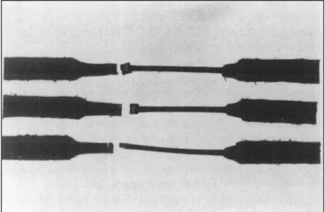
Chen et al., (1997), evaluated the effect of joining mechanism on the bending fatigue and fracture behavior of high-density polyethylene. The study compared three types of joining methods namely butt fusion, electrofusion and plain part. It was found that the butt fusion (Figure 1.10) specimen failed at the fusion zone while the electrofusion specimen failed at fusion joint. The butt fusion joint had a superior resistance to fatigue bending than electrofusion sample; however, the plain unwelded sample exhibited the highest resistance.
Figure 1. 10 Failure of butt fusion samples (Chen et al., 1997) 1.3 Scientific evaluation of Polyvinyl Chloride
Polyvinyl chloride or PVC, as commonly known, is the most valuable and the largest used polymeric material of all time. The utility of PVC is extraordinary, which ranges from electric cables to pipes, from clothing to healthcare, from furniture to construction etc… It has been more than a century since the first commercial production of PVC by Fritz Klatte. Since then the growth of PVC is undoubtedly significant. With growth and popularity comes the assessment and evaluation, which has led to characterisation of the material in general and to specific application. Since 1912, a humungous amount of research were conducted on characterising PVC. Reviewing and summarizing all the scientific articles would be impossible and tedious; therefore, this section of the chapter will broadly discuss the recent publications in the characterisation of PVC material.
In the last three decades, the tensile, compression and flexure characterisation researches are mainly fixated on PVC thermoplastic composites. The study on characterising the impact and tensile strength of PVC composite filled with hollow glass beads by Liang 2002 demonstrated that the tensile yield strength (Figure 1.11) of the composite decreased with increase in volume fraction of the hollow glass bead (HGB). However, the tensile break
strength increases a little with increase of HGB. The impact strength decreased significantly with the increase of fiber volume fraction but when the fiber volume fraction is higher than 5% of the total, then the rate of decrease of the impact strength is not significant.
Figure 1. 11 Tensile yield strength dependence on volume fraction of HGB (Liang, 2002)
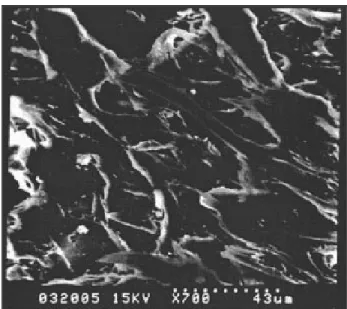
Ge et al., (2004) performed a comparative study on the tensile and thermal properties of two PVC composites reinforced with bamboo and pine flour, respectively. It was observed that the PVC composite with pine flour showed better tensile strength then the other composite under the same loading and particle size conditions. In comparison to bamboo fibers, short pine fiber inside PVC resin showed greater alignment and dispersion under scanning microscope evaluation (Figure 1.12).
Figure 1. 12 SEM image of pine fiber dispersion in PVC resin (Ge et al., 2004)
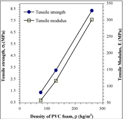
The tensile strength and fracture toughness of PVC foam material was examined. The authors (Kabir et al., 2006) found that the level of cross-linking bonds dominates the fracture toughness of the material; however, the cracks in rise and flow direction and loading rate does not produce a noteworthy effect on fracture toughness. Experimental tests revealed that the foam density (Figure 1.13) dictates the tensile strength, modulus and fracture toughness of the material. It was observed that all foam samples failed in a brittle manner.
Figure 1. 13 Impact of foam density on the tensile strength and modulus (Kabir et al., 2006)
The work by Sabuncuoglu et al., (2011) examined the viscoelastic properties of polypropylene material using a series of creep tests. They limited the creep tests to very short time in order to limit the sudden drop of stress during the initial few seconds. The results were verified with the viscoelastic model was in good concordance with experimental tests, where the samples were subjected to tensile strain rates lower than 0.01s-1.
The primary creep behavior of polypropylene was studied experimentally and numerically to simulate long-term behavior of the material (Dropik et al., 2002). These researchers performed experimental creep tests and utilized a procedure developed by Dougherty, 1996 to determine the creep constants for non-linear Maxwell model. The established constants were used in ANSYS creep formulas and the creep behavior of the material was simulated. On comparing experimental results with ANSYS results, there was a 11.1% and a 16.6% difference for creep and relaxation (Figure 1.14), respectively.
Figure 1. 14 Comparison experimental and ANSYS results for relaxation (Dropik et al., 2002)
Barbero and Ford (2004) modeled the effect of physical ageing and temperature on the creep and relaxation behavior of polymers. The developed equivalent time temperature model (ETT) is an extension of the existing equivalent time method. The time-temperature superposition method used in the article is applicable only to unaged data. The procedure to shift creep data to time-temperature superposition master curve was detailed.
Laiarinandrasana et al., (2011) investigated the creep behavior of PVC on round bar samples. For experimentation, the researchers utilized virgin and aged pipes (22 to 35 years of service). Fracture mechanics for the creep of solid tools were used to study the creep failure of PVC pipes under internal pressure. From the experimental data, it was found that the creep strain rate was higher at the external surface than at the internal surface of smooth PVC pipes. The effect of ageing (Figure1.15) was cited as the reason for this decrease in creep strain.
Figure 1. 15 Effect of ageing in creep strain (Laiarinandrasana et al., 2011)
A group of engineers (Pulngern et al., 2013) worked on finite element simulation of strengthened wood/PVC composite to predict the creep response of the material. The research detailed the effect of strengthening high carbon steel bars on the performance of the composite. The power creep law was used to determine the constants and the results from the ABAQUS software showed a good correlation (Figure 1.16) with the experimental data.
Figure 1. 16 Numerical vs experimental results before (left) and after (right) strengthening (Pulngren et al., 2013)
An experimental study on the bending fatigue of PVC pipe and joints was performed by two professors from university of Akron (Scavuzzo and Srivatsan, 2006). The PVC samples were subjected to an internal pressure (varying from 0 to 280 psig) and a four point bending to evaluate its response to bending fatigue. It was deduced that the internal pressure acting on
the pipe plays a significant role in determine the fatigue life of the PVC pipe. The samples tested under four point bending without internal pressure were found to have weaker fatigue life than the samples tested with internal pressure. It was suggested that the fatigue cycling rate and the hold times at maximum load might affect the fatigue strength of the PVC pipe.
The permeation of organic solvents into the PVC pipe was extensively studied by Mao et al., (2011). The researchers found that the external chemical activity controls the propagation rate, where the rate of propagation increases with the increase in number of organic solvents in the medium of transfer. It was also determined that the permeability of contaminants depends on the time of contact between the pipe and fluid (Figure 1.17). After two years of test, it was observed that PVC pipe showed highest resistance to permeation commercial gasoline among other tested fluids.
Figure 1. 17 Penetration distance vs Sq. root of time (Mao et al., 2011)
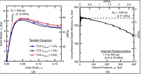
The characterization of oriented polyvinyl chloride (PVCO) to ground scale deformation was studied by a group of civil engineers from Cornell University (Wham et al., 2016). They evaluated the capacity of PVCO pipe with bell and spigot joints to resist large deformations. The assessment varied from full-scale fault rupture test to fundamental material property
evaluations. The axial pullout and compressive load capacity of the joints control the performance of the pipe. The longitudinal and circumferential (Figure 1.18) elastic modulus and Poisson ratios were obtained from an uniaxial tensile coupon test and an internal pressurization test, respectively. The results highlighted that a significant amount of fault movement can be accommodated by PVCO pipeline.
Figure 1. 18 Longitudinal and circumferential property determination from tensile coupon and internal pressurization tests (Wham et al., 2016)
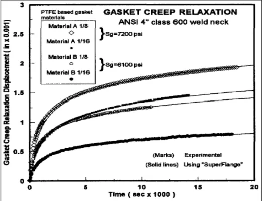
Bouzid and Chaaban (1997) developed a method to measure accurately the relaxation in bolted flange joints. This article details the working of inbuilt computer program called SuperFlange ©, which can predict relaxation of bolted joints and the results act as a realistic evaluation of the leak over time. The proposed model effectively predicted the creep relaxation displacement of different gaskets at different thicknesses, as shown in Figure 1.19.
Figure 1. 19 Experimental vs super flange evaluation of creep-relaxation displacement over time (Bouzid and Chaaban, 1997)
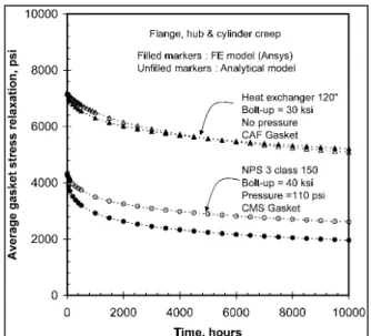
The impact of shell and hub creep in the relaxation analysis of bolted flange joints was assessed by Nechache and Bouzid (2008). The paper highlights that the shell and hub were accountable for 60% loss of bolt load under the evaluated conditions. Also, the article compared the analytical model (Figure 1.20) with the results from the FEM simulation, which were found to be in close agreement with each other.
Figure 1. 20 Analytical model vs FE model (Nechache and Bouzid, 2008)
1.4 Gasket literature review
The service temperature assessment of PTFE based gasket by Bouzid et al. (2001) provided new insights to the HOBT characterisation of PTFE gaskets. The paper emphasised the effect of thermal cycling on the creep-relaxation behavior of gasket materials. The authors looked into the effect of cumulative damage and discussed several methods to determine the coefficient of thermal expansion (Figure 1.21) of gasket materials.
Figure 1. 21 CTE vs ratcheting temperature (Bouzid et al., 2001)
Grine and Bouzid (2013) examined the leak rates through porous gaskets at high temperature. The authors utilized the analytical model of slip flow regime (Grine and Bouzid, 2011) to validate the model with experimental data. The obtained results showed the effectiveness of the developed model (Figure 1.22).
Figure 1. 22 Measured vs predicted leak rates (Grine and Bouzid, 2013)
The compressive ratcheting behavior and the effect of loading rate on the stress-strain response of PTFE material were probed by Chen and Hui (2005). It was observed that the material was sensitive to the loading rate up to 40 N/s after which the loading rate (Figure 1.23) becomes insignificant to ratcheting strain induced in the material. The magnitude of ratcheting strain was the highest at the lowest tested loading rate; however, the ratcheting strain increased with an increase in the mean stress applied to the test samples.
Figure 1. 23 Behavior of ratcheting strain with loading rate (left) and applied mean stress (right) (Chen and Hui, 2005)
Kletschkowski et al., (2002) developed a model to predict the nonlinear behavior of polytetrafluoroethylene material. The developed model predicted the short and long-term behavior (Figure 1.24) of filled PTFE accurately. The model works well under small and finite strains.
Figure 1. 24 Comparison of experimental vs analytical results (Kletschkowski et al., 2002)
The compression property of Teflon based PTFE materials samples from DuPont, 7A and 7C, were experimental studied (Rae and Dattelbaum, 2004). The research probed into the
effect of strain rates and temperature on the mechanical properties of the materials. The strain rate and temperature varied from 10-4 to 10-1 s-1 and from -198 to 200°C, respectively. The
two material variants demonstrated similar true strain relaxation upon unloading (Figure 1.25) under different loading and unloading strain rates. The impact of temperature was also evident. Lowering of temperature causes an increase in true stress under the same loading rate.
Figure 1. 25 Effect of strain rate on DuPont 7A material (Rae and Dattelbaum, 2004)
Bergström and Hilbert (2005) worked on establishing a constitutive model to predict temperature and time dependent mechanical properties of fluoropolymers. The researchers conducted a variety of experimental tests to validate the capabilities of this new model. The results demonstrated the accuracy of the constitutive model in predicting the material response. Figure 1.26 shows the effectiveness of the model in predicting the uniaxial tension and compression behavior of glass filled PTFE samples. In addition, the model can predict cyclic uniaxial loading.
Figure 1. 26 Experimental vs FEM prediction of uniaxial test data (Bergström and Hilbert, 2005)
Solid cylindrical polytetrafluoroethylene specimens were subjected to experimental mechanical ratcheting tests (Zhang and Chen, 2009). The results demonstrated that the ratcheting strain was influenced by the applied axial stress (Figure 1.27), cyclic shear strain range and shear strain rate. While both axial stress and shear strain range proportionally influenced the ratcheting strain, the decrease in shear strain rate amplified the ratcheting strain. The impact of loading history on the progress of ratcheting strains was evident and this effect was due to the hardening effect under previous loading.
Figure 1. 27 Effect of constant axial load (Zhang and Chen, 2009)
The paper by Nunes et al., (2011) focused on developing a new model to predict the mechanical behavior of polytetrafluoroethylene material under tensile loading with different strain rates. Visual strain measurements using a non-contact video extensometer were taken in this experimental evaluation. The values of constants used in the developed model were determined from experimental test results obtained under different constant strain rates. On comparing the experimental data with the analytical results, a good agreement is observed as seen in Figure 1.28.
Figure 1. 28 Model vs experimental results under different strain rates (Nunes et al., 2011)
Existing standards (ASTM E 228-1, E 831-14, D 696-16) were reviewed to adopt a test procedure to measure linear thermal expansion coefficient of the tested materials. In addition, the ASTM standard for Hot blowout test for gasket material was studied. Significant amount knowledge was obtained by studying the research publications on the thermal characterisation and creep resistance of Teflon based PTFE gasket material (Marchand et al. 1992, Derenne et al. 1999, Payne and Bazergui 1990, Payne et al. 1987).
Bouzid and Benabdullah (2015) worked on analysing the HOBT test procedure and suggested to increase the number thermal cycling for improvement of the test standard. The authors performed up to twenty thermal cycles and looked into the effect of thermal cycles on bolt load relaxation of bolted flange joint. Furthermore, the researchers showed the influence of applied stress on the coefficient of thermal expansion (Figure 1.29) of PTFE material.
Figure 1. 29 Influence of applied load on the CTE (Bouzid and Benabdullah, 2015)
1.5 Research objective
From the extensive study and review of scientific articles and from an analysis of the current trend of research on characterisation of soft materials, it is clear that the amount of research on thermal ratcheting behavior of the selected materials is rare and the information on the adverse effect of this phenomenon is very limited. Furthermore, there is no published research of the interaction of thermal ratcheting and the creep response of these chosen materials.
The current state of the art in the characterisation researches focus on improving the properties of HDPE and PVC materials by developing a new composite material out thermoplastic resins; thereby widening the application range of these flexible plastic materials. However, the application of HDPE and PVC in pressure vessel and piping domain is out pacing the volume of application-oriented research done on these materials. As explained earlier, bolted flange connection is one of the most critical component of the PVP system. With the ever-increasing operational and fugitive emission restrictions, it is important to characterise the behavior of HDPE and PVC bolted flange joints. The current ASME and European polymeric bolted flange joint standards are directly derived from
standards of metallic bolted flange joint. However, not only the thermal and creep properties of polymers and soft materials are significantly different from those of its metallic counterparts, their high temperature data under compressive load is simply not available. Because of these factors, the research is focused to follow the objectives or goals described below:
o Study thermal ratcheting phenomena of few Teflon and fiber based gasket materials o Study the cumulative damage of HDPE and PVC materials produced by thermal
ratcheting under compressive load
o Investigate the vulnerability of gasket materials to creep and thermal ratcheting o Study the relationship between thermal ratcheting on the creep behavior of HDPE and
PVC materials
o Conduct an analytical and numerical modeling of load relaxation of HDPE and PVC bolted flange joints subjected to short-term creep.
CHAPTER 2
EXPERIMENTAL SET-UP
2.1 Introduction
This chapter provides a detailed description of the working principal of Universal Gasket Rig and Hot Blowout Test bench. The sophistication of these two home-built test equipment paved the way for successful testing and characterisation of the selected test materials. Both test rigs were designed and built by students of the Static and Dynamic Sealing Laboratory with the assistance of department technicians. The primary purpose of the HOBT rig is to perform hot blowout tests on PTFE-based gaskets to determine their safe operating temperature limits and the UGR was designed to characterise gasket materials for leak and relaxation performances. Both test equipment were modified over time to accommodate for the analysis of different types of gasket and flange materials, fluid media and operating conditions.
The intricacy of the UGR and HOBT are presented in the following sections of this chapter. In the framework of this research, the creep and thermal ratcheting characterisation of the selected materials are achieved through the use of universal gasket rig and the full scale relaxation tests of HDPE and PVC bolted flange joints are conducted using the HOBT rig.
2.2 Universal Gasket Rig
The speciality of the universal gasket rig (Figure 2.1) is its capability to execute compressive creep, relaxation, leak and high temperature analysis of any material as along it satisfies the dimensional constraints of the machine. Since the initial intention of UGR is to investigate the behavior of gaskets, the machine was design to facilitate a gasket shaped or in general ring shaped samples. The working principal of the machine can be sub-divided into sections