Science Arts & Métiers (SAM)
is an open access repository that collects the work of Arts et Métiers Institute of
Technology researchers and makes it freely available over the web where possible.
This is an author-deposited version published in:
https://sam.ensam.eu
Handle ID: .
http://hdl.handle.net/10985/8374
To cite this version :
Ruding LOU, Jean-Philippe PERNOT, Alexei MIKCHEVITCH, Philippe VERON - Merging
enriched Finite Element triangle meshes for fast prototyping of alternate solutions in the context of
industrial maintenance - Computer-Aided Design - Vol. 42, p.670-681 - 2010
Any correspondence concerning this service should be sent to the repository
Administrator :
archiveouverte@ensam.eu
Science Arts & Métiers (SAM)
is an open access repository that collects the work of Arts et Métiers ParisTech
researchers and makes it freely available over the web where possible.
This is an author-deposited version published in:
http://sam.ensam.eu
Handle ID: .
http://hdl.handle.net/null
To cite this version :
Ruding LOU, Jean-Philippe PERNOT, Alexei MIKCHEVITCH, Philippe VERON - Merging
enriched Finite Element triangle meshes for fast prototyping of alternate solutions in the context of
industrial maintenance - Computer-Aided Design - Vol. 42, p.670-681 - 2010
Any correspondence concerning this service should be sent to the repository
Administrator :
archiveouverte@ensam.eu
Merging enriched Finite Element triangle meshes for fast prototyping of
alternate solutions in the context of industrial maintenance
Ruding Lou
a, Jean-Philippe Pernot
a,∗, Alexei Mikchevitch
b, Philippe Véron
aaArts et Métiers ParisTech, LSIS – UMR CNRS 6168, 2, cours des Arts et Métiers, 13617 Aix-en-Provence cedex 1, France bResearch and Development Direction, Electricité de France Group, 1, avenue du Général de Gaulle, 92141 Clamart cedex, France
a r t i c l e i n f o
Article history:
Received 20 May 2008 Accepted 15 January 2010
Keywords:
Finite Element modelling Triangle mesh intersection Constrained triangulation Aspect ratio
Mesh deformation Semantics
a b s t r a c t
A new approach to the merging of Finite Element (FE) triangle meshes is proposed. Not only it takes into account the geometric aspects, but it also considers the way the semantic information possibly associated to the groups of entities (nodes, faces) can be maintained. Such high level modification capabilities are of major importance in all the engineering activities requiring fast modifications of meshes without going back to the CAD model. This is especially true in the context of industrial maintenance where the engineers often have to solve critical problems in very short time. Indeed, in this case, the product is already designed, the CAD models are not necessarily available and the FE models might be tuned. Thus, the product behaviour has to be studied and improved during its exploitation while prototyping directly several alternate solutions. Such a framework also finds interest in the preliminary design phases where alternative solutions have to be simulated. The algorithm first removes the intersecting faces in an n-ring neighbourhood so that the filling of the created holes produces triangles whose sizes smoothly evolve according to the possibly heterogeneous sizes of the surrounding triangles. The hole-filling algorithm is driven by an aspect ratio factor which ensures that the produced triangulation fits well the FE requirements. It is also constrained by the boundaries of the groups of entities gathering together the simulation semantic. The filled areas are then deformed to blend smoothly with the surroundings meshes.
© 2010 Elsevier Ltd. All rights reserved.
1. Introduction
Nowadays, the mainstream methodology for product behaviour analysis and conceptual solution assessment relies on the fol-lowing steps: conceptual phase, Computer-Aided Design (CAD) modelling, meshing and simulation model preparation, Finite Ele-ment (FE) simulation, result analysis and optimization loops [1,2]. However, in the context of maintenance and lifecycle problem analysis, the product is already designed, the CAD models are not necessarily available and the product behaviour has to be studied and improved during its exploitation. Companies exploiting com-plex installations are currently subjected to various constraints crucial from a production point of view. They can be relative to the time and cost of the production process stops, to the efficiency of maintenance solutions, to production safety criteria, etc. For example, in the field of power production, it is critical to identify the problem source and to provide the appropriate solution while
∗Corresponding author. Tel.: +33 4 42 93 81 96; fax: +33 4 42 93 81 00. E-mail addresses:ruding.lou@aix.ensam.fr(R. Lou),
jean-philippe.pernot@aix.ensam.fr(J.-P. Pernot),alexei.mikchevitch@edf.fr
(A. Mikchevitch),philippe.veron@aix.ensam.fr(P. Véron).
taking care of the triptych: Time, Quality and Cost. As a reference, for the Electricité de France (EDF) Group, the total cost of one day of stop of a nuclear power station represents several hundreds of thousands of euros.
In this context, it is clear that the optimization of the stop times necessarily goes through the optimization of the time spent for the various numerical simulations (e.g. mechanical resistance assess-ment, vibration analysis, contra-expertise). Sometime, the model preparation step, including the CAD modelling, the development of complex meshes adapted to specific FE simulations, the accurate identification of the unknown parameters, the prototyping and as-sessment of the proposed solution can exceed 50% of the time re-quired for the full operational study.
In this paper, we present a new research direction allowing reducing the time of the studies. The newly developed prototyping method does not necessarily go back to the CAD models and set up a framework for the definition of a CAD-less approach. Actually, the idea is to enable direct modification of complex meshes. This approach enables to avoid multiple and time-consuming iterative updatings of the CAD models, as well as the tedious remeshing of potentially complex shapes. Not only it takes into account the geometric aspects, but it also considers the way the semantic information possibly associated to the groups of FE entities can be
0010-4485/$ – see front matter©2010 Elsevier Ltd. All rights reserved.
maintained during the modifications. These semantic data enrich the FE mesh models with information that are classically relative to the defining materials, boundary conditions and external forces. A new algorithm is proposed and enables the merging of triangle meshes while taking into account the boundaries of FE groups. Thus, many underlying problems are circumvented and the time of study is reduced. The proposed approach is particularly efficient in the case of fast prototyping of local structural modifications.
The paper is organized as follows. First, the specificities in the field of production machinery maintenance are presented on some EDF engineering projects (Section2). The new prototyping framework is also proposed. Section 3 depicts a state-of-the-art of the methods enabling local mesh modifications. Based on this analysis, we introduce our new triangle meshes merging approach together with the associated algorithms (Sections 4
and5). The overall process and algorithms are finally tested on several examples including an example relative to an EDF project (Section6). The last section concludes this paper while coming back on the achieved results and potential future developments.
2. From current industrial practices to our fast prototyping framework
2.1. Industrial study context
The expertise of problems on production sites corresponds to the analysis of the equipments’ normal functioning. Such exper-tises generally concern planned preventative and/or occasional maintenance of machineries, lifecycle assessments or some im-provements of the production equipment behaviours. To avoid the stop of production cells, it is critical to provide quickly the op-timized solution and to ensure its effectiveness while conform-ing to the production safety criteria. In the nuclear field, if local structural modifications are generally allowed, it is not possible to perform global modifications. Moreover, even a small local modi-fication requires product cycle stops and validation expertise done by the safety authorities. Hence, solutions requiring significant modifications inducing long stops of production sites or complete review of a new production cycle are not realized.
2.2. Current industrial practices and underlying problems
The preparation of FE analyses is generally carried out while successively building the CAD models, generating the meshes, preparing the simulation models adapted to the adopted FE analy-sis code. Classically, the evaluation of alternate solutions requires several updates of the initial CAD models [2].
If this workflow is widespread, its use is not well adapted to the maintenance context. Actually, it requires the access to the CAD model construction tree [3] which is not always possible. Further-more, some complex meshes adapted to the advanced FE simula-tion might contain many different entities difficult to model using a CAD approach. They correspond to double mesh entities (e.g. 2D el-ements, nodes), mesh entity groups to define mechanic/geometric parameters as well as to apply specific mechanical relations or boundary conditions (BCs), specific groups to model a complex phenomenon (e.g. crack, contact problems). If the designer has to go back to the CAD model, he/she loses this specific information that will be redefined later on. Sometime, the CAD models are even not available and redesigning them starting from scratch would be too time-consuming.
To illustrate these limits, let us consider the example ofFig. 1
that presents complex models the EDF engineers have to face.
Fig. 1a shows the CAD model of a caisson in which a structural modification has to be performed. According to the traditional prototyping method, this study would include the following steps:
Fig. 1. Local structural modifications of a caisson (a) realized on the CAD model (b) before the remeshing (c) and the redefinition of the semantic data (courtesy EDF R&D).
(1) development of the complex CAD model which does not exist (Fig. 1a);
(2) development of an advanced mesh model taking into account different aspects such as mesh quality criteria, mechanical modelling hypotheses (Fig. 1c);
(3) creation of numerous mesh entity groups on which different FE semantics will be defined in the following step (5). These groups (30 on the example of Fig. 1) can be created either manually one by one, or more automatically while using the partitioning of the initial CAD model. This time-consuming step requires a very good skill;
(4) tuning/validation of the FE model through experimental results;
(5) FE analysis based on the modelling hypotheses and previously defined FE simulation semantics (step 3): description of links between 1D and 3D elements, characterization of the materials and specific geometric/mechanic parameters, definition of BCs and loads;
(6) prototyping of the envisaged solution, i.e. an incision of the stiffener in the present case, through an update of the initial CAD model (Fig. 1b);
(7) going back to the second step in order to evaluate this solution, and so on.
Here, it seems quite clear that going back to the CAD model is not the most appropriate solution. This is especially true when the model contains a huge amount of semantic data. For example, some EDF models can contain up to 500 groups dedicated to the FE analysis as well as particular post-processing. Unfortunately, current commercial CAD systems do not make it possible to automatize the process of enriched mesh modification. Thus, even a small local change necessitates expensive complete updating of the models.
Furthermore, the CAD strategy mainly considers the object outer surfaces as ‘‘perfect’’ in the sense that it idealizes the real structures. This is not adapted to design ‘‘as-built’’ simulation models since all the ‘‘imperfections’’ of the real structures are not captured. Meshes are more adapted since they are tuned to better fit what can be measured ‘‘on site’’.
2.3. A new digital prototyping method
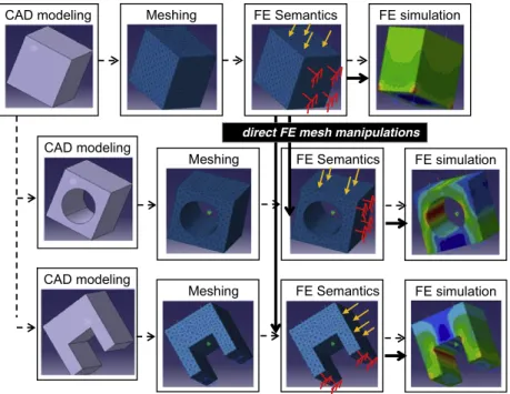
In this paper, we go towards the definition of a CAD-less methodology that works directly at the level of the enriched meshes (Fig. 2). The idea relies on the removing of the hard steps of CAD modification, remeshing and FE complex model preparation in order to bring local modifications directly onto the initial FE mesh
672 R. Lou et al. / Computer-Aided Design 42 (2010) 670–681
direct FE mesh manipulations
Fig. 2. Classical design process (dot lines) versus our design process adapted to the industrial maintenance and preliminary design phases (continuous lines).
while maintaining and potentially transferring the FE semantic data. This process is particularly efficient when prototyping local structural modifications. It also finds interest in the product design preliminary phases where several alternative solutions can be foreseen and simulated.
Using this approach, we somehow introduce a break within the complete digital workflow. If they exist, the CAD models are no longer consistent with the FE models. Anyhow, when the FE meshes become stable after several optimization loops, designers can always update their CAD models, if they exist. In practice, EDF engineers do not spend time to do it since the meshes are much more appropriate to represent the reality measured ‘‘on site’’.
To create a real breakthrough in the way designers can ma-nipulate the meshes, at least all the operators working on CAD models [3] should become available for enriched FE meshes: ma-terial addition, mama-terial deletion and mama-terial incision opera-tors. Each operator has to allow keeping and potentially updating the FE simulation semantic data supported by the mesh groups. Unfortunately, current commercial CAD software do not favour such a direct approach. Some CAD systems such as IDEAS r, LMS
Virtual.Lab r, SALOME r propose limited functions enabling solely
the assembling of particular 2D meshes.
In our prototype software, the geometry and topology of the mesh as well as the groups of FE entities are imported and exported using the.UNV file format of IDEAS r. The semantic information
(e.g. boundary conditions, materials) attached to these groups are stored within the.com file format of Code_ASTER r
[4]. These choices are not restrictive since all the computations are performed using our own data structure and since the proposed algorithms are not built on top of these file formats.
2.4. Merging of enriched triangle meshes
In this paper, we do not pretend to answer all the needs in terms of mesh manipulations. Actually, we have been interested in the definition of a set of models, methods and tools to directly merge two triangle meshes while keeping intact the potentially associ-ated semantic data. More precisely, two different merging modes are here distinguished: the face/edge and face/face modes (Fig. 3). Two triangle meshes will intersect according to the face/edge mode
a
b
Fig. 3. The face/edge (a) and face/face (b) merging modes.
when the intersection interface is made of triangles that intersect significantly, i.e. while forming angles superior to a given thresh-old. At the opposite, two meshes will be in contact according to the face/face mode when the angles between the triangles involved in the contact are smaller than the threshold. The algorithms devel-oped in this paper enable the merging of two triangle meshes in the face/edge mode, so that the resulting mesh supports the semantic information of the two initial ones.
3. Related works
Semantic aspects have been widely detailed and exemplified in the Aim@Shape European Network of Excellence [5]. In industrial design, semantic data correspond to all the information used to design and manufacture a product. In FE simulation, they may cor-respond to the data required to run the simulation: e.g. BCs, thick-nesses, materials [6]. Some approaches try to take into account this application-dependent information during the geometric manipu-lations and modifications. Hamri et al. [7,8] have proposed an uni-fied framework to process the CAD models and FE meshes through an intermediate polyhedral representation. In their approach, the semantic data are taken into account through the specification of partitions whose boundaries may drive a polyhedral simplification method. This is an interesting example on how semantic infor-mation can constrain geometric manipulations. Bronsvoort et al.
have also been working on the integration and maintenance of se-mantic information during the product modelling process [9,10]. However, to the best of our knowledge, the preservation and/or transfer of simulation semantics during the merging of triangle meshes has not been addressed yet.
Concerning the manipulation of triangle meshes, tons of works have been undertaken in various fields. Park has proposed an ap-proach for the computation of polygonal extrusions. It is assumed that a 2D sweeping polygon moves in space while its containing plane is kept orthogonal to the tangent direction of the trajectory curve, a planar polygonal chain having no self-intersections [11]. Wang and Yuen have also worked on a 3D mesh extrusion method for intuitive geometric modelling of free-form polygonal mod-els [12]. These approaches are interesting since they bypass the CAD models definition step while working directly on the dis-crete representations. Hence, it can help the direct definition of basic primitives (e.g. stiffeners, ribs) that could then be used as inputs of our mesh merging algorithm. The direct specification of blends over a mesh, or between two meshes, has been addressed in [13]. The method uses a rolling ball which shapes triangle meshes of arbitrary connectivity. In the context of maintenance, it could help the direct specification of blends representing welding cords. [14] have also proposed a blending method that merges sev-eral triangle meshes. This approach gives good results according to visualization criteria. Unfortunately, the fact that the transition surface is hardly controllable reduces its interest in the industrial context. Chouadria et al. have been working on the treatment of contact interfaces to simplify polyhedral assemblies [15]. The faces between interacting objects are identified and specific operators are applied to merge the two parts. However, the shape of their tri-angles does not have to be equilateral since their models are ded-icated to the simulation of assembly/disassembly steps. Actually, all these merging approaches are close to the face/face merging mode (Fig. 3). Rose et al. have been working on manipulation op-erators for FE modelling in the automotive industry [16]. They deal with the deformation of FE meshes during the preliminary design phases. Unfortunately, the semantic data associated to the geomet-ric models are not considered as additional inputs constraining the mesh deformation algorithm.
Relatively to the intersection of triangle meshes in the face/edge mode, Smith et al. have been working on a topologically robust algorithm for boolean operations on polyhedral boundary mod-els [17]. The algorithm is based on a succession of interdepen-dent operations ensuring a consistency in the intermediate results to guarantee a correct connectivity. The efficiency of their algo-rithm still has to be demonstrated on real test cases. Graysmith and Shaw have proposed a method to join two meshes [18]. The algorithm consists in four steps: contact detection, shell construc-tion, element creation within the shell and mesh assembly. How-ever, their method is not adapted to the treatment of meshes of heterogeneous sizes and the quality of the elements in the con-tact area does not fit the FE requirements. Lira et al. have been working on the computation of potentially multiple intersections between two intersecting meshes [19]. The modifications solely af-fect the elements directly involved in the intersection. Thus, degen-erated triangles, i.e. triangles defined by one or two small angles, may be created. This is not acceptable. The work of Jung et al. fo-cuses on the detection and removal of self-intersections in triangle meshes [20]. But their stitching algorithm does not take care of the resulting triangles shape. This is not acceptable when treating FE meshes. Shark has also been working on the computation of self-intersections without however removing them [21]. The approach of Coelho et al. is quite similar to our in the sense that it detects and removes the intersecting faces before triangulating and smoothing the created holes [22]. Again, this is not adapted to the merging of meshes having heterogeneous triangle sizes. Even if it works on
FE meshes, the semantic information are not taken into account as constraints of the triangulation algorithm. Moreover, the Lapla-cian smoothing that is used to reposition the inserted nodes does not always ensure a valid result [23]. The workflow developed by Shostko et al. is also quite similar to our since it computes the inter-section lines, removes the intersecting faces and remeshes the cre-ated holes using an advancing front mesh generation method [24]. Here, all the points at the intersection between an edge and a trian-gle are taken into account which results in degenerated triantrian-gles.
As a conclusion, these approaches do not satisfy the whole set of criteria specific to the merging of triangle meshes enriched with semantic information. In this paper, within a CAD-less framework, we overcome these limits while:
(1) paying attention to the quality of the produced triangles that must be as equilateral as possible to avoid forthcoming nu-meric errors, especially for configurations involving triangles of heterogeneous sizes. Such configurations are handled using an aspect ratio factor to drive some of the geometric manipu-lations.
(2) preserving the initial shapes of the contact interface. This is partially possible thanks to the use of a mesh deformation engine.
(3) maintaining the simulation semantics associated to the meshes through the notion of groups of FE entities. The way the groups’ boundaries can constrain the geometric modifications is addressed.
4. Overall enriched meshes merging approach
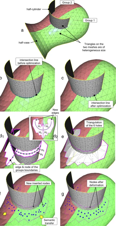
To be able to treat the face/edge merging mode while satisfying the previously introduced criteria, a generic approach is proposed and illustrated on an academic example representing the intersec-tion between a half-vase and a half-cylinder. Two groups of faces are defined on the half-vase (Fig. 4a). The details of the algorithm are given in the next section:
(1) contact interfaces are firstly identified while looking for couples of intersecting faces. The intersection points are then computed and gathered together in a set of intersection lines (Fig. 4b);
(2) intersection lines are then optimized so that the number of nodes as well as their position take into account the size of the surrounding meshes (Fig. 4c);
(3) contact interfaces are cleaned in an n-ring neighbourhood which depends on the size of the surrounding triangles (Fig. 4d1). The boundaries of the groups as well as the
bound-aries of the meshes are preserved. The opened intersection lines are closed by newly inserted edges (Fig. 4d2). The result
is a set of holes that now have to be filled in (6 holes Hiin the
present case);
(4) holes are then triangulated (Fig. 4e) and new points are in-serted to create a smooth evolution of the triangles size (Fig. 4f);
(5) semantic information, corresponding to the groups definition, are reassigned to the newly inserted triangles while propagat-ing the information through the holes boundary (Fig. 4f); (6) inserted meshes are finally deformed to recover the shape of
the interfaces that have been deleted (Fig. 4g).
As described in Section5, the proposed algorithm does not re-quire any action from the user. All the parameters are computed automatically. Therefore, on a user point of view, all the step be-tween theFig. 4a and g are hidden.
5. Details of the algorithms
In the rest of the document, Mesh1 and Mesh2 represent the two meshes that have to be merged.
674 R. Lou et al. / Computer-Aided Design 42 (2010) 670–681
a
b
c
e
f
d
1
d
2g
Fig. 4. Overall merging algorithm on two enriched meshes.
5.1. Contact interfaces detection
This step aims at finding the faces that are potentially in contact. It consists in the detection of intersections between scaled bounding boxes built on each face of Mesh1 and Mesh2 [15]. The
bounding box of a face is computed along the parametric directions and scaled with an empiric factor of 1.05 to avoid inaccuracy problems. It results that the number of detected intersections can be greater than the number of real couples of faces in contact. The outputs of this step are two sets F1and F2containing respectively
a
1
b
c
d
a
2
c
2
c
1
Fig. 5. Intersection line construction.
some faces of Mesh1 and Mesh2. The ith face of F1is potentially
in contact with the ith face of F2. Obviously, since a bounding box
of Mesh1 may intersect several bounding boxes of Mesh2, and vice versa, F1and F2can contain several times the same face.
5.2. Intersection line definition
For each couple of faces
(
f 1,
f 2)
, the intersection nodes between the edges of f 1 and the face f 2 as well as the intersection nodes between the edges of f 2 and the face f 1 are computed. This algorithm is run over the entire sets F1and F2. It results in two setsN12and N21of so-called edge intersection nodes (Fig. 5a1and a2).
See how F1and F2have been built, some couples of faces contained
in F1 and F2 may finally not intersect. Thus, the two arrays are
updated so that they solely contain the faces really intersecting.
The intersection line construction consists in the definition of the edges connecting the initially isolated intersection nodes. It follows two steps:
(1) Locally: creation of edges between edge intersection nodes lo-cated on faces on which there are exactly two edge intersec-tion nodes (Fig. 5b). Since the faces 1 and 2 own more than two edge intersection nodes, the creation of the connections is postponed to the second step. This is performed independently on the two meshes as illustrated on the twoFig. 5c1and c2
de-tailing the local configuration ofFig. 5c. Thus, it gives rise to two sets of potentially disconnected polylines (a set for each mesh); (2) Globally: insertion of the polylines of Mesh1 into the polylines of Mesh2. Depending on a set of identified configurations, the nodes of the polylines of Mesh1 can be inserted in the poly-lines of Mesh2. It may require the creation of new edges. All the nodes are inserted but not all the edges. Actually, solely those edges whose end points are located in the same trian-gle are preserved. Thus, we obtain a set of polylines defined by multiple branches (Fig. 5d).
Actually, this two-steps procedure is mandatory when the den-sities of the two meshes are too different. In this case, it is not pos-sible to build directly all the connections after having merged the whole set of edge intersection nodes.
5.3. Intersection line optimization
As shown in the result of Fig. 4b, the intersection between two meshes may lead to an intersection polyline defined by a non-uniformly distributed set of nodes. This situation is even
more amplified when the mesh densities are significantly different around the contact interface. Since this polyline is used as a basis for the remeshing of the contact interface, it is mandatory to improve the distribution of nodes such that the inserted triangles are as little degenerated as possible. The optimization works in two steps:
(1) so-called particular nodes of the intersection lines are tagged so that they cannot be deleted or even moved during the optimization;
These particular nodes belong to either non-manifold edges, or mesh boundary edges, or group boundary edges or sharp edges (Fig. 6a and c).Fig. 6b shows the result of this step on the previous example.Fig. 6c shows an example where two groups of faces G1and G2have been defined. Thus, the node
arising from the group boundary edge has to be kept to main-tain the semantics potentially associated to the groups (Sec-tion5.6);
(2) deletion of classical nodes, i.e. those nodes that have not been tagged in the previous step, according to the edge average length criterion initialized while computing the average length
`
aof the edges of the triangles that have been identified in thearray F1and F2. The overall algorithm works successively on all
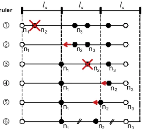
the branches of the interesting lines. The extremities of these branches can either be an extremity of an intersection line, or an edge intersection node on non-manifold edges, or an edge intersection node located on edges to be kept.Fig. 7illustrates the treatment of one branch. It shows a ruler whose basic unit is equal to
`
aand the steps of the optimization process. To easethe understanding of the algorithm, the polyline is here de-ployed and the nodes are spread according to the curvilinear position they have onto the 3D polyline. The ruler is located so that its left extremity matches the 1st extremity. The algorithm optimizes iteratively a segment of two connected edges that are composed by three nodes. If the distance between the first node and the middle node is greater than the average length
`
a, the middle node is moved toward the first node, otherwisethe middle node is removed. If the third node corresponds to another extremity of the optimized branch, the middle node is just moved to the midpoint of the 1st and 3rd nodes. The pseudo-code of this algorithm can be detailed as follows:
To optimize this process, and thus obtained equidistant nodes, one could imagine a second iteration that would move the remaining nodes according to a new target length obtained while computing the average length of the edges remaining in the polyline.
676 R. Lou et al. / Computer-Aided Design 42 (2010) 670–681
a
b
c
Fig. 6. Particular nodes identification with (c) and without (a, b) groups of faces.
Fig. 7. Intersection branch optimization according to the`a average length
criterion. The nodes n1and n6are considered as particular nodes. 5.4. Contact zone cleaning
To prepare the generation of triangles as equilateral as possi-ble, not only the triangles involved in a contact interface have to be deleted, but also those which are in its more or less close neigh-bourhood. This is especially true when the two meshes that have to be merged own very different triangle densities. For a given in-tersection line, potentially defined by one or several branches, the notion of neighbourhood is defined increasingly as follows:
– the first neighbourhood of the polyline, or the neighbourhood at the first order, gathers together all the triangles of the contact interface, i.e. all the triangles contained in F1and F2;
– the second neighbourhood of a polyline gathers together all the triangles defined by at least one node connected to at least one triangle of the first neighbourhood;
– by generalizing, the ith neighbourhood of a polyline gathers together all the triangles defined by at least one node connected to at least one triangle of the
(
i−
1)
th neighbourhood of the polyline. If a polyline has no ith neighbourhood, there will be no neighbourhood of higher order.Given these definitions, it is easy to identify the various neigh-bourhoods of the intersection lines. Thus, to delete the faces included in an n-ring neighbourhood of Nbtriangles around an
in-tersection line (Nb
≥
1), all the triangles of the neighbourhoodshaving an order varying from 1 to Nbare recursively deleted. The
result ofFig. 4d1has been obtained while deleting the triangles in
the first neighbourhood of the intersection line (Nb
=
1) for thehalf-vase and in the second (Nb
=
2) for the half-cylinder.To automatize the instantiation of the control parameter Nb, a
specific algorithm is proposed. It takes into account both the ratio between the densities of the two meshes, which can be more or less equal, and the minimum distance from the intersection line to the boundary of its first order neighbourhood, which can be more or less equal to the half average length
`
a/
2. Depending onwhether the average lengths of the edges of the two meshes are almost equal or not, two different cases are distinguished. In the
first case, i.e. average lengths almost equal, the triangles of both meshes are deleted in an n-ring neighbourhood computed from the analysis of the smallest distance
`
minfrom the intersection lineto the boundary of its first neighbourhood. In the second case, the triangles of the mesh of greatest density are removed in an n-ring neighbourhood equal to 1, whereas the triangles of the mesh of smallest density are deleted in an n-ring neighbourhood defined from the ratio between the half average length
`
a/
2 and thesmallest distance
`
min. This algorithm does not prevent the creationof asymmetric configurations but it tries to minimize them. The algorithm can be written as follows:
The ‘‘Round[x]’’ operator returns the closest integer to the real ‘‘x’’. The function ‘‘Delete[mesh, F, n]’’ deletes all the triangles of ‘‘mesh’’ included in the neighbourhood of order ‘‘n’’ of the intersection line whose first neighbourhood is defined by ‘‘F’’. When computing
`
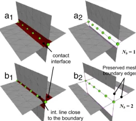
min, the nodes of the intersection line that areon the boundary of the contact interface are not considered. The cleaning algorithm has been run on the two examples depicted on
Fig. 8. Solely the relative position of the two meshes varies from theFig. 8aito theFig. 8bi. The two meshes have the same average
edge length.
Quite similarly to the Section5.3, during the contact faces clean-ing, particular edges are preserved and added to the intersection lines identified in Section5.2. They correspond to either mesh boundary edges, or group boundary edges, or sharp edges or non-manifold edges (Fig. 8b2).
5.5. Contact zone remeshing
Once the contact zone has been cleaned, the newly created holes have to be filled in. The remeshing works in two steps:
a
1
a
2
b
1
b
2
Fig. 8. Contact zone cleaning when merging two meshes having a similar average edge length.
a
b
Fig. 9. Detection of four sub-holes (b) from a unique hole (a).
a
b
Fig. 10. Comparison between the minimum area (a) and the maximum aspect ratio (b) triangulation criteria.
(1) identification of sub-holes that have to be filled in. Starting from the identified and optimized intersection polylines, the extremity nodes are first projected onto the hole contour (closest point algorithm) so that all the intersection lines are closed. On the example ofFig. 9, the two extremity nodes n1
and n2are projected and new edges e1and e2are inserted to
close the intersection lines. Then, the algorithm goes through the polylines data structure to create subsets of polylines forming the contour of sub-holes. On the example ofFig. 9b, four sub-holes are identified.
(2) filling of the sub-holes using an adapted and modified version of Liepa’s algorithm [25] to answer the FE requirements. Given a hole contour, his algorithm builds iteratively a triangulation so that its area is minimum at each step. If this algorithm is ap-plied to the filling of the holes that have been created on the basic example ofFig. 8b2, the resulting triangles are
degener-ated and some others are flat (Fig. 10a). This is due to the fact that Liepa’s area criterion is not adapted to the triangulation of a planar hole (i.e. a hole whose contour is included in a plan). Effectively, on the example ofFig. 10, the area of the created triangulations is constant whatever the admissible configura-tions are. To circumvent these limits, another criterion is here proposed together with its optimization method.
A degenerated triangle is characterized by exactly one or two small angles. To quantify the degeneracy without computing the three angles, we use an indicator introduced to check the quality of FE meshes [26] and defined as follows:
Q
=
α
Shp (1)
where Q is the aspect ratio of a triangle with
α =
2√
3 a normalization coefficient so that Q=
1 for an equilateral triangle,h is the longest edge length, S is the area of the triangle and p its
half-perimeter. This quality factor belongs to the interval [0, 1]. The limit zero corresponds to flat triangles. It is commonly accepted that a triangulation is a good one, with respect to the FE approximation, if the aspect ratio of the worst triangle is greater than 0.5. Being define this indicator, Liepa’s algorithm has been upgraded so that the triangulation maximizes the aspect ratio Q of the triangle inserted at each step (Fig. 10b). For a complete state-of-the-art of hole-filling algorithms, including some comparisons with a precise set of criteria, the reader is encouraged to refer to [27].
5.6. Using and maintaining the semantic information
Semantic information relative to the FE simulation have already been taken into account as constraints in the previous steps. Actually, groups’ boundaries are key elements used to constrain the triangulation (Section 5.5). This is mandatory to be able to reassign to the newly created entities, the semantics surrounding the filled holes (Fig. 4f). In [28], we have demonstrated that this approach can be generalized to groups of dimension 0D (points) to 3D (tetrahedron) that potentially overlap. This is made possible thanks to the concepts of Elementary Group and Virtual Group Boundaries.
Here, the semantics available on the initial mesh are maintained in the resulting mesh. Obviously, this operator does not cover all the needs relative to the manipulation of semantic information when merging two FE meshes. The treatment of configurations involving overlapping groups, groups made of nodes as well as other complex configurations used in industrial FE models are part of our ongoing works. In the future, we would like to investigate on those operators that would enable not only the maintenance and inheritance of the simulation semantics but also their propagation. These operators also have to work on configurations where the semantic information can be a function over the mesh and not only a constant scalar value associated to a group of entities.
5.7. Optimization of the triangulation
To ensure both a good quality of the triangles with respect to the FE criteria, and a smooth blending of the modified area with the surrounding mesh, two additional steps are required:
– insertion of new nodes at the centroid of some triangles and swap
of edges so that the optimized triangulation approximates the
density of the surrounding meshes. This is especially interesting when the two meshes own triangles of heterogeneous sizes in the filled area. The algorithm is an adaptation of [29] so that the swap operation is driven by the aspect ratio Q of the concerned triangles.
– deformation of the filled area so that the connections between the inner and surrounding meshes satisfies either position, tangency or curvature blending conditions. It also relaxes the position of the nodes so that better triangle shapes are obtained. This step fully exploits the work presented in [27]. It is mandatory when the intersection occurs in a non-planar area (Fig. 4g). A linear mechanical model of bars network is used to approximate the curvature evolution between the inserted and surrounding meshes. The deformation is obtained while minimizing a quadratic objective function.
678 R. Lou et al. / Computer-Aided Design 42 (2010) 670–681
a
b
c
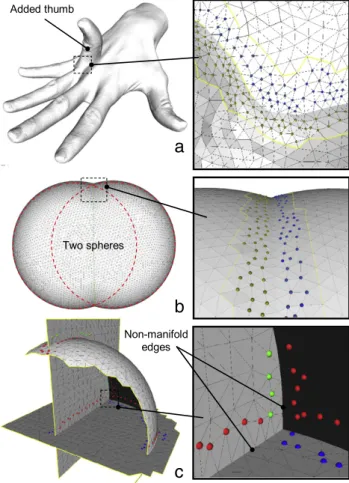
Fig. 11. Merging of two scanned models ((a), courtesy MPII), two spheres intersecting smoothly (b) and an example of non-manifold configuration (c).
Thus, following the modules of Sections 5.5 and 5.7, the holes are filled in while satisfying both a criterion relative to the shape of the deformed triangles (sizes and orientations) and a criterion relative to the quality of the blending between the inserted and surrounding meshes. More precisely, our approach produces a deformation that minimizes the curvature variation over the mesh. The result is obtained while solving a system of linear equations which is interesting on a computational point of view since it is faster than other approaches found in the literature [27].
6. Results and application to FE analysis
The first example shows the merging of the scanned model of a hand with the scanned model of a thumb (Fig. 11a). This re-sult shows that using appropriate thresholds to decide whether the nodes of the intersection line have to be kept or not (Sec-tion5.3), the risk to obtain aliasing effects along the intersection line is minimized. The second example illustrates a configuration where the two meshes intersect smoothly, i.e. with no sharp inter-section (Fig. 11b). The third example is used to illustrate how the developed approach can be used to merge non-manifold meshes (Fig. 11c). First, a part of a sphere is merged with a plane thus pro-ducing non-manifold edges along the intersection line. This model is then merged with a second plane.
Actually, most of the algorithms developed for the face/edge merging mode can be adapted to treat the face/face mode (Fig. 12). In this case, no intersection lines are computed. The contact inter-faces gather together couples of inter-faces that are in a close neighbour-hood. More precisely, two faces belong to a couple of faces when the distance between them is smaller than a threshold, and when the angle between the normals is in between two thresholds. On
a
b
c
Fig. 12. Two scanned stones merged using a similar approach in face/face mode.
the example ofFig. 12, the thresholds are defined by the user. Once these triangles are deleted, the created holes are filled in while us-ing an adapted version of our hole-fillus-ing algorithm. Indeed, in this mode, the holes to be filled in are defined by several boundaries. However, the transfer of semantic information potentially attached to these two meshes is much more difficult in the face/face mode than in the face/edge one. This aspect has not been treated yet.
Table 1gathers together the values of the aspect ratio Q ‘ (min, max and mean) in both the initial and merged configurations of the various examples. It shows that the quality of the merged models is very close to the quality of the initial models which is mandatory when performing multiple and successive operations.
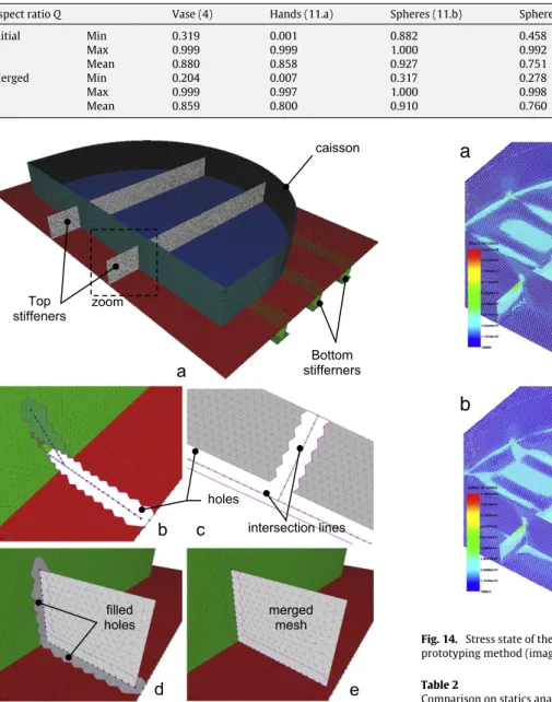
Finally, the proposed approach has been tested and validated on an EDF operational project. More precisely, this caisson had to be rigidified by inserting several stiffeners in the appropriate directions. Fig. 13a represents a possible solution to solve this problem. Both the static and dynamic behaviours of the structure are improved. Fig. 13 shows how the multiple input meshes (Fig. 13a) are treated to obtain a single mesh while keeping intact the semantic information (Fig. 13e). The different colours represent the group assignments. The algorithm first detects the contact interfaces, computes the intersection lines, optimizes the number of intersection nodes and cleans the contact interface (Fig. 13b and c). Here, the meshes are of homogeneous sizes and the cleaned area has an n-ring neighbourhood of one. Thus, for each newly inserted stiffener, 22 holes appear on the caisson and 7 on the stiffener. These holes are then filled in using the newly developed quality criterion (Fig. 13d) and the group assignments are maintained onto the newly created elements (Fig. 13e). The nodes are finally relaxed using our deformation engine [27].
Here, our CAD-less approach is compared to the one which consists in performing the modifications on the CAD model (redesigned starting from scratch):
•
Qualitative comparison of the time necessary to optimize thenumber, the size and the position of the stiffeners. On the one hand, our method requires two main steps: development of the stiffeners 2D numerical model, and merging of the two 2D meshes while maintaining automatically the semantic infor-mation to the resulting mesh. Alternate configurations can be tested directly onto the initial mesh without going back to the CAD model. On the other hand, the use of the classical method requires four steps: design of the caisson’s and stiffeners’ CAD models, assembling of the two CAD models, meshing of the re-sulting CAD model and transfer of the simulation parameters from the ‘‘dead’’ mesh to the new mesh. Since the initial CAD model of the caisson did not exist in this project, the use of the classical method had required its design starting from scratch,
Table 1
Comparison of the aspect ratio Q for the various models.
Aspect ratio Q Vase (4) Hands (11.a) Spheres (11.b) Spheres (11.c) Stones (12) Caisson (13)
Initial Min 0.319 0.001 0.882 0.458 0.005 0.003 Max 0.999 0.999 1.000 0.992 0.995 0.999 Mean 0.880 0.858 0.927 0.751 0.638 0.972 Merged Min 0.204 0.007 0.317 0.278 0.005 0.003 Max 0.999 0.997 1.000 0.998 0.999 0.999 Mean 0.859 0.800 0.910 0.760 0.664 0.968
Fig. 13. Overall merging approach on the example of two stiffeners that have to be merged with a caisson model.
which is a time-consuming task. In addition, the evaluation of different positions and sizes of the stiffeners requires several loops of CAD modifications, meshing, transfer of semantic data which does not tend to reduce the time of the study.
•
Quantitative comparisons of the FE analysis results using Code_ASTER r
[4] for the simulation and SALOME r
[30] to post-process the results. The first results concern the analysis of the mechanical resistance of the structure under exploitation con-ditions. The caisson is subjected to an internal pressure and rigidified using the added stiffeners. Fig. 14a and b show a cartography of the von Mises stress for each of the two pro-totyping methods. Table 2 summarizes the statics analysis results. In both case, the internal pressure of the rigidified cais-son involves a stress concentration phenomenon. Thus, the small difference between the maximal values of equivalent stress constraints evaluated at the geometrical singularity lo-cations was predictable. The von Mises stress at the other loca-tions is very similar in both cases. The maximal relative error, obtained when comparing the stress of the new method to the
a
b
Fig. 14. Stress state of the caisson: (a) case of reference model, (b) case of the new prototyping method (images of SALOME r
, courtesy EDF R&D). Table 2
Comparison on statics analysis results of Code_Aster r
.
Numerical prototyping methods von Mises stress state (MPa)
σmaxon stiffeners
(local stress)
σmaxon caisson wall
Using CAD models 137 78
CAD-less approachC 127 77
stress of the reference solution, is about 7% which is acceptable for fast industrial studies.
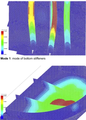
The second results concern the study of the dynamics be-haviour induced by vibration forces due to turning machines usually present on power production centres. Such an analy-sis enables to verify if the locally modified structure does not generate resonance phenomena during its dynamics excitation. TheFig. 15shows some natural modes of the modified cais-son resulting from a modal FE analysis starting from the CAD models.Table 3summarizes the dynamics analysis results. The frequencies obtained using the proposed prototyping method are very close to those of the reference solution. The relative errors between the frequencies computed with the new and older mesh assembly methods are null, which is perfected for operational studies. Moreover, no mode has been lost in the considered band, which is crucial for the analysis of large-size structures in the low-frequency domain.
680 R. Lou et al. / Computer-Aided Design 42 (2010) 670–681
Fig. 15. Examples of caisson natural modes: case of reference mesh (images of SALOME r, courtesy EDF R&D).
Table 3
Comparison of the two modelling strategies on modal analysis results. Natural modes of the structure Frequencies (Hz)
Using CAD models CAD-less approach
1 (triple mode) 114.2 114.2 2 176.8 176.9 3 (triple mode) 209.2 209.2 4 (double mode) 252.0 252.0 5 259.3 259.4 6 (double mode) 268.3 268.3 7 277.4 277.4 8 294.1 294.1
Finally, one can notice that the conform assembly of inde-pendent meshes using the proposed merging method does not introduce complementary specific BCs on the level of the con-nections of the new mesh components to the initial structure, which is another usually used industrial practice. Geometrically conform mesh assembly makes it possible to model accurately the mechanical behaviour of the structure, i.e. to avoid a phe-nomenon of local over/under-rigidification of the structure. The taking into account of meshing quality criteria (e.g. equilateral elements and sufficient smoothness of the mesh) improves the
simulation result that allows converging to the exact solution of the problem. This aspect is critical for operational engineering projects taking into account particular requirements like safety and normal functioning of power product installations.
7. Conclusion
A new approach to the merging of enriched FE triangle meshes has been proposed and validated through a set of industrial test cases. This paper contributes to the specification of a CAD-less ap-proach that does not need to go back to the CAD model during a shape optimization loop. Indeed, the required shape modifications are directly performed onto the FE meshes enriched with semantic information relative to the FE simulation. Thus, not only the geo-metric aspects are taken into account while optimizing the mesh conformity and quality of the produced triangles (shape of the triangles and connections between them), but also the semantic information (e.g. FE groups defining boundary conditions, hetero-geneous materials and link relations) are considered as key pa-rameters used to drive the geometric modifications. Actually, the geometric operators embed some knowledge relative to the way the semantic data have to be treated. In this paper, we pointed out that the boundaries of the FE groups play a key role in the main-tenance of the semantics during the geometric operations. Finally, the merging of the meshes is performed while maintaining the se-mantics potentially associated to a set of groups located in the area to be merged. In this paper, solely the preservation semantic oper-ator is proposed to maintain the semantics during the modification of the geometric model and solely the merging geometric operator is defined and illustrated.
Such high level modification capabilities are of major impor-tance in all the engineering activities requiring fast modifications of meshes without going back to the CAD model. This is especially true in the context of industrial maintenance where the engineers often have to solve critical problems in very short time. Hence, the structural modifications are not anymore performed on the CAD model, but directly on the meshes enriched with simulation semantics. The advantages of such a method have been demon-strated through examples coming from EDF industrial projects. It shows that the newly developed strategy helps the fast prototyp-ing of alternate solutions without havprototyp-ing to think too much to the low level modifications of the CAD models.
Moreover, the proposed approach circumvents the problems that may arise if no CAD model of the structure is available. This happens when the maintenance of the installations/products has to be made by a company different from the one which has designed them.
Finally, we pointed out that a CAD model mainly considers the object as perfect. This does not correspond to the reality that can be measured ‘‘on site’’. When simulating real structures, the FE models (including the meshes) are always tuned to better fit to the physical model (e.g. lasers, accelerometers are used to tune the FE models). Thus, FE models can somehow better capture the ‘‘imperfections’’ of the physical structures. Actually, the gap be-tween the physical and digital mock-up is smaller when consider-ing tuned FE models than with CAD models made of ideal elements (e.g. planes, cylinders). As a consequence, going towards the defini-tion of a CAD-less approach seems promising to be able to perform ‘‘as-built’’ complex simulations.
In the future, we intend to extend this work to the other types of FE mesh. The new research directions concern the definition of manipulation operators working on 3D enriched mesh (e.g. tetrahedral). We foresee to embed inside the operator definition some automatic rules, as well as semi-automatic ones, to capture the knowledge and know-how of the simulation engineers, notably those relative to the transfer of semantics during mesh modifications.
Acknowledgements
This work has been carried out under a Research Contract between the Research and Development Direction of the EDF Group and the LSIS laboratory.
References
[1] Stark J. Product lifecycle management: Paradigm for 21st century product realisation. Springer-Verlag; 2004.
[2] Tichkiewitch S, Brissaud D. Methods and tools for co-operative and integrated design. Kluwer Academic Publishers; 2004.
[3] Shah JJ, Mantyla M. Parametric and feature based CAD/CAM: Concepts, techniques, and applications. New York (NY, USA): John Wiley and Sons, Inc.; 1995.
[4] Code_Aster r
.http://www.code-aster.org/.
[5] Aim@Shape 2004-08. Advanced and innovative models and tools for the de-velopment of semantic-based systems for handling, acquiring, and process-ing knowledge embedded in multidimensional digital objects. European Net-work of Excellence, Key Action: 2.3.1.7 Semantic-based knowledge systems, VI Framework. URL:http://www.aimatshape.net.
[6] Armstrong CG, Monaghan DJ, Price MA, Ou H, Lamont J. Integrating CAE concepts with CAD geometry. In: Topping BHV, Bittnar Z, editors. Engineering computational technology. Saxe-Coburg Publications; 2002. p. 75–104. [7] Hamri O, Léon J-C. Interoperality between CAD and simulation models for
cooperative design. In: CIRP design seminar. 2003.
[8] Hamri O, Léon J-C, Giannini F, Falcidieno B. Using CAD models and their semantics to prepare FE simulation. In: ASME DETC int. comp. in eng. conf. 2005.
[9] Bronsvoort WF, Noort A. Multiple-view feature modelling for integral product development. Computer-Aided Design 2004;36(10):929–46.
[10] Bidarra R, Bronsvoort WF. Semantic feature modelling. Computer-Aided Design 2000;32(3):201–25.
[11] Park SC. Polygonal extrusion. The Visual Computer 2003;19:38–49. [12] Wang CCL, Yuen MMF. Sketch based mesh extrusion with remeshing
techniques. ASME DETC2001/CIE-21305. 2001.
[13] Liu YS, Zhang H, Yong JH, Yu PQ, Sun JG. Mesh blending. The Visual Computer 2005;21:915–27.
[14] Jin X, Lin J, Wang CCL, Feng J, Sun H. Mesh fusion using functional blending on topologically incompatible sections. The Visual Computer 2006;22(4):266–75.
[15] Chouadria R, Véron P. Identifying and re-meshing contact interfaces in a polyhedral assembly for digital mock-up. Engineering with Computers 2006; 22:47–58.
[16] Rose D, Bidmon K, Ertl T. Intuitive and interactive modification of large finite element models. In: Proceedings of visualization’04, p. 361–8.
[17] Smith JM, Dodgson NA. A topologically robust boolean algorithm using approximate arithmetic. In: 22nd European workshop on computational geometry. 2006. p. 217–20.
[18] Graysmith JL, Shaw CT. Automated procedures for Boolean operations on finite element meshes. Engineering Computation: International Journal for Computer-Aided Engineering and Software 1997;14(7):702–17.
[19] Lira WM, Coelho LCG, Martha LF. Multiple intersections of finite-element surface meshes. In: Proceedings of the 11th international meshing roundtable. 2002. p. 355–66.
[20] Jung W, Shin H, Choi BK. Self-intersection removal in triangular mesh offsetting. Computer-Aided Design and Applications 2004;1(1–4):477–84. [21] Park SC. Triangular mesh intersection. The Visual Computer 2004;20:448–56. [22] Coelho LCG, Gattass M, Figueiredo LH. Intersecting and trimming parametric meshes on finite-element shells. International Journal for Numerical Methods in Engineering 2000;47(4):777–800.
[23] Freitag LA, Plassmann PE. Local Optimization-based simplicial mesh untan-gling and improvement. International Journal for Numerical Methods in Engi-neering 2000;49(1–2):109–25.
[24] Shostko AA, Löhner R, Sandberg WC. Surface triangulation over intersecting geometries. International Journal for Numerical Method in Engineering 1999; 44:1359–76.
[25] Liepa P. Filling holes in meshes. In Proceedings of the 2003 Eurographics/ACM SIGGRAPH symposium on geometry processing. 2003. p. 200–5.
[26] Ciarlet PG. The finite element method for elliptic problem. North Holland; 1978.
[27] Pernot J-P, Moraru G, Véron P. Filling holes in meshes using a mechanical model to simulate the curvature variation minimization. Computers & Graphics 2006;30(6):892–902.
[28] Lou R, Giannini F, Pernot J-P, Mikchevitch A, Falcidieno B, Véron P. Towards CAD-less finite element analysis using group boundaries for enriched meshes manipulation. In: Computers and information in engineering conference (ASME DETC2009/CIE-86575). 2009.
[29] Pfeifle R, Seidel HP. Triangular B-splines for blending and filling of polygonal holes. In: Proceedings of graphics interface’96. Morgan Kaufmann Publishers; 1996. p. 186–93.
[30] SALOME r
. Open Source Integration Platform for Numerical Simulation.