is an open access repository that collects the work of Arts et Métiers Institute of
Technology researchers and makes it freely available over the web where possible.
This is an author-deposited version published in:
https://sam.ensam.eu
Handle ID: .
http://hdl.handle.net/10985/7543
To cite this version :
Daniel KERMER, Guillaume FROMENTIN, Olivier LOUTAN, Kossi AGEBEBIADE, Jacques
GIOVANOLA - Micro-orthogonal Cutting of Metals - In: Precision Engineering and
Nanotechnology International Conference, Switzerland, 2008-05-18 - Proceedings of the
European Society for Precision Engineering and Nanotechnology International Conference - 2008
Any correspondence concerning this service should be sent to the repository
Administrator :
[email protected]
Micro-orthogonal Cutting of Metals
D., Kremer1, G. Fromentin2, O. Loutan1, K. Agbebiade1, J. Giovanola1
1
Ecole Polytechnique Fédérale de Lausanne, Switzerland, 2
Arts et Metiers ParisTech, LaBoMaP, Rue Porte de Paris, 71250 CLUNY
Abstract
Industrial application of micro-milling faces several scientific, technological and economic issues. To address these issues, we have developed a micro-orthogonal cutting facility in which chip thickness can be controlled to within a micron and cutting forces can be measured. This paper presents the facility and preliminary results of micro-orthogonal cutting on copper, in the form of span observations, cutting ratio measurements and estimates of shear angles and cutting forces.
1 Introduction
Micro-cutting and in particular micro-milling of ductile metals and more brittle materials has attracted significant attention for its range of potential practical applications in manufacturing of high technology, miniaturized products [1]. Its more wide-spread application hinges upon resolving several scientific, technological and economic issues. Economic and technological issues include the lack of 1) high speed high precision spindles with suitable tool spanning systems capable of achieving high speed cutting conditions and permitting an economical material removing rate, 2) tools with appropriate cutting edge quality and properties, and 3) well documented application databases to select tool geometry and cutting conditions for specific materials. Scientific issues involve among other questions 1) the understanding of the role of characteristic material microstructural dimensions and of cutting edge radius on the cutting size effect and 2) the integration of material damage and separation processes in models of metal cutting.
To address these issues, we are implementing an integrated approach covering from micro-modelling of fracture under predominantly shear loading to developing high speed, high precision spindles. In this paper, we present preliminary results of a basic
investigation of micro-orthogonal cutting of metal aiming at 1) understanding and modelling micro-cutting processes, 2) identifying size effects by comparison with macro-cutting results and 3) assessing the transferability of macro-cutting data to micro-cutting.
2 Micro-orthogonal cutting facility.
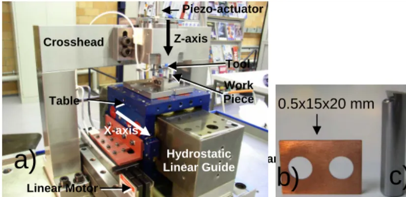
Figure 1 shows the micro-orthogonal cutting facility (a), the specimen (b), and the cutting tool (c). The X-axis consists of a hydrostatic linear guideway with a electrical linear motor. The detailed kinematic, static and dynamic characterizations of the system are still underway. Available results can be summarized as follows. The transverse stiffness of the X-axis is greater than 250 N/μm for a supply pressure of 10 bars. The stroke is 100 mm with a maximum speed of around 1.2 m/s (over 20 mm) with peak accelerations of approximately 3g. Estimates and measurements indicate maximum dynamic yaw and tilt displacements at the table edges on the order of ± 3 μm for an acceleration of 3 g and a supply pressure of 10 bars. A piezo-actuator controls the Z-axis position (± 250 nm) and the depth of cut by means of an Eddy current sensor and a feedback control loop. Currently the control of the span thickness is better than ± 1 μm, all error sources included. The Z-axis also provides a measurement of the Z cutting force through the control voltage of the piezo actuator or a separate force sensor. Another sensor, built, but not tested, will measure X cutting forces.
Figure 1 a) Micro-orthogonal cutting facility b) specimen c) WC tool
Hydrostatic Linear Guide Table X-axis Work Piece Tool Z-axis Crosshead Piezo-actuator
a)
Hydrostatic Linear Guide Linear Motorb)
c)
0.5x15x20 mm
3 Results of preliminary orthogonal cutting experiments.
We performed orthogonal cutting experiments on copper specimens with the facility of Figure 1, varying depth of cut hc (5 and 10 μm), rake angle γ (20°, 0°, -20°) and
cutting speed vc (440, 660, 880 mm/s). For these experiments, we characterized the
morphology and dimensions of the span and the roughness of the specimen surface; we determined the cutting ratio and estimated the cutting forces. In separate experiments we also performed proof-of-concept measurements of the Z thrust force and photographed the formation of the span. Figures 2 to 4 and Tables 1 and 2 illustrate the results of these experiments.
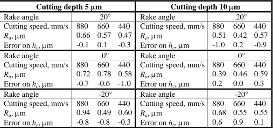
Table 1: Roughness Ra and cutting depth accuracy as a function of cutting parameters
Cutting depth 5 μm Cutting depth 10 μm
Rake angle 20° Rake angle 20°
Cutting speed, mm/s 880 660 440 Cutting speed, mm/s 880 660 440
Ra, μm 0.66 0.57 0.47 Ra, μm 0.51 0.42 0.57
Error on hc, μm -0.1 0.1 -0.3 Error on hc, μm -1.0 0.2 -0.9
Rake angle 0° Rake angle 0°
Cutting speed, mm/s 880 660 440 Cutting speed, mm/s 880 660 440
Ra, μm 0.72 0.78 0.58 Ra, μm 0.39 0.46 0.59
Error on hc, μm -0.7 -0.6 -1.0 Error on hc, μm 0.2 0.0 0.3
Rake angle -20° Rake angle -20° Cutting speed, mm/s 880 660 440 Cutting speed, mm/s 880 660 440
Ra, μm 0.94 0.49 0.60 Ra, μm 0.68 0.55 0.55
Error on hc, μm -0.8 -0.8 -0.3 Error on hc, μm 0.6 0.9 0.1
The thickness of material removed hc varies at most by 1 μm, independently of the
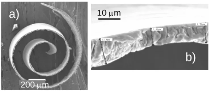
cutting parameters investigated, showing that we have a good control of the depth of cut. The resulting roughness of the specimen surface does not follow any clear trend with varying cutting parameters and ranges between 0.39 and 0.94 (Table 1). Micro-spans look rather similar to their macroscopic counterparts, except for their small size. Spans produced by a tool with γ = 20° are strongly curled up whereas spans associated with the other 2 rake angles are almost flat (Figures 2 and 3). The thickness of the cut span hs can vary by several μm along its length (Figure 2b). The
reason for this variation is not known yet.
Spans vary in width too (Figure 3a). Whereas the surface sliding on the rake face is rather smooth – showing only the grooving pattern caused by the roughness of the
rake face – the free surface is strongly serrated with the size and the spacing of the serrations varying along the span length, and also as a function of cutting parameters (Figure 3a). The serrations or folds are more pronounced for a negative rake angle and their structure changes with cutting speed (Figure 3b).
Figure 2 SEM photographs of a copper span a) overall view, b) edge view showing thickness variations (hc < 5 μm, γ = 20°).
The cutting ratios Rc estimated on the basis of the depth of cut and span thickness
measurements range from about 0.08 to 0.13 for γ = -20° and 0°, and 0.19 to 0.22 for γ = 20°. The cutting ratio is not very sensitive to vc (Figure 4).
Using the measured cutting ratios and the Lee and Shaffer model [2], one can
Figure 3 Span appearance a) overall view (hc= 10 μm, vc=440 mm/s, γ = -20°);
b) fold appearance on span surface as a function of vc and γ.
10 μm
200 μm
a)
b)
Large serrations 500 μm 20° -20° 20 μm Small serrations 880 mm/s 440 mm/sa) b)
Figure 4 Cutting ratio as a function of vc and γ (hc=10 μm).
estimate shear angles and cutting forces. With a flow strength of 270 MPa for copper and hc=10 μm, we obtain the data in Table 2. Preliminary direct measurements of
the Z-axis repelling force for γ = 20° and hc=10 μm give values in the range 4 to 6 N.
Table 2: estimates of cutting parameters (hc=10 μm)
Rake angle γ [°] 20 0 -20
Cutting ratio Rc 0.19 – 0.22 0.08 – 0.13 0.08 – 0.09
Shear angle φ [°] 10.8 – 12.6 4.5 – 7.4 4.2 – 4.7 X-force [N] 8.4 – 7.4 18.2 – 11.7 19.8 – 17.8 Z-force [N] 5.7 – 4.7 15.5 – 9.0 17.1 – 15.1
4 Summary and perspectives
An experimental platform for investigating micro-cutting has been developed and its performances have been partially validated. Encouraging preliminary cutting data have been obtained for copper. Work continues to characterize fully dynamic behaviour and precision of the facility, and to integrate reliable sensors for measuring cutting forces. Additional work will focus on developing cutting tools with sharper and more regular cutting edges and on demonstrating the importance of material separation processes in controlling cutting forces.
References:
[1] Masuzawa, T., “State of the Art of Micromachining” Annals of CIRP, 49, 2, (2000), p. 473.
[2] Oxley, P.L.B., The Mechanics of Machining, Ellis Horwood, Chichester, (1989).
Rake angle ° Rc