Science Arts & Métiers (SAM)
is an open access repository that collects the work of Arts et Métiers Institute of
Technology researchers and makes it freely available over the web where possible.
This is an author-deposited version published in: https://sam.ensam.eu Handle ID: .http://hdl.handle.net/10985/13796
To cite this version :
Tiago José DOS SANTOS MORAES, Eric SEMAIL, Ngac Ky NGUYEN, Fabien MEINGUET, Mael GUERIN New Electrical InversedSeries Connection for EvenPhase Symmetrical PMSMs -IEEE Transactions on Power Electronics - Vol. 33, n°9, p.7938 - 7947 - 2018
Any correspondence concerning this service should be sent to the repository Administrator : archiveouverte@ensam.eu
New Electrical Inversed-Series Connection for Even-Phase
Symmetrical PMSMs
Tiago José dos Santos Moraes
1, Student Member, IEEE, Eric Semail
1, Member, IEEE, Ngac Ky Nguyen
1, Member,
IEEE, Fabien Meinguet
2, Mael Guerin
3,
1Univ. Lille, Centrale Lille, Arts et Métiers ParisTech, HEI, HeSam, EA 2697 –
L2EP - Laboratoire d’Electrotechnique et d’Electronique de Puissance, F-59000 Lille, France
2
Thales Alenia Space, Charleroi, Belgium
3
Thales Avionics Electronics System, Chatou, France
E-mail: 1{tiago.dossantosmoraes; ngacky.nguyen; eric.semail}@ensam.eu
2
fabien.meinguet@thalesaleniaspace.com
3
mael.guerin@fr.thalesgroup.com
Abstract—This paper presents an extension of previous
methods in order to find electrical series-connections between multiphase machines allowing the independent control of each one of them. These new electrical series-connections explore the symmetrical disposition of the phases of even-multiphase machines, allowing the inversed connection of some of the phases, different from the direct connections as it was previously done. Therefore, electrical series-connections of two symmetrical 6-phase or of four symmetrical 10-6-phase machines are now possible. Besides that, this new solution ensures a natural independent control of permanent magnet synchronous machines even if the back-electromotive forces generated by the rotor are not sinusoidal, without need of special machine conception or supplementary control strategy. This control independency is mathematically proved using the decomposition of multiphase machines in fictitious diphase and homopolar machines. Experimental results are presented to show the functioning and the advantages of this new coupling for two symmetrical 6-phase permanent magnet synchronous machines.
Keywords—series-connection; PMSM; multi-machine; even-phase machine;
NOMENCLATURE
� : Phase shift angle s : Phase shift factor
� : Number of phases of the machine � : Number of machines
� : Current of each phase “j”
�ℎ : Current amplitude of the hth harmonic
ℎ : Harmonic rank � : Electric speed
� ℎ : Harmonic “h” phase shift between phases
[� ] : Concordia matrix for a “n”-phase machine [ ] : Current vector of machine “m”
[��] : Coupling matrix for a phase shift factor “s”
[ ] : Current vector in αβ subspace of fictitious machine “fm” [ � ] : Current vector in dq subspace of fictitious machine “fm”
PMSM : Permanent Magnet Synchronous Machine FM : Fictitious machine
I. INTRODUCTION
Multiphase machines are being increasingly used in different applications because of their advantages such as power sharing per phase and high torque density with low torque ripple, and mostly because of their inherent fault tolerance capability [1] and [2]. This capability is highly recommended or compulsory for some applications in aeronautics, aerospace, naval, electric vehicles and offshore wind turbines. Besides the listed advantages, these machines need a higher number of transistors in the Voltage Source Inverter, thus increasing the weight, volume and cost of the drive [3]-0.
When several machines must be controlled simultaneously, there is one possibility to solve this constraint by using a particular property of multiphase machines; the ability to be controlled independently even if they are series-connected. Series-connection is a solution for reducing the number of transistors [7]-[8] in applications with several multiphase machines. Some advantages of this solution in fault-tolerant applications, like peak-currents and torque ripple are reported in the literature [7]-[9]. However, the copper losses increase because the currents that generate torque in one machine flow in all machines. Nevertheless, in systems like airplanes, drones and rockets, the system weight reduction, due to the motors’ series-connection, can compensate the increase of the motors’ losses, when analyzing the global efficiency.
Initial literature on series-connected machines have been published for induction odd-phase machines in [10]-[16], with experimental results in [16], for synchronous machines with sinusoidal electromotive force in [17]-[18], and experimental results in [14]. In the case of non-sinusoidal Back-EMF [19]-[20] propose a supplementary decoupling by control and [19]-[20] gives experimental results.
In order to ensure the independent control of the machines, the drive must fulfill some rules. The system must have enough degrees of freedom (DoF) to control all the machines that are series-connected (2 DoF per machine) and at least one
supplementary DoF to ensure the control of the machines in degraded mode. The number of DoF is directly related to the machine’s number of phases. A special coupling between the machines is necessary in order to decouple the control of the series-connected machines. The independent control of each machine consists in imposing current components in order to generate torque in one machine but not in the others, even if the currents flow in all the series-connected machines.
In [14], [21] and [22], a method to obtain series-connections between the machines ensuring the decoupling of the machines’ control was demonstrated. This method is applicable to different odd-phase machines. After some adaptations and extensions of the method, a few connections between even-phase machines are also obtained: connections between two 8-phase and three 10-phase symmetrical machines [21], connection between “2n”-phase machine to an “n”-phase machine [21]-[29] and connection between asymmetrical even-phase machines [22] and [29].
However, it has never been shown in the existing literature how to connect two symmetrical 6-phase machines with their independent control. This particular case is practically of importance because it is easy to obtain a symmetrical 6-phase machine from a 3-phase machine without special design. It is only necessary to modify internal connection of windings in order to extract three supplementary connection terminals. Moreover the fact to be able to use identical machines is also of interest. It is the case with the methodology which is presented in this paper. This methodology allows also supplementary connections which could be interesting when the connected machines must be identical, as four symmetrical 10-phase machines.
Concerning PMSM whose back-EMF are not sinusoidal, the classical series-connections between the machines are not sufficient to ensure their independent control. In this case, the design of a PMSM rotor nullifying some Back-EMF harmonics or a special control, as presented in [17], are also necessary. However, for the connection presented in this paper, the control independency can be ensured without special control and with much less rotor dimensioning constraints. The mathematical demonstration is presented in Section IV.
The paper is organized as follows. Section II explains the method already presented in the literature. Section III extends this method by adding the “inversed” connection between phases. Section IV demonstrates the decoupling of the machine’s control by the representation in fictitious machines (FMs) method, showing that the inverted connection allows a natural decoupling of regular series-connected PMSMs, even if the Back-EMF are not sinusoidal. Finally, section IV presents some experimental and simulation results before the conclusion.
II. REGULAR PHASE SWAPPING
A method which allows the connection of “N” “n”-phase machines in series, if the number of phases “n” is higher than “2N+1” is presented in [14], [21] and [22]. This method consists in directly connecting the phase 1 of M1 to the phase 1
of M2, then connecting the phase 2 of M1 to the phase 3 of M2, transposing it to an angle (α12) equal to 2π/n. For each
subsequent phase, the transposing angle is incremented by 2π/n. Phase 3 and 4 of M1 are respectively transposed by an angle of 2α12 and 3α12.
In order to connect three machines in series, the machines should have at least 7 phases. Machines M2 and M3 are connected as explained above, with a transposing angle (α23) of
2π/n. Consequently, the transposing angle between M1 and M3 is 4π/n. The same is done if more machines are series connected. The fact that all the machines that are connected in series are independently controlled shows that the transposing angle can be a multiple of 2π/n. Therefore it is possible to assert that the transposing angle (α) is defined by equation (1), in which “s” is a constant and integer value.
� = − �� (1)
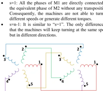
The phases of a rotating machine are cyclically distributed and any angle “α” is exactly the same as “α±k2π”, being “k” an integer number. This can be seen in Fig. 1, in which there are two 5-phase machines connected in series with “s=3”. Phase 4 of M1 is supposed to be transposed by an angle of “12π/5”, but in the end it is only transposed by “2π/5” as well as connected to phase 5. In the same way, when the connected phase “j” is higher than the number “n” of phases of the machines, the real connected phase is “j-kn”. Because of that, the only values that are analyzed for “s” are between “1” and “n”, any other “s” value is redundant. For example, “s=2” and “s=n+2” result in the exactly same connection between the machines.
TABLE I shows the connection between M1 and M2 for different values of “s”.
Just by looking at this table it is possible to determine that some values of “s” are not worth analyzing in more details.
s=n: Only one phase of M2 is supplied. M2 is not able to turn.
s=1: All the phases of M1 are directly connected to the equivalent phase of M2 without any transposition. Consequently, the machines are not able to turn at different speeds or generate different torques.
s=n-1: It is similar to “s=1”. The only difference is that the machines will keep turning at the same speed but in different directions.
3 4 5 2 5 4 3 2 1 1
Fig. 1. Scheme showing the electric shift angle between the phases of two 5-phase machines connected in series for “s=3”.
TABLE I. Different series-connection for two “n”-phase machines. s 1 2 3 … x … n-2 n-1 n Phases of M1 Phases of M2 1 1 1 1 … 1 … 1 1 1 2 2 3 4 … 1+x … n-1 n 1 3 3 5 7 … 1+2x … n-3 n-1 1 ⁞ ⁞ ⁞ ⁞ ⋱ ⁞ ⋱ ⁞ ⁞ ⁞
y y 2y-1 3y-2 … x(y-1)+1 … n-2y+3 n-y+2 1
⁞ ⁞ ⁞ ⁞ ⋱ ⁞ ⋱ ⁞ ⁞ ⁞
n-2 n-2 n-5 n-8 … n-3x+1 … 7 4 1
n-1 n-1 n-3 n-5 … n-2x+1 … 5 3 1
n n n-1 n-2 … n-x+1 … 3 2 1
TABLE II. DIFFERENT SERIES-CONNECTIONS FOR TWO 6-PHASE MACHINES. s 2 3 4 Phases of M1 Phases of M2 1 1 1 1 2 3 4 5 3 5 1 3 4 1 4 1 5 3 1 5 6 5 4 3
TABLE III. DIFFERENT SERIES CONNECTIONS FOR TWO 7-PHASE MACHINES. s 2 3 4 5 Phases of M1 Phases of M2 1 1 1 1 1 2 3 4 5 6 3 5 7 2 4 4 7 3 6 2 5 2 6 4 7 6 4 2 7 5 7 6 5 3 3
By eliminating the values of “s” that are not interesting, “s” may be any integer value between 2 and “n-2”. In TABLE II and
TABLE III, all the possible connections between two symmetrical 6-phase and two symmetrical 7-phase machines are presented.
Concerning the 7-phase machines, there is no special comment because all possible connections may be implemented. All the “s” values presented allow an independent control of each machine. This independency is demonstrated in section IV, as the impact on the topology’s behavior by choosing each different value of “s”. Otherwise, TABLE II shows that for any of the three “s” values it is not possible to connect them in a way in which all the 6 phases of M2 are supplied. This happens when “s” has a common divisor with “n” and this is the case for all the possible “s” values for the 6-phase machines. Because of this, the previous works mostly took into account odd-phase machines and the connection obtained by “s=2”. 1 2 3 6 5 4 1 2 3 6 5 4
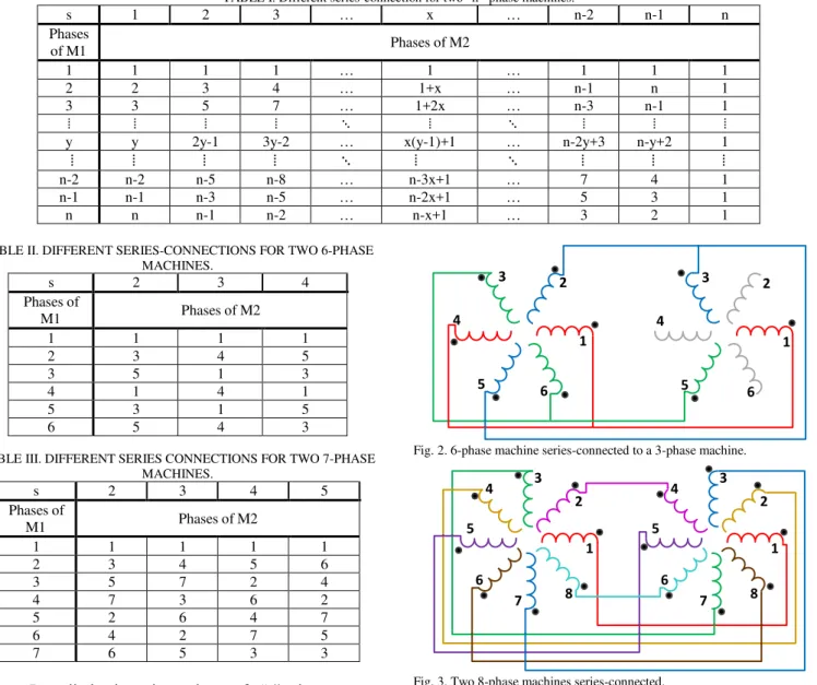
Fig. 2. 6-phase machine series-connected to a 3-phase machine.
1 2 3 6 5 4 7 8 1 2 3 6 5 4 7 8
Fig. 3. Two 8-phase machines series-connected.
It is also possible to see that the value of the great common divisor (GCD) of “s” and “n” is the number of phases of M1 connected to the same phase of M2. For example, for the connection “s=2” for two 6-phase machines, 2 is the GCD of 6 and 2, which are the values of “n” and “s” respectively; there are 2 phases of M1 connected to each phase of M2. That is why [21]-[29] propose a connection of a 6-phase machine (M1) to a 3-phase machine (M2), in which the phases of M1 are connected two by two to each phase of M2 (Fig. 2).
It does not mean that there is no possible connection between even-phase machines in the literature. In [21], a connection between two 8-phase machines is presented (Fig. 3). Even if it is not explained with the same method as this paper, the connection shown is for an “s=3”, instead of “s=2” as it was usually the case at the time.
III. INVERSED SERIES CONNECTION
This paper presents another solution to connect the machines with symmetrical even-phase machines. Thanks to its symmetry, supplying a phase “j” of the machine is magnetically identical to supplying the phase “j+n/2” with the symmetrical current (equation (2)). Consequently, instead of direct connecting (Fig. 4) two phases of M1 to the same phase “j” of M2, one of these two phases of M1 is inversely connected (Fig. 5) to the phase “j+n/2” of M2.
Taking into account the inversed connection, it is possible to update TABLE II, obtaining TABLE IV. The values of “s” with a “*” represent the ones in which there are inversed connections, which are represented by the “-” signal in front of the number of the phase of M2.
The inversed connection of phases cannot be implemented to “s=3” because there are 3 phases of M1 connected to each supplied phase of M2. Besides that, these only 2 phases of M2 connected to M1 are shifted by π. These represent the 2 compulsory conditions in order to implement the inversed connection:
1. The phases of M1 have to be connected two by two to the phases of M2, what only happens when the GCD of the number of phases “n” and “s” is 2.
2. The opposite phases, shifted by π, should not be connected, so the number of phases “n” should not be divisible by 4.
For the second condition, a better example is two 8-phase machines series-connected with “s=2” (Fig. 6). In this case, condition 1 is respected, the phases of M1 are connected two by two with the phases of M2, but condition 2 is not verified.
Otherwise, the inversed connection can be implemented to10-phase symmetrical machines with “s=2”. Then is possible to series-connect four 10-phase machines.
Fig. 4. Direct connection between two phases.
Fig. 5. Inversed connection between two phases.
TABLE IV. DIFFERENT SERIES-CONNECTIONS FOR TWO 6-PHASE MACHINES TAKING INTO ACCOUNT THE INVERSED CONNECTION.
S 2 2* 3 3* 4 4* Phases of M1 Phases of M2 1 1 1 1 1 1 2 3 -6 4 5 -2 3 5 5 1 3 3 4 1 -4 4 1 -4 5 3 3 1 5 5 6 5 -2 4 3 -6 1 2 3 6 5 4 7 8 1 2 3 6 5 4 7 8
Fig. 6. 8-phase machine connected to a 4-phase machine.
IV. FICTITIOUS MACHINES (FM) COUPLING
The FM representation is a tool to demonstrate the independency control between series-connected machines. It consists in decomposing a multi-phase machine on 2-phase and homopolar (1 phase) mathematically decoupled FMs [12] [31]. The torque generated by the real machine is the sum of the torques generated by each FM, knowing that the 2-phase FMs are able to produce a constant torque as the homopolar ones are not. In normal mode, each FM interacts with some harmonics, being the main machine a 2-phase FM that generates torque with the fundamental back-EMF and current. Therefore, controlling only the main machine is possible to generate a constant torque with the minimal current (MTPA – Maximum Torque Per Ampere strategy). The parameters and the variables of each FM, as currents or voltages, are obtained by using the Concordia transformation.
For a symmetrical “n”-phase machine, harmonics are distributed as shown in TABLE V. The harmonics that interact with the same machine have a common shift angle between two adjacent phases (� ℎ). This shift angle is obtained by equations (1) and (2). Each harmonic may have a shift angle in comparison to the fundamental harmonic. In order to simplify equation 0 and because this shift angle is not important to the following analysis, this phase shift is neglected.
The machine’s phase currents may be represented as follows:
�= ∑ �ℎcαs ℎ (� + − � )� ℎ=
(3) in which the shift angle between two adjacent phases is:
ϕnh= h nπ (4)
TABLE VI and TABLE VII represent the harmonic distribution and the shift angles for a 6-phase and a 7-phase machine as examples.
When two multiphase machines are series-connected, the fictitious machines are also coupled. Therefore, two major conditions have to be respected in order to obtain the independent control of the machines:
Ensure that the main machines are decoupled from each other;
Ensure that the FM to which the main machine is coupled does not generate torque;
No t P o ss ib le
TABLE V. HARMONIC DISTRIBUTION OF THE FMS OF A SYMMETRICAL “N”-PHASE MACHINE. FM Harmonics ��� Main ; � − ; � + ; … � ± ± � � 2nd ; � − ; � + ; … � ± ± � � ⁞ ⁞ ⁞ �th �; � − �; � + �; … � ± � ±x π n ⁞ ⁞ ⁞ “�/ − ” th �/ − ; �/ + ; �/ − ; … � ± �/ − ± n− π n “�/ − ” th �/ − ; �/ + ; �/ − ; … � ± �/ − ± n− nπ Homopolar 1 �; �; … � Homopolar 2
(only for even-phase machines) �/ ; �/ ; … � ± �/ �
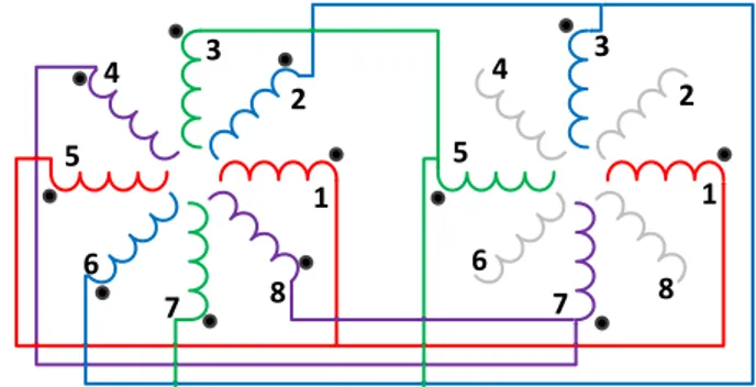
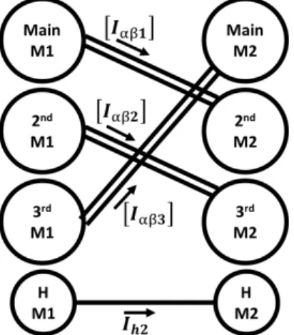
Papers [7], [12] and [27] have already shown how the FMs or subspaces are coupled for different connections and different number of phases. Equations (5) to (13) represent mathematically by matrixes the coupling of two symmetrical 6-phase machines (Fig. 7).
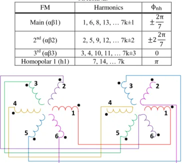
TABLE VI. HARMONIC DISTRIBUTION OF THE FMS OF A 6-PHASE MACHINE. FM Harmonics ϕnh Main (αβ1) 1, 5, 7, 11, … 6k±1 ± � 2nd(αβ2) 2, 4, 8, 10, … 6k±2 ± � Homopolar 1 (h1) 6, 12, … 6k ± � Homopolar 2 (h2) 3, 9, … 6k±3 0
TABLE VII. HARMONIC DISTRIBUTION OF THE FMS OF A 7-PHASE MACHINE. FM Harmonics ϕnh Main (αβ1) 1, 6, 8, 13, … 7k±1 ± π 2nd(αβ2) 2, 5, 9, 12, … 7k±2 ± π 3rd(αβ3) 3, 4, 10, 11, … 7k±3 0 Homopolar 1 (h1) 7, 14, … 7k � 1 2 3 6 5 4 1 2 3 6 5 4
Fig. 7. Two 6-phase machines series-connected with “s=4*”.
[�6] = √ [ cαs( �) cαs(�) sin( �) sin( �) cαs( �) cαs(�) − cαs( �) cαs( �) sin( �) sin( �) cαs( �) cαs( �) sin( �) sin( �) √ √ √ √ −√ √ sin( �) sin( �) √ √ √ −√ √ −√ ] (5) [M ] = [ ][M ] (6) [K4∗] = [ − − − ] (7) [ M ] = [�6][ 4∗]− [�6]�[ M ] (8) [ M I M I M I M Ih M Ih M ] = [ − − ][ M I M I M I M Ih M Ih M ] (9) [ ] = [ ] = [ � � ] = [ � − � ] (10) [ ] = [ ] = [ � � ] = [ � − � ] (11) ℎ � = ℎ � (12) ℎ � = ℎ � (13)
Fig. 8. Couplings between two 6-phase’ FMs for “s=4*”. 1 2 3 6 5 4 7 1 2 3 6 5 4 7
Fig. 9. Series-connection for two 7-phase machines for “s=2”.
Fig. 10. Couplings between two 7-phase’ FMs for “s=2”.
TABLE VIII. COUPLINGS BETWEEN TWO SERIES CONNECTED 7-PHASE’S FMS FOR DIFFERENT “S” VALUES
s=2 s=3 s=4 s=5
Main M1 2nd M2 3rd M2 3rd M2* 2nd M2* 2nd M1 3rd M2* Main M2* Main M2 3rd M2 3rd M1 Main M2* 2nd M2 2nd M2* Main M2
H M1 H M2 H M2 H M2 H M2
Analyzing the equations, especially (10) to (13), the coupling of the FMs is obvious, schematized by Fig. 8. Fig. 9 and Fig. 10 also show the coupling between two 7-phase machines and their FMs as well. In both cases, the decoupling of the main machines is achieved. The currents of a main machine drive a 2nd or a 3rd machine.
Each “s” value represents a different coupling between the FMs. TABLE VIII shows the different couplings for each “s” value for two 7-phase machines connected in series.
The asterisks (*) in TABLE VIII represents that the two FMs are coupled in series, but the current of one is the conjugate of the other, not exactly the same. However, no practical difference or advantage has been noticed until now between these two cases. Otherwise, considering a different coupling between the FMs, it is recommended to choose the connection in which the main machines are coupled to other FMs that have low back-EMF amplitude, in order to reduce a possible torque ripple.
As the machines are not totally decoupled, to obtain the independent control of each machine, the 2nd or 3rd machines may not generate torque. There are two solutions in order to respect this condition: control strategy or machine design. The first is described in [19] and [20], in which a control strategy is developed in order to compensate the torque oscillation generated by the FM coupled to the main machine. The second one consists in eliminating the back-EMFs’ harmonics that interact with the FM coupled to the main machine during the electric machine’s design. This is the reason why induction machines were studied in series-connected topologies before PMSM. The back-EMF of induction machines is induced by the stator currents, which are controlled.
The elimination of some FMs’ harmonics during the machine design may seem expensive. In PMSM, the back-EMF harmonics depends on the rotor architecture. Therefore, a special architecture with specific industrial constraint is needed in order to nullify the 3rd or the 5th back-EMF harmonics, depending on the coupling between the fictitious machines. But, in the case of two symmetrical even-phase machines, a regular symmetrical PMSM rotor ensures that the Back-EMF of the FM coupled to the main machines is null.
TABLE VI shows that the secondary machine of a 6-phase machine only interacts with even harmonics. As back-EMFs’ even harmonics are null because of the rotor’s symmetry, those FMs are not able to generate torque. Consequently, in the case presented on Fig. 8, the control of both machines connected in series is naturally independent. This is not the case for two 7-phase machines connected in series, because all the FMs interact with odd and even harmonics, so they can all potentially generate torque.
� = ∑ Ahcαs ℎ (� + − � )� ℎ= (14) �nh = ℎ � = �� nh (15) � = ∑ ℎ1cαs ( ℎ ( � + − � ± −� ⏞ � �� ) ± − �⏞ ) ℎ1= (16)
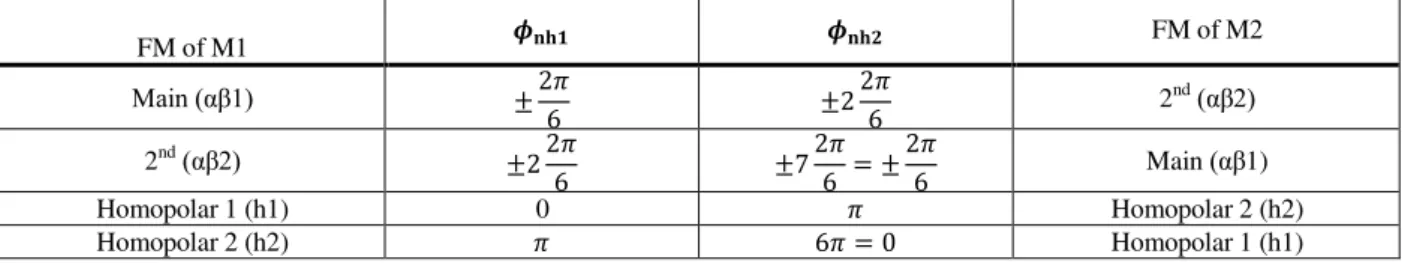
TABLE IX. COUPLINGS BETWEEN TWO 6-PHASE’ FMS FOR “S=2”, OBTAINED BY PHASE SHIFT ANGLE ANALYSIS. FM of M1 ��� ��� FM of M2 Main (αβ1) ± � ± � 2nd (αβ2) 2nd (αβ2) ± � ± �= ± � Main (αβ1) Homopolar 1 (h1) 0 � Homopolar 2 (h2) Homopolar 2 (h2) � � = Homopolar 1 (h1)
When coupling two regular even-phase machines with an even “s” connection, the machines’ control is naturally decoupled. The series-connection between the machines swaps mechanically the phases in order to couple different FMs. Equations (14) and (15) show how to obtain the phase shift angle for M2, depending of the harmonic current of M1.
It is possible to re-obtain TABLE VIII using TABLE VII and equation (15) for different values of “s” for 7-phase machines.
If the same procedure is done to a coupling with inversion connections, two expressions have to be added to the equation of the currents of M2. Expression (A) represents the shift of n/2 phases and expression (B) represents the inversed connection in equation (16).
In that case the phase shift of M2 is defined by equation (17):
�nh = +� ℎ � + � =� ±� � ± � (17)
For “s=2” and two 6-phase machines we have the connection as seen below.
Generalizing to the case in which the inversed connection is applied:
“s” is an even number;
“n” is an even number not divisible by 4, then “n/2” is an odd number;
�nh = ±� �� (18)
�nh = ± +� � +� �� (19)
By analyzing equations (18) and (19) it is possible to obtain TABLE X.
TABLE X. RELATION BETWEEN ��� AND ���.
� +� � +�
odd even
even odd
TABLE X shows that an only odd-harmonics FM of M1 is always coupled to an only even-harmonic FM of M2 and vice versa. Besides, the coupling between the harmonic FMs is also obtained by replacing “x” with “0” or “n/2”. This confirms that, in the conditions mentioned above, the control of the series-connected machines is naturally decoupled.
Concerning more than two machines connected in series, it is not possible to affirm that all machines are naturally
decoupled. Considering that all M1 odd-harmonics FMs are connected to even-harmonics FMs of M2 and vice versa. The harmonics of M3 definitely are coupled to the odd-harmonics FMs of M1 or M2. Anyway, it is possible to connect four symmetrical 10-phase machines, in a way in which each main machine is decoupled from the others.
V. EXPERIMENTAL RESULTS
With the test bench presented in Fig. 11, experimental results were obtained in order to demonstrate the control independency of two symmetrical 6-phase PMSM series-connected supplied by classical 6-leg inverter as shown in scheme of Fig. 12. The two PMSM are identical (the parameters are listed in
Table XI) with an almost sinusoidal back-EMF. Its 3rd, 5th and 7th harmonics are respectively 1.73%, 0.9% and 0.2% of the fundamental one.
1A 1B 1C 1D 1E 1F 1'A 1'B 1'C 1'D 1'E 1'F i1a i1b i1c i1d i1e i1f 2A 2B 2C 2D 2E 2F 2'A 2'B 2'C 2'D 2'E 2'F i2a i2b i2c i2d i2e i2f VDC1 N1 M1 M2 VSI1 T 1 T 7 T 2 T 8 T 3 T 9 T 4 T 1 0 T 5 T 1 1 T 6 T 1 2
Fig. 12: Scheme of the tested drive.
Fig. 13 shows the control scheme of the machine. Regular PI controllers are used to control the speed of each machine and the currents of each fictitious machine. As the main machine of M1 is series connected to the secondary machine of M2 and vice-versa, it must take into account the equivalent resistance and cyclic inductance, the sum of the resistances and cyclic inductances of both fictitious machines series connected, in order to define the current PI corrector parameters by classical method, as tuning by pole cancellation. Only the currents of each main machine are controlled as the reference voltage of the homopolar machines is null.
The speed profile chosen to demonstrate the control independency between the machines is one machine controlled with constant speed while the other has a trapezoidal profile. Fig. 14 shows the measured speed of both machines. It is possible to notice that the variation of speed of M2 has no impact on M1, hence representing the independency of each machine’s control.
Fig. 13. Control scheme of two 6-phase machines series-connected. Table XI: Machines parameters.
Resistance: � 0.77Ω Fictitious machine inductance: 9,16mH 9,06mH ℎ 5,0mH ℎ 0,7mH Torque constant: 1V/rad/s
Inertia constant: 0,01kg.m² Friction coefficient: � 0,01Nm/rad/s
Fig. 15 presents the currents of the fictitious dq machines obtained by applying the Concordia and Park transformations to the measured currents. As � current component is an image of the torque of each machine, Fig. 15 shows that the machines are independently controlled. Similarly to the measured speeds, the variation of torque of one machine has no impact on the other.
A set of sinusoidal and balanced phase currents references, with different frequency and magnitude, are independently
Fig. 14. Measured speeds of both machines.
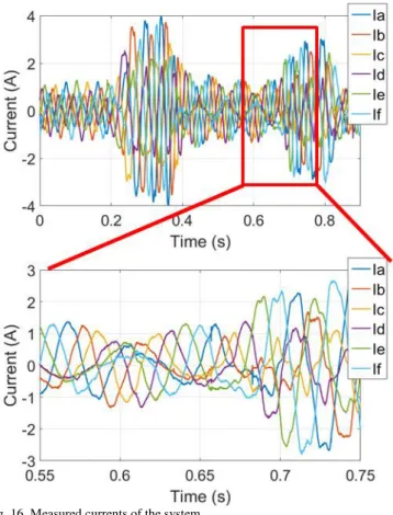
Fig. 16. Measured currents of the system.
generated by the control for each machine. Because of the series-connection, the same currents flow in both machines. Then, these current references sum up yielding to irregular waveforms, as presented in Fig. 16.
The Back-EMF of each machine (Fig. 17) is related to each fundamental frequency. As each machine turns in a different speed, the frequencies of the Back-EMF are different. Then the currents being the same for both machines have a component for each frequency. When analyzing the Back-EMF and the currents in the αβ references, the relation between of the current components of the fictitious machines αβ1 and the Back-EMF of the machine M1 in the αβ references are simple. They have the same frequency and they are in phase. Besides the amplitude variation due to speed variation, the same relation can be obtained by comparing the current components of the fictitious machines αβ2 and the Back-EMF of the machine 2 in the αβ references. However this relation is not visible in the measured currents.
VI. CONCLUSION
The method proposed in this paper extends the existing method to even-phase machines whose number of phases is not divisible by four. The two most important achievements of this method are the possibility of connecting two identical symmetrical 6-phase PMSM and the fact of highly reducing constraints on the rotor dimensioning of a PMSM in order to decouple the control of the machines.
Fig. 17. Measured Current and estimated Back-EMF of phase A (top), of fictitious machines αβ1 (middle) and αβ2 (bottom).
With the proposed method it is possible to use almost classical three-phase machines with just a modification of their internal connections in order to output three supplementary connections to obtain what is called a six-phase symmetrical machine. Besides, all the machines series-connected can be identically dimensioned, different from a 6-phase machine connected to 3-phase one.
Most of PMSM in the industry have no even Back-EMF harmonics thanks to the rotor symmetry. This condition is enough to ensure that the control of the series-connected machines is decoupled, without need of implementing a supplementary control strategy or specific dimensioning the rotor.
Using the proposed methodology, the classical benefits of series-connections such as the reduction by two of the transistors [21] are not reserved anymore to multi-phase machines with special design.
REFERENCES
[1] M. J. Duran and F. Barrero, “Recent Advances in the Design, Modeling, and Control of Multiphase Machines - Part II,” IEEE Transactions on
Industrial Electronics, vol. 63, no. 1, pp. 459–468, Jan. 2016.
[2] Mohammadpour, A. Gandhi, and L. Parsa, “Design and control of fault-tolerant permanent magnet machines,” IEEE Workshop on Electrical
Machines Design Control and Diagnosis (WEMDCD), pp. 108–116,
Mar. 2013.
[3] X. Roboam, B. Sareni, and A. Andrade, “More Electricity in the Air: Toward Optimized Electrical Networks Embedded in More-Electrical Aircraft,” IEEE Industrial Electronics Magazine, vol. 6, no. 4, pp. 6–17, Dec. 2012.
[4] P. Wheeler and S. Bozhko, “The More Electric Aircraft: Technology and challenges,” IEEE Electrification Magazine, vol. 2, no. 4, pp. 6–12, Dec. 2014.
[5] J. A. Rosero, J. A. Ortega, E. Aldabas, and L. Romeral, “Moving towards a more electric aircraft,” IEEE Aerospace and Electronic
Systems Magazine, vol. 22, no. 3, pp. 3–9, Mar. 2007.
[6] Wenping Cao, B. C. Mecrow, G. J. Atkinson, J. W. Bennett, and D. J. Atkinson, “Overview of Electric Motor Technologies Used for More Electric Aircraft (MEA),” IEEE Transactions on Industrial Electronics, vol. 59, no. 9, pp. 3523–3531, Sep. 2012.
[7] T. J. dos Santos Moraes, N. K. Nguyen, F. Meinguet, and E. Semail, “Fault tolerant dual-motor drives: Sizing of power electronic,” European
Conference on Power Electronics and Applications (EPE'15 ECCE-Europe), 2015, pp. 1–10.
[8] T. J. dos Santos Moraes, N. K. Nguyen, E. Semail, F. Meinguet, and M. Guerin, “Dual-Multiphase Motor Drives for Fault-Tolerant Applications: Power Electronic Structures and Control Strategies,” IEEE Transactions
on Power Electronics, pp. 1–1, Feb. 2017.
[9] M.-A. Shamsi-Nejad, B. Nahid-Mobarakeh, S. Pierfederici, and F. Meibody-Tabar, “Control strategies for fault tolerant PM drives using series architecture,” IEEE Vehicule Power and Propulsion Conference
(VPPC’10), 2010, pp. 1–6.
[10] S. Gataric, “A polyphase cartesian vector approach to control of polyphase AC machines,” Industry Applications Conference, 2000, vol. 3, pp. 1648–1654.
[11] E. Levi, A. Iqbal, S. N. Vukosavic, and H. A. Toliyat, “Modeling and control of a five-phase series-connected two-motor drive,” Conference
on IEEE Industrial Electronics Society (IECON’03), 2003, pp. 208–213.
[12] E. Semail, X. Kestelyn, and A. Bouscayrol, “Right harmonic spectrum for the back-electromotive force of an n-phase synchronous motor,”
Industry Applications Conference, IAS Annual Meeting , vol. 1, pp. 71–
78., Oct. 2004.
[13] M. Jones, E. Levi, and A. Iqbal, “A five-phase series-connected two-motor drive with current control in the rotating frame,” Power
Electronics Specialists Conference (PESC’04), 2004, pp. 3278–3284.
[14] E. Levi, M. Jones, S. N. Vukosavic, and H. A. Toliyat, “A Novel Concept of a Multiphase, Multimotor Vector Controlled Drive System Supplied From a Single Voltage Source Inverter,” IEEE Transactions on
Power Electronics, vol. 19, no. 2, pp. 320–335, Mar. 2004.
[15] A. Iqbal, S. Vukosavic, E. Levi, M. Jones, and H. A. Toliyat, “Dynamics of a series-connected two-motor five-phase drive system with a single-inverter supply,” Industrial Applications Conference (IAS’05), 2005, vol. 2, pp. 1081–1088.
[16] E. Levi, M. Jones, S. N. Vukosavic, A. Iqbal, and H. A. Toliyat, “Modeling, Control, and Experimental Investigation of a Five-Phase Series-Connected Two-Motor Drive With Single Inverter Supply,” IEEE
Transactions on Industrial Electronics, vol. 54, no. 3, pp. 1504–1516,
Jun. 2007.
[17] E. Semail, E. Levi, A. Bouscayrol, and X. Kestelyn, “Multi-machine modelling of two series connected 5-phase synchronous machines: effect of harmonics on control,” European Conference on Power Electronics
and Applications (EPE'15 ECCE-Europe), 2005, pp. P.1- P.10.
[18] H.-C. Chen, C.-H. Hsu, and D.-K. Chang, “Speed control for two series-connected five-phase permanent-magnet synchronous motors without
position sensor,” IEEE International Symposium on Industrial
Electronics (ISIE’16), 2016, pp. 198–203.
[19] M. Mengoni, A. Tani, L. Zarri, G. Serra, and D. Casadei, “Position Control of a Multi-Motor Drive Based on Series-Connected Five-Phase Tubular PM Actuators,” IEEE Transactions on Industry Applications, vol. 48, no. 6, pp. 2048–2058, Nov. 2012.
[20] F. Mekri, J.-F. Charpentier, and E. Semail, “An efficient control of a series connected two-synchronous motor 5-phase with non-sinusoidal EMF supplied by a single 5-leg VSI: Experimental and theoretical investigations,” Electric Power Systems Research, vol. 92, pp. 11–19, Nov. 2012.
[21] E. Levi, M. Jones, and S. N. Vukosavic, “Even-phase multi-motor vector controlled drive with single inverter supply and series connection of stator windings,” IEE Proceedings - Electric Power Applications, vol. 150, no. 5, p. 580, Sep. 2003.
[22] E. Levi, R. Bojoi, F. Profumo, H. A. Toliyat, and S. Williamson, “Multiphase induction motor drives – a technology status review,” IET
Electric Power Applications, vol. 1, no. 4, p. 489, 2007.
[23] M. Jones, S. N. Vukosavic, and E. Levi, “Experimental performance evaluation of six-phase series-connected two-motor drive systems,”
European Conference on Power Electronics, 2005, p. 12 pp.-pp.P.12.
[24] M. Jones, S. N. Vukosavic, E. Levi, and A. Iqbal, “A Six-Phase Series-Connected Two-Motor Drive With Decoupled Dynamic Control,” IEEE
Trans. Ind. Appl., vol. 41, no. 4, pp. 1056–1066, Jul. 2005.
[25] E. Levi, M. Jones, S. Vukosavic, and H. Toliyat, “Steady State Modeling of Series-Connected Five-Phase and Six-Phase Two-Motor Drives,”
IEEE Trans. Ind. Appl., vol. 44, no. 5, pp. 1559–1568, Sep. 2008.
[26] M. Saleh, A. Iqbal, S. M. Ahmed, H. Abu Rub, and A. Kalam, “Carrier based PWM technique for a three-to-six phase matrix converter for supplying six-phase two-motor drives,” Conference on IEEE Industrial
Electronics Society (IECON’11), 2011, pp. 3470–3475.
[27] J. Malvar et al., “Graphical Diagram for Subspace and Sequence Identification of Time Harmonics in Symmetricalal Multiphase Machines,” IEEE Transactions on Industrial Electronics, vol. 61, no. 1, pp. 29–42, Jan. 2014.
[28] Xiao Zhicai, Wang Jing, Liu Huasong, Han Haopeng, and Liu Lingshun, “Active disturbance rejection control strategy for symmetrical six-phase and three-phase PMSM two-motor series-connected system,” IEEE
International Conference on Electronic Measurement & Instruments (ICEMI’15), 2015, pp. 1354–1358.
[29] E. Levi, S. N. Vukosavic, and M. Jones, “Vector control schemes for series-connected six-phase two-motor drive systems,” IEE Proceedings -
Electric Power Applications, vol. 152, no. 2, p. 226, 2005.
[30] R. Michel, M. Bekemans, M. Guillaume, E. Semail, “Device for controlling two multiphase motors”, European Patent 2903155 , August 05, 2015.
[31] F. Locment, E. Semail, and X. Kestelyn, “Vectorial Approach-Based Control of a Seven-Phase Axial Flux Machine Designed for Fault Operation,” IEEE Transactions on Industrial Electronics, vol. 55, no. 10, pp. 3682–3691, Oct. 2008.