Science Arts & Métiers (SAM)
is an open access repository that collects the work of Arts et Métiers Institute of Technology researchers and makes it freely available over the web where possible.
This is an author-deposited version published in: https://sam.ensam.eu Handle ID: .http://hdl.handle.net/10985/9154
To cite this version :
Bassel ASLAN, Eric SEMAIL - New 5-Phase Concentrated Winding Machine with Bi-Harmonic Rotor for Automotive Application - In: IEEE- ICEM International Congress on Electrical Machines, Germany, 2014-09 - New 5-Phase Concentrated Winding Machine with Bi-Harmonic Rotor for Automotive Application - 2014
Any correspondence concerning this service should be sent to the repository Administrator : [email protected]
1
ΦAbstract -- For a power range from 10 to 30 kW, 5-phase
machines are well adapted to low-voltage (48V) supply thanks to their reduced current per phase. For three-phase machines but with higher voltages (>120V), machines with a number of slots per pole and per phase spp equal to 0.5 (as the
12slots/8poles combination) are widely used in hybrid automotive applications when a wide speed range is required. The reason is that the value of spp=0.5 guarantees no
sub-harmonics and thus induces low level of permanent magnet rotor losses. In this paper a 20slots/8poles/5phases machine is chosen. With a winding factor of only 0.588 for the first harmonic, this machine is only interesting if its high third harmonic winding factor (0.951) is used. Thus, a new bi-harmonic rotor structure is presented. Thanks to adequate control with flux-weakening and ratio r between first and third harmonic currents, the maximum torque versus speed characteristic is determined.
Index Terms-- Traction, Multi-Phase, 5-phase,
Concentrated Winding, Rotor Losses, Automotive, MMF
I. INTRODUCTION
NTERIOR Permanent Magnet motors (IPM) with fractional-slot concentrated winding are becoming an interesting choice for automotive application, due to their high torque/volume ratio, high efficiency, and simple structure which means easy manufacturing, maintenance, and recycling [1]. The problem with machines of fractional-slot concentrated winding is the existence of parasitic effects which can be unbearable, like unbalanced mechanical structure or high eddy-currents rotor losses at high speeds especially in Permanent Magnets. Therefore, many researches tried to classify this type of machines in order to avoid bad choice of Slots/Poles combination which leads to undesired parasitic effects [2]-[3].
Multiphase drives have several general advantages of high value in automotive applications, such as more efficient fault tolerant capacity in comparison with 3-phase drives [4]-[5]. Lower current per phase is also one of appreciated qualities in multi-phase drives especially when low DC Bus voltage (as 48V) is used to benefit from low-cost security norms for the supply. In this case, the fact of having lower current per phase decreases the constraints and cost on the power electronic devices. The reason is that it is then no more necessary, in order to bear the total current, to use k transistors working in parallel. As consequence, the oversizing which is necessary for preventing from the failure of one of the k transistors can be avoided.
Historically, interior permanent magnet machines with distributed windings are often chosen for electrical and
E. Semail is with the Laboratory of Electrical Engineering and Power Electronics of Lille L2ep at Arts et Metiers Paristech, Lille, 8 Bd Louis XIV 59043 France ([email protected])
B. Aslan is with L2EP and Valeo, Créteil, 2 rue André Boulle 94000 France ( e-mail1: [email protected]),
hybrid automotive propulsion systems thanks to their capacity to reach required high speeds with constant power [8]. One of the reasons behind that is high reluctant torque at low speeds which allows getting a powerful machine without the necessity of high magnet flux. Consequently, efficient flux weakening procedure can be applied allowing constant power functionality at high speeds. On the contrary, machines with tooth concentrated winding cannot always provide high reluctant torque because of their fractional winding type. Thus torque-speed characteristics with wide constant power speed range are difficult to obtain.
The aim of the paper is to propose a low-voltage machine with teeth concentrated winding and whose wide constant power speed range is obtained by using the ability of a 5-phase machine to produce torque with the first and the third harmonic of current [7]-[3].
The 5-phase machine proposed in this paper has a 20slots/8poles combination with spp=0.5 which guarantees
low rotor losses at high speeds. On the other hand, for producing the high torque necessary for boost effect in hybrid automotive application, this machine suffers from a low fundamental winding factor (0.588) which implies too high currents in the power devices if only the first harmonic is used. Fortunately a high third-harmonic winding factor (0.951) allows by injection of a third harmonic current to obtain high torque with classical current densities.
However, in order to make benefits of the corresponding property of high third-harmonic winding factor, it is also necessary to define a new rotor pattern since the classical ones do not provide a flux density distribution with a satisfying third harmonic in the air gap [9]-[10] . The paper proposes thus a new bi-harmonic rotor configuration allowing the combination 20slots/8poles to provide thus an interesting torque at low speeds and wide speed range functionality with constant power.
The paper is divided into four sections. The first section begins with a theoretical analysis about the machine winding configuration. First and third harmonic winding factors are calculated. Then, an original bi-harmonic rotor design that makes profit of the 5-phase stator structure is presented. This design allows, thanks to a third harmonic current injection, a boost torque effect at low speeds.
The two next sections allow to define a drive with a torque versus speed characteristic and an efficient wide constant power speed range: in low speed region (section 3) copper losses are considered for determining the optimized ratio between the first and third harmonic currents whereas in high speed region (section 4) only the first harmonic is used in order to minimize eddy current losses in the permanent magnets.
The last section explains by a spectrum analysis of the Magnetomotive Force (MMF) why, with the proposed concentrated winding, much higher PM rotor losses are observed in Finite Element Models when a third harmonic current is injected.
New 5-Phase Concentrated Winding Machine with
Bi-Harmonic Rotor for Automotive Application
B. Aslan, E. Semail
2 II. WINDING FACTORS CALCULATION AND A NEW ROTOR
STRUCTURE
Winding factors of fundamental and third harmonic
) ,
(k1 k3 are calculated using the method of voltage phasor diagram presented in [9]. This method represents the machine slot coils as vectors in the electrical plane. The mechanical angle between two slots ϕ becomes in the slot electrical plane associated with the first harmonic:
slot
p×ϕ with p: number of pairs of poles.
While in the electrical plane associated with the third harmonic it will be:
slot
p×ϕ × 3
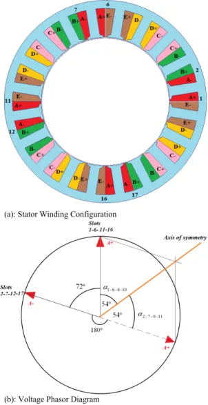
Fig. 1 (a) shows the concentrated winding topology of the combination 20slots/8poles with double layer and Fig.1 (b) shows the voltage phasor diagram of one of the phases in the machine.
Let us consider the general formulation of winding factor corresponding to different harmonics ν [9]:
∑
= = Z Z k 1 ) cos( 2 . sin ρ ρ ν α π ν (1)Z: number of phasors in each phase :
ρ
α phasor angle according to the axis of symmetry By applying equation (1) on the voltage phasor diagram in Fig.1 (b), winding factors (k1,k3) can be calculated:
951 . 0 )) 54 3 cos( 8 ( 8 1 588 . 0 )) 54 cos( 8 ( 8 1 3 1 ≈ × × − = ≈ × = o o k k
It can be noticed from previous calculation that the fundamental winding factor k1 is relatively low in
comparison with 0.866 for 12slots/8poles/3-phases configuration of the same spp. This means that, the
fundamental harmonic of back-EMF (back-ElectroMotive Force) will be too weak to get an efficient powerful machine with a minimum acceptable torque.
However, since the five-phase structure allows the third back-EMF harmonic to generate a constant torque [7]-[4], the high third harmonic winding factor k3 of the
combination 20slots/8poles can be exploited. In addition to this good winding factor (k3), a higher third harmonic of
magnetic field density in the air gap is essential for ensuring an exploitable level of the 3rd back-EMF
harmonic.
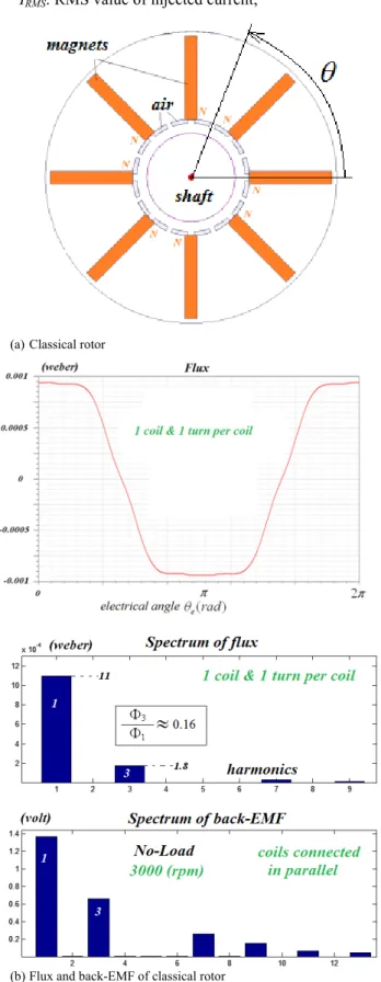
Generally, classical Permanent Magnet rotor configurations provide a trapezoidal flux density distribution in the air gap inducing, with integer slot windings, also trapezoidal emf. As a result, the third harmonic of this distribution cannot exceed 33 % of the fundamental one [9]. Therefore, this paper proposes a new IPM rotor pattern, adapted for the combination 20slots/8poles, which enhances the 3rd harmonic of rotor
flux density. The principle is to add 16 small radial magnets in addition to the 8 original big ones. Fig. 2 (a) and Fig. 3
(a) show both classical and new rotor structure. Finite elements (FE) models are built with "Maxwell/ANSYS" software for the combination 20slots/8poles with both rotors. The results of no-load calculation are illustrated in Fig. 2 (b) and Fig. 3 (b). In this figure, flux and back-EMF are calculated for the same stator and winding topology presented in Fig. 1 (a). It must be remarked that with classical integer slot windings such results should be quite difficult to obtain.
By observing the flux spectrums it can be noticed that the bi-harmonic rotor pattern redistributes the flux between the fundamental and the 3rd harmonic. As a result, the
back-EMF 3rd harmonic of the new structure is widely increased.
The impact of this modification on the machine performance is investigated in the next paragraphs.
(a): Stator Winding Configuration
(b): Voltage Phasor Diagram
Fig.1 Stator with double layer concentrated winding topology of the combination 5-phase 20 slots/8 poles
III. TORQUE AT LOW SPEEDS
In a 5-phase machine, both first and third current harmonic are able to produce a constant torque [12].
By injecting first and third current harmonic, the constant electromagnetic torque (T) produced by the machine can be written:
3 2 ) ( ) . 3 . ( 2 5 2 3 2 1 3 3 1 1 I I I I I p T RMS = + Φ × + Φ × × = (2)
(I1, I3): peak value of first and third current harmonic;
(Ф1, Ф3): peak value of first and third flux harmonic;
IRMS: RMS value of injected current;
(a) Classical rotor
(b) Flux and back-EMF of classical rotor
Fig. 2 Combination 5-phase 20 slots/8 poles with a classical rotor structure
(a) Bi-harmonic rotor
(b) Flux and back-EMF of bi-harmonic rotor
Fig. 3 New bi-harmonic rotor structure developed to improve the performance of the combination 5-phase 20 slots/8 poles
For a given RMS value of applied current the distribution between the fundamental and 3rd harmonic can be
considered and expressed with a coefficient (r). The optimal distribution (r) which allows maximizing the ratio
RMS
I
T can be deduced by solving the equation dT/dr (r)= 0 :
4 2 3 1 3 1 2 3 1 3 1 3 1 0 : 1 2 2 ⎟⎟ ⎠ ⎞ ⎜⎜ ⎝ ⎛ Φ × Φ + Φ × Φ = < < × − × = × × = optimal RMS RMS r r I r I I r I (3)
The final resulting optimal torque (Toptimal) thanks to this
optimal current harmonics exploitation is calculated: 2 3 2 1 9 ( 2 2 5⋅ ⋅ ⋅ ⋅ Φ + ⋅Φ = RMS optimal p I T (4)
The new rotor structure presented in Fig. 3 (a) is designed in a way which maximizes the final torque resulting from the optimal current harmonics distribution (3). In other words, the bi-harmonic rotor rearranges the flux harmonics in order to better exploit the machine using current harmonics control.
Using equation (4) and the FE results in the figures 2-3, the torque enhancement obtained with the new bi-harmonic rotor structure can be deduced:
35 . 1 ) ( ) ( = rotor classical optimal rotor new optimal T T
So, the combination 20slots/8poles/5phases is able to produce 35% more torque with the same volume of rotor by using the proposed rotor pattern. This fact allows the presented 20slots/8poles combination to find a place among the interesting machines for automotive wide-speed applications which must be supplied with a low voltage DC bus.
Moreover, the machine torque is also calculated using the finite elements models in both rotor cases. The machine specifications used in FE torque calculation are represented in Table 1.
Table 1
Main specifications of the machine for FE calculation
Stator diameter 144 mm
Rotor diameter 89,8 mm
Length 91.7 mm
Injected Current harmonics 1st & 3rd
Surface current density 6 A/mm2
The results are illustrated versus time in Fig. 4. FE calculations are done at the same IRMS value but with 3
different harmonic distributions. The torque enhancement at the same RMS current is, according to FEM results given in Fig. 4, about:
% 35 2 . 19 2 . 19 26 ) ( ) ( ) ( = − = − rotor classical rotor classical rotor new T T T
Since the reluctant torque is negligible in the studied structure, the last result corresponds to this one found analytically thanks to formulas (2) and (4), confirming thus the interest of the new proposed rotor.
From the other hand, it can be noticed in Fig. 4 (b) that the torque generated by the third current harmonic is much
more higher than this one produced by the fundamental current. This fact is related to the drop in the fundamental flux harmonic due to the new structure leading to lower fundamental torque. Thanks to this last feature, a wide flux weakening region can be obtained as it is shown in the next paragraph.
IV. FLUX WEAKENING OPERATION
In order to define and examine the flux weakening characteristics of the combination 5-phase 20slots/8poles provided with the new rotor structure, machine parameters are calculated using its finite element model. This calculation contains the inductances and magnets flux which corresponds to the two independent planes: (id1 q,i1)
for the fundamental harmonic and (id2 q,i 2) for the third harmonic [13]-[14].
(a) Torques with the classical rotor
(b) Torques with the new bi-harmonic rotor configuration
(c) New bi-harmonic rotor FE flux density cartography Fig. 4 FE dynamic torque calculation at 3000 (rpm) for the combination 20slots/8poles/5phases with two rotor structures and a constant RMS current density (6A/mm2)
5 Using these parameters with a proper flux weakening strategy, the characteristics of torque and powers versus speed are calculated and illustrated in Fig. 5. A repartition control of the harmonics is applied aiming to improve the machine performance. Two main functionality regions can be detected in this harmonic control (see Fig. 5):
• Low speed region where the RMS current is distributed between fundamental and third harmonic basing on the optimal exploitation of equation (3). Consequently, the ratio T IRMS is maximized and a sufficient torque is generated as it can be noticed in Fig. 5 (a);
• High speed region where the RMS current is injected only as a fundamental harmonic. In this region the impact of the new rotor structure on flux spectral repartition becomes of high value. The reason is that the fundamental harmonic of magnets flux is already weakened (-43%) thanks to the new bi-harmonic rotor (see Fig. 2 (b) and Fig. 3 (b)). Consequently, lower current density in the machine slots is needed in order to keep constant power functionality as it is shown in Table 2. The transition speed (5000 rpm) between the low and high region has been defined in order to obtain a continuous speed range with constant power (Fig4.b). This transition speed can be modified by adequate modification of the ratio between the first and third flux harmonic.
Table 2
High speed-constant power functionality comparison between classical and bi-harmonic rotor
Machine with: classical rotor Bi-harmonic rotor Current harmonics fundamental fundamental Surface current density 21.4 A/mm2 11.5 A/mm2
Mechanical output
power 10 kW 10 kW
V. EDDY-CURRENT ROTOR LOSSES
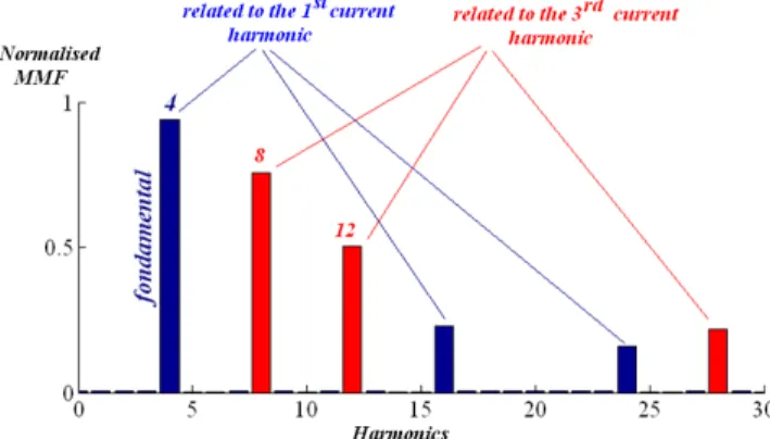
One of the reasons behind rotor losses in synchronous machines is the MMF parasitic harmonics which are asynchronous with the rotor. Moreover, the MMF spatial spectrum (in the air gap) of the machines provided with concentrated windings around teeth contains generally more parasitic harmonics [15]-[16] than machine with integer slot distributed windings. These additional harmful harmonics are classified basically into sub-harmonics (with an order lower than fundamental) and harmonics close to fundamental [6].
The 5-phase machine studied in this paper belongs to a certain family of combinations with a very low level of eddy-current rotor magnets losses [6]. This quality is related to its MMF spatial spectrum which is clean from harmful harmonics (sub-harmonics or close to fundamental ones), if only the fundamental current is applied (see Fig. 6).
However, when the 3rd current harmonic is injected a
new harmful MMF harmonic appears. Fig. 6 shows this new parasitic harmonic which has a spatial frequency equal to 8.
The harmonic with a spatial frequency equal to 12 is synchronous with the rotor, which makes this harmonic equivalent to the fundamental in a 5-phase structure. Unlike
the 12th harmonic, the 8th one is asynchronous with the
rotor which causes high level of magnets losses. As a result, important values of third current harmonic cannot be injected at high speeds: high temperatures could be reached in the rotor magnets leading to their demagnetization.
(a) Torque-Speed characteristics
(b) Power-Speed characteristics
Fig. 5 Characteristics of the 5-phase 20slots/8poles machine with the bi-harmonic rotor structure and adequate flux weakening control with repartition of current harmonics and global 11,5 A/mm2 RMS current density
Fig. 6 MMF spatial spectrum in the air gap for the combination 5-phase 20slots/8poles supplied with two current harmonics
Besides, applying a 3rd current harmonic with high
frequency (at high speed) will add considerable constraints on power electronics drive (more switching losses). For this reason and since magnet losses depend roughly on the square of the speed, it has been chosen to inject the 3rd
6 VI. CONCLUSION
In this paper a 5-phase teeth concentrated winding machine (20 slots/8 poles) adapted to low voltage DC bus in the range of 10-30 kW has been proposed. When supplied by the first harmonic of current this combination whose spp is equal to 0.5, presents an interesting spectrum
of MMF which guarantees low rotor losses even at the high speeds and frequencies required by automotive applications.
Suffering from a low first harmonic winding factor but benefiting of a high third harmonic winding factor, the 20 slots/8 poles combination is promoted thanks to a special bi-harmonic rotor structure which allows to produce high torque values with reasonable current densities. Short duration boost torque required by automotive applications can thus be provided especially in low speed region.
Finally the torque-speed and power-speed characteristics obtained thanks to an adequate flux weakening control and repartition between first and third harmonic current is provided thanks to a Finite Element Software.
VII. ACKNOWLEDGMENT
Acknowledgment for ADEME funding for MHYGALE project
VIII. REFERENCES
[1] A.M El-Refaie, "Fractional-Slot Concentrated-Windings Synchronous Permanent Magnet Machines: Opportunities and Challenges", IEEE Trans. on Industrial Electronics, Vol. 57, No. 1, January 2010..
[2] F. Magnussen, H. Lendenmann, "Parasitic Effects in PM Machines with Concentrated Windings," IEEE Trans. on Industry Applications, vol.43, no.5, pp.1223-1232, Sept-Oct. 2007.
[3] B. Aslan, E.Semail, J. Legranger, "Slot/pole Combinations Choice for Concentrated Multiphase Machines dedicated to Mild-Hybrid Applications", in Proc. 2011 IEEE Industrial Electronics Congress, pp 3698 - 3703 .
[4] L. Parsa, H.A. Toliyat, "Fault-Tolerant Interior-Permanent-Magnet Machines for Hybrid Electric Vehicle Applications," IEEE Transactions on Vehicular Technology, vol.56, no.4, pp.1546,1552, July 2007.
[5] J. Figueroa, J. Cros, P. Viarouge, "Polyphase PM brushless DC motor for high reliability application", in Proc. 2003 European Power
Electronics Congress
[6] B. Aslan, E. Semail, J. Legranger, "General Analytical Model of Magnet Average Eddy-Current Volume Losses for Comparison of Multiphase PM Machines With Concentrated Winding", IEEE Trans. on Energy Conversion, vol.29, no.1, pp.72,83, March 2014.
[7] E. Levi, “Multiphase electric machines for variable-speed applications,” IEEE Trans. on Industrial Electronics, vol. 55, no. 5,
2008, pp. 1893-1909.
[8] I. Boldea, L.N. Tutelea, L. Parsa, D. Dorrell, "Automotive Electric Propulsion Systems With Reduced or No Permanent Magnets: An Overview," IEEE Trans. on Industrial Electronics, vol.61, no.10, pp.5696-5711, Oct. 2014
[9] L. Parsa, Namhun Kim, H.A. Toliyat, "Field Weakening Operation of High Torque Density Five-Phase Permanent Magnet Motor Drives," in Proc. 2005 IEEE Electric Machines and Drives Conf. pp.1507-1512.
[10] L. Parsa, H.A. Toliyat, "Five-phase permanent-magnet motor drives," IEEE Trans. on Industry Application , vol.41, no.1, pp.30,37, Jan.-Feb. 2005
[11] J. Pyrhonen, T. Jokinen, V. Hrabovcova, "Design of rotating electrical machines", 1st edition, Wiley, Book, pp.63-66, 2008. [12] F. Scuiller, J.-F. Charpentier, E. Semail, S. Clenet, "Comparison of
two 5-phase Permanent Magnet machine winding configurations. Application on naval propulsion specifications" In Proc.2007 IEEE
Electric Machines & Drives Conference, pp.34-39.
[13] E. Semail, A. Bouscayrol, J.P. Hautier, "Vectorial formalism for analysis and design of polyphase synchronous machines", EPJ AP (European Physical Journal-Applied Physics), Vol 22, N°3, pp. 207-220, 2003.
[14] E. Semail, X. Kestelyn, A. Bouscayrol, "Right Harmonic Spectrum for the back-electromotive force of a n-phase synchronous motor", in Proc 2004, IEEE Industrial Application Society Annual Meeting.. [15] N. Bianchi, E. Fornasiero, "Impact of MMF Space Harmonic on
Rotor Losses in Fractional-Slot Permanent-Magnet Machines", IEEE Trans. on Energy Conversion, vol.24, no.2, pp.323-328, June 2009. [16] A.M. El-Refaie, M.R. Shah, Ronghai Qu, J.M. Kern, "Effect of
Number of Phases on Losses in Conducting Sleeves of Surface PM Machine Rotors Equipped With Fractional-Slot Concentrated Windings," IEEE Trans. on Industry Applications, vol.44, no.5, pp.1522-1532, sept.-oct. 2008.
IX. BIOGRAPHIES
Bassel Aslan (S’10–M’12) received the M.S. degree in electrical
engineering from the Ecole Normale Supérieure de Cachan, University Paris 11, Paris, France, in 2009, and the Ph.D. degree in electrical engineering from the Laboratory of Electrical Engineering and Power Electronics of Lille (L2EP), Arts et Métiers ParisTech, Lille, France, in 2013. Since 2010, he has been with Valeo, Créteil,
France, where he is involved in the topics of electrical machines for automotive applications. His current research interests include the design of multiphase machines with concentrated winding, including control and power electronics.
Eric Semail (M’02) received the M.S. degree from Ecole Normale
Supérieure, Paris, France, in 1986, and the Ph.D. degree, with specializations in tools and the method of polyphase electrical systems and generalization of the space vector theory, from Lille University, Lille, France, in 2000. He is currently with the Laboratory of Electrical Engineering and Power Electronics of Lille (L2EP), Campus Arts et Métiers ParisTech, where he became an Associate Professor in 2001 and a Full Professor in 2010. His current research interests include the design, modeling, and control of multiphase drives (converters and ac drives). He is involved in studying multimachine and multiconverter systems and in automotive,marine, and off-shore wind power.
. .