To link to this article: DOI: :
10.1016/j.ijrmhm.2015.12.009
: http://dx.doi.org/10.1016/j.ijrmhm.2015.12.009
This is an author-deposited version published in:
http://oatao.univ-toulouse.fr/
Eprints ID: 14647
To cite this version:
Yahiaoui, Malik and Paris, Jean-Yves and Delbé, Karl and Denape, Jean
and Gerbaud, Laurent and Colin, Christophe and Ther, Olivier and
Dourfaye, Alfazazi Quality and wear behavior of graded polycrystalline
diamond compact cutters. (2016) International Journal of Refractory
Metals and Hard Materials, vol. 56. pp. 87-95. ISSN 02634368
O
pen
A
rchive
T
oulouse
A
rchive
O
uverte (
OATAO
)
OATAO is an open access repository that collects the work of Toulouse researchers and
makes it freely available over the web where possible.
Any correspondence concerning this service should be sent to the repository
administrator:
[email protected]
Quality and wear behavior of graded polycrystalline diamond
compact cutters
M. Yahiaoui
a,⁎
, J.-Y. Paris
a, K. Delbé
a, J. Denape
a, L. Gerbaud
b, C. Colin
c, O. Ther
c, A. Dourfaye
daUniversité de Toulouse, Laboratoire Génie de Production, France bMines ParisTech, Centre de Géosciences, France
cMines ParisTech, Centre des Matériaux, France dVarel Europe, France
a b s t r a c t
The wear behavior of conventional and graded polycrystalline diamond compact cutters was studied using a ver-tical lathe with mortar counterfaces. Different cutters were considered regarding to their diamond grain size and the high pressure and the high temperature conditions of the manufacturing process (HPHT). On the base of these cutters, a cobalt graduation process was performed on the WC–Co substrates by reactive imbibition. A quality factor developed in previous studies was calculated to evaluate cutters wear performances. The results showed that a controlled HPHT process can act on the wear resistance certainly by improving the diamond grain boundary cohesion. Unexpectedly, the diamond granulometry appeared to be a secondary factor influenc-ing the wear resistance. The reactive imbibition clearly increased the wear resistance, even for cutters with coarse diamond grains (i.e. potentially impact resistant). Finally, a third body approach describes that the quartz parti-cles detached from the mortar rock realizes abrasive scratches on the cutters wear flat. When the wear flat reaches the substrate, the formation of voids in the contact, associated with the trapping of abrasive particles, rises the wear kinetic. As a secondary mechanism, Raman spectroscopy measurements highlighted tribological transformed structures by the formation of graphite and amorphous carbon on the diamond worn surfaces.
Keywords: Diamond Tungsten carbide–cobalt Reactive imbibition Wear testing Third body Graphite 1. Introduction
Two main families of tools are employed in the drilling industry: roller cone with WC–Co inserts and polycrystalline diamond compact (PDC) bits formed by PDC/WC–Co cutters. First studies showed that the PDC bits should be used at lower load than the roller cone bits[1]. That is why the PDC bits operate in soft rock to medium hard formations essentially by shear mode. In harder fields, roller cone bits are rather used in performing impact excavations. Nevertheless, the drag bits could drill twice faster and longer than roller bits even in hard formations[2]. Accordingly, the market share of PDC cutters toward roller cone inserts reached 50% in 2002 and is estimated at 80%in 2020
[3].
The earth's crust is composed by 80% of hard and potentially abrasive material (e.g. alumina, silica, hematite). This explains that the PDC bits suffer mainly from abrasive wear[4]. The abrasive wear is de-scribed in the literature by microcuttings of diamond grains by abrasive grains coming from the rock in the contact[5]. At the PDC microstruc-ture level, the wear mechanisms are exposed as intergranular and
transgranular cracks and cobalt phase depletion leading to diamond grain pullouts[6].
In severe conditions (e.g. in hard rocks with high applied load), the PDC bits are also subjects to impact damages and thermal wear. When the temperature is over 600 °C in the air, the thermal wear is produced by oxidation (i.e. combustion)[7]. However, during excavation experi-ments, Glowka[8]showed that the wear rate of PDC cutters increases when the contact temperature reaches 350 °C. This author assumed that this phenomenon is associated to the graphitization or the amorphization of the metastable PDC microstructure. These physico-chemical transformations of the contact surfaces are also called tribological transformed structures (TTS) [9] and are induced by mechanical and/or thermal condition in the contact.
In practice, one recurrent aim of the manufacturers is to improve the PDC cutters wear resistance without affecting their ability to undergo repetitive impacts in harder formations. In this way, graduation pro-cesses were developed to increase the impact resistance of the cutters body without affecting the abrasive resistance of the active surface in contact with the rock. This study focuses on PDC cutters made by the imbibition process first introduced by Lisovsky[10]. As presented by Lefort-Sorlier et al.[11], this process consists on a gradual enrichment of cobalt in the WC–Co substrate. These authors associated to the imbi-bition process a boron nitride reactive coating on the substrates forming
⁎ Corresponding author at: Ecole Nationale d'Ingénieurs de Tarbes, 47 avenue d'Azereix, 65016 Tarbes, France.
borides WCoB at the PDC/WC–Co interface[12,13]. The borides forma-tion should enhance the PDC mechanical resistance.
Actually, few studies focused on the wear resistance of innovative graded PDC cutters. In previous studies, a quality factor Q was devel-oped to better characterize the wear resistance of PDC cutters[14]. After wear experiments, this factor considers not only the wear rate of PDC cutters but also the cutting efficiency of these cutters. In other words, this factor gives information of wear resistance with regards to the forces applied on it during experiments (i.e. friction and cutting forces). The aim of this work is then to evaluate the quality of cutters treated by reactive imbibition and to suggest wear mechanisms associ-ated to the quality results.
Nomenclature
α Back rake angle, deg; ΔHWC Hardness range, HV 2 kg/10 s;
ε Intrinsic specific energy, J⋅m-3;
η Cutting efficiency;
μ Friction coefficient;
DPDC Mean diamond grain size, m;
DWC Mean WC grain size, m;
Ac Cross-sectional area of cut, m2;
Af Wear flat area, m2;
FN Total normal force, N;
FNf Normal friction force component, N;
FT Total drag force, N;
FT0 Initial transverse force, N;
HWC Substrate mean hardness, HV 2 kg/10 s;
k Wear rate, m3
⋅ N‐1⋅ m‐1; L Excavation distance, m; LT Total excavation distance, m;
pCoPDC PDC cobalt content, wt.%;
pCoWC Substrate cobalt content, wt.%;
Q Quality factor; Qi, Internal flow, m3⋅ s‐1;
Qr, Recycling flow, m3⋅ s‐1; Qs, Source flow, m3⋅ s−1; Qw, Wear flow, m3⋅ s−1;
Ra, Arithmetic average roughness, m;
t Excavation time, s; u Cutting capacity, m; VC Cutter worn volume, m3;
2. PDC cutters properties 2.1. Conventional cutters
The studied cutters have a cylindrical geometry with a diameter of 13.4 mm and a height of 10 mm. They are formed by a tungsten carbide–cobalt substrate surmounted by a PDC part of 2 mm in
thickness. Manufacturers usually select a specific interface design between the diamond part and the WC–Co one. An optimized inter-face design, more complex than a flat design, can efficiently distrib-ute the residual stresses produced after manufacturing between the two materials[14]. For this study, PDC cutters were selected with a same interface design.
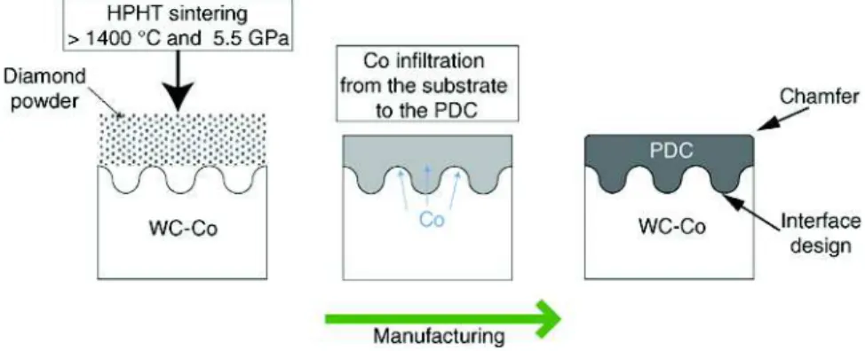
The conventional cutters are manufactured from a sintered WC–Co substrate (Fig. 1). A diamond powder is first put on the substrate and is then sintered with it under high pressure and high temperature (i.e. HPHT process) over 1400 °C and 5.5 GPa. During this step, the diamond grains form a dense skeleton and the liquid cobalt infiltrates this micro-structure from the substrate. The amount of cobalt displaced in the PDC part is homogeneous and is function of the diamond grains size[15]. Fi-nally, a surface finishing is performed and a chamfer is realized on the PDC part.
As well known by the manufacturers, PDC cutters with a fine grain distribution are more resistant to abrasion than cutter with coarse grains[3]. Inversely, a coarse diamond microstructure produces cutters more impact resistant than with fine grains. In this way, two different references of cutters were selected: F cutters with a fine distribution of diamond grains and C cutters with coarse diamond grains. These cut-ters were also associated to two different conditions of high pressure and high temperature process (HPHT): HPHT1 and HPHT2. The HPHT2 cycle was set at a higher sintering pressure with a shorter dwell time than the HPHT1 cycle. The HPHT1 and HPHT2 cycles were re-spectively performed on cutters referenced with an index 1 (F1 and C1 cutters) and an index 2 (F2 and C2 cutters). The diamond grains were observed by fractures in the PDC part realized by impact tests. The SEM fractographies of the cleft surfaces reveals a mean grains size of 6 ± 1 μm for the F cutters (Fig. 2a) and 17 ± 4 μm for the C cutters (Fig. 2b).
The WC–Co substrates are quite similar for all the conventional cut-ters with a mean cobalt content of 11.4 ± 0.1 wt.%, a mean WC grain size of 1.7 ± 0.4 μm and a mean hardness of 1359 ± 9 HV 2 kg/10 s (Fig. 3
andTable 1).
The infiltration of cobalt into the PDC part during the HPHT pro-cess produces a gradual cobalt content in the substrate and a local depletion of cobalt near the WC–Co/PDC interface. This depletion of cobalt implies a greater hardness toward the interface. Ther et al.
[16]showed that the cycle HPHT2 induces a greater hardness of the substrate near the interface than with the HPHT1. This is here well displayed by the difference of hardness ranges in the substrates which is about 38% between the cutters treated by HPHT1 and HPHT2.
The increase of hardness in the substrates near the interface can im-prove the cutter flank wear resistance which is not studied here (e.g. erosion wear by the drilling mud). In addition, the HPHT2 cycle, through its higher sintering pressure, should also enhance the bonding between the diamond grains and then increase the mechanical properties of the PDC part.
2.2. Graded cutters
Comparing to the conventional cutters, the manufacturing of the graded cutters has two additional steps defining the reactive imbibition process (Fig. 4). The BN coating is put on the sintered WC–Co substrate surface. In addition, an imbibition material rich in cobalt at 65 wt.% (Co65), is also place under the sintered substrate. The BN coating reacts with the cemented carbide material and form finely dispersed boride phases in the substrate near its surface[17]. The cobalt from the Co65 material migrates into the substrate and creates a graduation of cobalt in the WC–Co part with a core rich in cobalt. The graded cutters were also submitted to the two different conditions of sintering HPHT1 and HPHT2. Therefore, there is four references of graded cutters based on the conventional F and C cutters: F–G1, F–G2, C–G1 and C–G2.
Except the graduation of cobalt, the WC–Co substrate and the PDC part microstructures are based on the conventional cutters. The dia-mond and WC grain sizes are similar between the conventional and the graded cutters. The imbibition process clearly acted on the cobalt and the hardness distribution in the graded substrate. The mean cobalt content is 13.2 ± 0.3 wt.% which is 16% greater than the non-graded substrates (Table 2). The discrepancy of the cobalt content is also great-er for the graded cuttgreat-ers. The mean hardness is 1265 ± 12 HV 2 kg/10 s which is 7% lower than the non-graded substrates. The hardness ranges are obviously greater than for the associated conventional substrates with a difference of 36% for the F–G1 and F–G2 cutters, 21% for the C– G1 and 44% for the C–G2.
The increase of cobalt in the substrates core improves the toughness of the cutters. The borides form in the substrates near the PDC/WC–Co interface should also improve the wear resistance of this part. As the
infiltration strongly depends on the diamond grains size, the PDC part cobalt content is not influenced by the imbibition process. However, the borides should reduce the residual stresses in traction in the PDC by reducing the difference between the thermal expansion of the WC– Co substrate and the PDC part.
3. Experimental procedure 3.1. Wear experiments
A vertical lathe-type device was used to simulate drilling conditions. Cutters brazed on sample holders were adjusted downward on the lathe shaft. The counterfaces were made of a manufactured mortar rock (1 m in external diameter, 0.5 m in internal diameter and 0.6 m thick). These mortar have homogeneous physicochemical and mechanical properties (Table 3). The high quartz content of the mortar gives its abrasive characteristic.
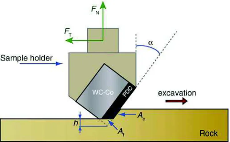
The experiments were carried out according to the following drilling conditions: normal load FNranged from 3000 to 5000 N, back rake angle
α at 15°, penetration depth of 2 mm and mean cutting speed of 1.8 m s−1(Fig. 5).
The tests were conducted in atmospheric environment and no lubri-cant was added into the contact in order to signifilubri-cantly wear the PDC cutters. During experiments, a wear flat area Afis formed at the tip of
the cutter. The height of material lost h was measured to calculate the cutting active area Acand the cutter worn volume Vc.
3.2. Cutters quality assessment
The assessment of cutters quality is made by the calculus of the qual-ity factor Q (Eq.(1))[14].
Q ¼ μ
ε " LT
u
k : ð1Þ
Fig. 2.SEM fractographies of the PDC part: a — F cutter; b — C cutter.
Fig. 3.SEM micrography of a WC–Co substrate.
Table 1
Physicochemical properties of conventional cutters (with the diamond grain size DPDC, the WC grain size DWC, the substrate cobalt content pCoWC, the substrate mean hardness HWC and the substrate hardness ranges ΔHWC).
Cutter reference DPDC DWC pCoWC HWC ΔH WC (μm) (wt.%) (HV 2 kg/10 s) F1 6 ± 1 11.5 ± 0.6 1349±34 175 F2 1.7 ± 0.4 11.4 ± 0.9 1357 ± 51 244 C1 17 ± 4 11.4 ± 0.6 1359 ± 33 182 C2 11.2 ± 0.7 1370 ± 46 250
The variables μ and ε are respectively the friction coefficient and the intrinsic specific energy calculated with the Detournay–Defourny model (Eq. (2)) [18]. The total excavation distance LTwas set at
8500 m. The variables FT(t) and FN(t) represent the overall excavation
forces applied on the cutter at the time t. The constant A is a function of the parameters μ, ε and Ac.
FTð Þ ¼ μ Ft Nð Þ þ At FTð Þ0 Ac ¼ ε 8 > < > : ð2Þ
The parameter k is the wear rate which has to be determine through an Archard model (Eq.(1)). The force FNf is the normal component of
friction forces applied on the wear flat Afand L is the cutting distance.
Vc¼ k " FNf" L: ð3Þ
The parameter u is the cutting capacity which is extracted from the calculus and the exponential fitting of the cutting efficiency η (Eq.(4)).
η ¼FTð Þ0 FTð Þt ¼ exp − 1 u" L % & : ð4Þ
Finally, the dimensionless quality factor Q balances the cutter wear resistance and the cutting capacity. Thus, the lower is the wear rate and the greater is the cutting capacity, the better is the cutter quality. In this way, this model not only considers the cutters wear kinetic but also the mechanical interactions (i.e. friction and cutting) between the cutter and the rock. The quality factor gathers the information of the
cutter wear volume and the mechanical energy spent in the contact to create this wear volume and the excavated rock volume.
4. Wear results
The final worn height hfmeasured after an excavation distance of
8500 m gives first results on the cutter performances (Fig. 6). This dis-tance of 8500 m is the highest excavation disdis-tance in common for all the studied cutters. After this distance, some cutters were excessively worn and the performance comparison is then impossible. Again, the worn height results do not consider the forces applied on the cutters during the experiments. However, it is interesting to already note that the graded cutters have a lower final worn height than the associated conventional cutters. Also, the HPHT2 process clearly leads to lower worn heights.
During the wear tests, four cutters (C1, C2, F1 and F–G1) were worn with a wear flat formed over the PDC part in the WC–Co substrate. The four others cutters (F2, C–G1, C–G2 and F–G2) were only worn in their diamond part. The wear kinetic clearly increases when the wear flat spreads in the WC–Co substrate. This increase is displayed by a slope change in the Archard representation (i.e. V vs. FNf⋅ L) (Fig. 7). Finally, only a final excavation distance LTof 8500 m is considered in the
calcu-lus which limit the effect of this change of kinetic in the assessment of quality.
The quality factor results shows that the graded cutter have a greater wear resistance than the associated conventional cutters (Fig. 8). Furthermore, all graded cutters have a higher quality factor than any conventional cutter. The results are well discriminated. The HPHT2 treatment clearly creates the cutters with the highest performances.
Considering the same conditions of HPHT, the C conventional or graded cutters have a greater wear resistance than the F cutters. This
Fig. 4.Manufacturing processes of graded PDC cutters by reactive imbibition (after Ther et al.[16]).
Table 2
Physicochemical properties of graded cutters.
Cutter reference DPDC DWC pCoWC HWC ΔH WC (μm) (wt.%) (HV 2 kg/10 s) F–G1 6 ± 1 12.9 ± 1.3 1279 ± 59 238 F–G2 1.7 ± 0.4 13.6 ± 1.7 1249 ± 73 333 C–G1 17 ± 4 13.0 ± 1.1 1274 ± 49 220 C–G2 13.4 ± 2.3 1257 ± 100 359 Table 3
Mortar physicochemical and mechanical properties.
Density Quartz content Young modulus Compressive strength
(kg m−3) (wt.%) (GPa) (MPa)
result is unexpected as the cutters with finer diamond grain distribution usually have a higher wear resistance. Finally, the best cutter is the C–G2 graded with a coarse diamond microstructure and manufactured under the cycle HPHT2.
5. Worn surfaces analyzes 5.1. Observations
The diamond microstructure is not observable on the wear flats and only macroscopic wear mechanisms are visible in the PDC part. For all the cutters, when the wear flat is only in the diamond part, a relatively smooth worn surface is observed (Fig. 9a). When the wear flat reaches the WC–Co part, abrasive scratches are displayed along the excavation direction (Fig. 9b). In this case, white debris, meanly formed of rock par-ticles, is accumulated at the interface PDC/WC–Co.
SEM observations of the wear flat in WC–Co part highlights a deple-tion of the cobalt matrix revealing the prismatic form of the WC grains (Fig. 10). Transfers of rock particles are included in the WC–Co microstructure.
5.2. Profilometry measurements
Topographies of the wear flats were performed with an optical profilometer (Wyko NT1000). These topographies display the abrasion scratches in the PDC part and in the WC–Co part when the wear flat is also in the substrate (Fig. 11). More particularly, the worn cutters show the formation of voids in the cemented carbide near the interface. These voids can explain the accumulation of debris on the wear flat pre-viously observed.
The roughness was evaluated by the profile arithmetic average Raon
the cutter of the cycle HPHT2 (Table 4). These measures were done in the PDC part on F2, F–G2, C2 and C–G2 cutters worn across the PDC/ WC–Co interface. The roughness values indicate that the cutters C with a coarse granulometry may produce deeper scratches than cutters F. Moreover, the graded cutters have lower roughness values than the conventional cutters. This implies that the graduation process act on the PDC microstructure and its mechanical properties.
5.3. Chemical analyzes
Raman analyzes were carried out in the PDC part of an unworn cut-ter C1 and in the PDC part of a worn cutcut-ter C1 in the wear flat. Before the Raman measurements, the PDC worn surface was cleaned to limit the detection of rock particles. These analyzes were performed with a Raman confocal spectrometer (Horoba Labram HR 800). This device uses an argon green laser with a wavelength of 532 nm, a power of 21.4 mW and calibrated with a silicon sample. The focal spot is about 720 nm on the cutter surface. Considering an absorption coefficient of 2 ⋅ 107m‐1for a PDC material with 3% of cobalt[19], the maximum
beam penetration can be estimated at 25 nm. The Raman measure-ments are then limited to the surface of the PDC.
The Raman spectra obtained with focus on the wear flat, in the PDC part, of the cutters display a peak at 1332 ± 0.1 cm− 1(Fig. 12a). This Fig. 5.Cutter/rock contact configuration of the vertical lathe with FNand FTthe applied
forces, α the back rake angle, Acthe cutting active area and Afthe wear flat area.
Fig. 6.Final worn height hfof conventional and graded cutters (LT=8500m).
Fig. 7.Wear kinetic of the cutter C–G1 worn over its interface PDC/WC–Co (LT=19720m): wear volume vs. the product FNf⋅ L and the excavation distance L.
peak represents the sp3bond of diamond. Obviously, this peak can also
been observed in the PDC part of an unworn cutter surface at 1333.9 ± 0.04 cm−1. The peak shift is then due to the residual stresses in the PDC
part of the new cutters[20]. These residual stresses are relaxed near the wear flat during experiments. Two other peaks are observed at 1359.7 ± 0.5 cm− 1, broadening the diamond peak (Fig. 12b), and at
1580 ± 0.1 cm− 1on the spectra both corresponding to a sp2bond.
These positions are characteristic of graphite and confirm the transfor-mation of metastable diamond on the worn PDC surface during excava-tion as a wear mechanism. In addiexcava-tion, a large peak is observed between 1400 cm− 1and 1500 cm− 1corresponding to another sp2bond. This
highlights that the PDC also undergoes an amorphization during wear. This amorphization also acts on the broadening of the sp3diamond
peak[21].
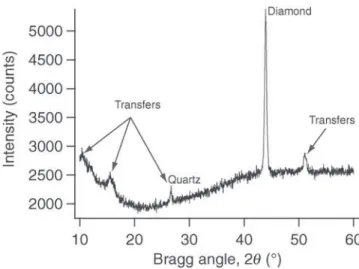
To complete these chemical analyzes, XRD measurements were per-formed using a diffractometer (X'PERT Philips MRD) with CuKα radia-tion source beam at 40 kV and 50 mA. The XRD analyzes were carried out with 2θ Bragg angles from 10° to 60° and a step size of 0.02°. These measurements were focused in the PDC part on the wear flat. The diffractograms show the sharp diamond peak at 43.92°[22]and others peaks corresponding to transfers from the rock on the wear flat (Fig. 13). One of these transfers was identified as the quartz particles with the (101) peak at 26.64°[23]. The cobalt phase is not visible on the diffractograms of the worn surfaces. The irregular form of the diffractograms background also indicates that amorphous material from the rock is transferred on the cutters. The graphite is not detected
with XRD technique because of the interference of its peaks on the diffractogram with the ones of the rock transfer. The most intense peak of the graphite is to close to the quartz (101) peak at a 2θ Bragg angle of 26.611°[24]. The other peaks are hidden by the XRD signal background.
6. Discussions 6.1. Wear mechanisms
The PDC worn surfaces are difficult to characterize. The abraded polycrystalline microstructure is hardly visible by optical or SEM obser-vations. However, based on the literature and the results obtained in this work, wear mechanisms of PDC cutters can be proposed here. An analysis of the different material flows inside and outside the contact helps to describe the contact dynamics[25]. In this approach, the tribo-logical cycle deals with:
• The particles detachment from the PDC part, the WC–Co part (if the wear flat reaches the substrate) and from the rock generates the source flow Qs. This flow is then mainly composed by abrasive quartz
particles extracted from the mortar ring;
• The circulation of these particles in the contact (third body) forms the internal flow Qi. The internal flow leads the wear debris to
accommo-date the velocity gradient in the contact;
• If debris leaving the interface come back in the sliding contact, this particles defines the recycling flow Qr. As the cutter/rock contact is
refreshed by the cutting action, this flow cannot be considered here;
Fig. 9.Optical microscope observation of the C–G1 wear flat: a — wear flat only in the PDC part (LT=1360m); b — wear flat spread in the WC–Co substrate (LT=19720m).
Fig. 10.SEM observation by backscattered electron analysis of C–G1 wear flat near the interface in the WC–Co substrate (LT=19720m): the PDC part and the rock particles are black and the prismatic WC grains are white.
Fig. 11.Optical profilometer topography of the C1 wear flat spread in the WC–Co substrate (LT=17680m).
• The wear flow Qwis created when particles from the third body
defin-itively leaves the contact.
In a kinematic point of view, during the rock excavation, quartz par-ticles are introduced in the cutter/rock contact. Then, these abrasive particles may provoke intergranular and transgranular cracks propaga-tion in the sintered diamond skeleton (microcutting acpropaga-tion) and remove diamond grains and fragments of these grains. In the same time, the ductile cobalt phase surrounding the diamond grains is also extracted and goes in the interface. When the wear flat reaches the WC–Co sub-strate, the quartz particles remove the cobalt binder leading to the decohesion and the extraction of WC grain fragments[26]. After this critical stage, the wear alternate between the WC–Co and the harder PDC part.
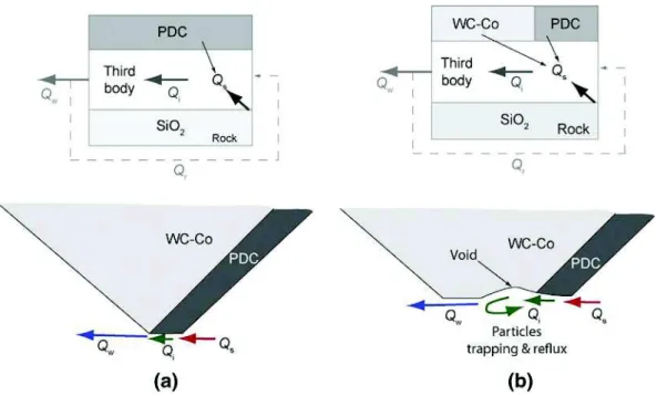
The cutters wear is then mainly created by the circulation of abrasive quartz particles. Therefore, the wear kinetic increases if the flow of quartz particles grows or if these abrasive particles are stabilized in the contact. The stabilization of particle in the sliding contact occurs when the wear spreads in the WC–Co substrate. Indeed, as seen above, voids are formed in the substrate part of the wear flat generating debris trapping in the contact (Fig. 14). A part of the debris flows back to the PDC part increasing the wear rate of the cutter. In addition, a greater amount of cobalt is introduced in the contact from the WC–Co substrate. This greater binder phase flow bring more stabilization and cohesion to abrasive particles under the wear flat which could also explain a wear rate increase[27].
Finally, the thermal wear and more generally the tribological trans-formed structures are other significant mechanisms occurring in the cutter/rock contact. The PDC is transformed in graphite or in amorphous carbon on the wear flat. These new phases are then easily abraded by the rock. In extreme thermomechanical conditions, the TTS lead to the highest wear kinetics. In this study, the thermal wear is a minor mech-anism regarding to the abrasive wear. Indeed, this wear is associated to smooth wear surfaces or to visible wear scars (grain boundary weaken-ing and grain pullouts)[5]. In this study, the wear flats (spread in the
PDC and the WC–Co substrate) display macroscopic abrasive scratches along the excavation direction.
6.2. Cutter properties and wear
As seen above, at equivalent manufacturing process, C cutters have greater quality factors than F cutters. In this way, other parameters can be predominant and can be more influential than the diamond grain size of the PDC cutters on wear. Even if coarse grains lead to deeper abrasive scratches, the energy needed to create intergranular crack and pullout diamond grains during wear can depend on various parameters (e.g. the cohesion between the grains and the residual stresses in the PDC[14]).
Next, as expected, the highest conditions of the HPHT2 cycle lead to a better wear resistance. Again, this can be explained by a better bridg-ing realized between the diamond grains durbridg-ing sinterbridg-ing. In this way, the HPHT2 cycle reduces the propagation of intergranular cracks in the PDC microstructure and then the abrasion of cutters.
Eventually, the graded cutters show a greater wear resistance than the conventional cutters. The reactive imbibition and the boride forma-tion may chemically influence the diamond microstructure and act on toughness of the PDC cutters. In addition, the borides formed at the PDC/WC–Co interface reduce the thermal expansion coefficient differ-ence between the substrate and the diamond part. This should induce
Table 4
Wear flats roughness in the PDC part of cutters F2, F–G2, C2 and C–G2 considering a zone of 2mm×2mm (LTN 14000m).
Cutters F2 F–G2 C2 C–G2
Ra(±0.3 μm) 2.9 2.4 4.5 3.2
Fig. 12.Raman spectra of the C1 PDC part: a — spectrum centered on the sp3peak for an unworn and a worn cutter; b — global spectrum with focus on the wear flat. Fig. 13.XRD analysis of the C1 wear flat in the PDC part.
a lower residual stresses gradient in the cutter and then reduce the re-sidual stresses in traction (i.e. axial and shear components[14]) in the diamond part. Another interest of borides could appear when the cut-ters are worn until the WC–Co substrate. The hardening of the WC–Co by these borides should limit voids formation and cobalt depletion near the interface. Consequently, the trapping, the stabilization and co-hesion of abrasive debris in the contact could be moderated by the reac-tive imbibition process.
Finally, the results show that the reactive imbibition process can sig-nificantly enhance the abrasive wear resistance of cutters with coarse diamond grains. In other word, graded cutters based on potentially im-pact resistant microstructure can also be characterized by a high wear resistance.
7. Conclusion
The excavation performances and the wear behavior of conventional PDC cutters and graded PDC cutters by reactive imbibition were charac-terized. The results concerning the relation between cutters properties and the wear performances, show that:
• The control of the HPHT process conditions can enhance the wear re-sistance by realizing a better bridging between the diamond grains; • The diamond grains size is not necessarily the main factor influencing
the wear behavior of cutters;
• The reactive imbibition process enhances the wear resistance of the cutters;
• Potentially impact resistant PDC cutters, because of a coarse diamond microstructure, can also be wear resistant by performing a reactive imbibition process.
Regarding to a third body approach, different wear mechanisms are highlighted:
• As in the real conditions of excavation, abrasion is the main wear mechanism here. Detached quartz particles from the rock produce longitudinal scratches on the cutter along the cutting direction; • The wear rate increase produced when the wear flat spreads in the
substrate can be explained by the formation of voids. Quartz particles are then trapped in these voids and a more severe abrasion is then
realized. A greater flow of cobalt introduced in the contact could also explain an increase of wear kinetic. The reactive imbibition pro-cess limit the formation of these voids and the flow of cobalt at the in-terface;
• The transformation of diamond in graphite and amorphous carbon during the excavation is clearly identified here as a secondary thermomechanical wear mechanism.
Acknowledgments
This work was developed during the thesis of the University of Tou-louse “Tribological behavior of polycrystalline diamonds and graded cemented carbides WC–Co — Application to drill bits inserts and cutters for the drilling of abrasives rock formations ” under the program ANR-09-MAPR-0009 of Agence Nationale de la Recherche[28]. We thank Armines Matériaux laboratory and the Varel Europe company for the elaboration of the PDC cutters used in this study and for their useful discussions.
References
[1]J. Cortes, A. Besson, Behavior of polycrystalline diamond compact cutters while dril-ling in bottomhole conditions — field applications, Tech. rep., Total — Compagnie Française des Pétroles, 1981.
[2]J.L. Wise, D.W. Raymond, C.H. Cooley, K. Bertagnolli, Effects of design and processing parameters on performance of PDC drag cutters for hard-rock drilling, Tech. Rep., Sandia National Laboratories, 2002.
[3]F. Bellin, A. Dourfaye, W. King, M. Thigpen, The current state of PDC bit technology, World Oil 2010, pp. 67–71.
[4]A. Ersoy, M. Waller, Wear characteristics of PDC pin and hybrid core bits in rock dril-ling, Wear 188 (1995) 150–165.
[5]L.E. Hibbs, G.C. Sogoian, Wear mechanisms for polycrystalline-diamond compacts as utilized for drilling in geothermal environments, Tech. Rep., Sandia Laboratories, 1983.
[6]Q.S. Bai, Y.X. Yao, P. Bex, G. Zhang, Study on wear mechanisms and grain effects of PCD tool in machining laminated flooring, Int. J. Refract. Met. Hard Mater. 22 (2004) 111–115.
[7]D. Miess, G. Rai, Fracture toughness and thermal resistance of polycrystalline dia-mond compacts, Mater. Sci. Eng. A 209 (1–2) (1996) 270–276 (proceedings of the 5th International Conference on the Science of Hard Materials).
[8]D.A. Glowka, Implications of thermal wear phenomena for PDC bit design and oper-ation, 6Oth Annual Technical Conference and Exhibition of the Society of Petroleum Engineers, 1985.
Fig. 14.Tribological circuit diagram with flows Qs, Qi, Qwand Qr(respectively source flow, internal flow, wear flow and recycling flow) and circulation of particles under the wear flat in the contact cutter/rock: a - wear only in the PDC; a wear spread in the WC–Co substrate.
[9] E. Sauger, S. Fouvry, L. Ponsonnet, P. Kapsa, J.M. Martin, L. Vincent, Tribologically transformed structure in fretting, Wear 245 (2000) 39–52.
[10] A. Lisovsky, The migration of metal melts in sintered carbides, Powder Metall. Int. 19 (1987) 18–21.
[11] E. Lefort-Sorlier, C. Colin, A. Dourfaye, Gradation process by imbibition in WC–Co for mining tools application, Advanced Materials Research, vol. 83–86 2009, pp. 810–817.
[12] C. Colin, E. Sorlier, A. Dourfaye, Process for manufacturing a part comprissing a block of dense material constitued of hard particles and of binder phase having a gradient of properties, and resulting part, US Patent 8,602,131 (2013).
[13] A. Dourfaye, C. Colin, E. Sorlier, H. Sellami, Process for the production of an element comprising at least one block of dense material constituted by hard particles dis-persed in a binder phase: application to cutting or drilling tools, US Patent 8,647,562 (2014).
[14] M. Yahiaoui, L. Gerbaud, J.-Y. Paris, J. Denape, A. Dourfaye, A study on PDC drill bits quality, Wear 298–299 (2013) 32–41.
[15] S.-M. Hong, M. Akaishi, H. Handa, T. Osawa, S. Yahmaoka, Behaviour of cobalt infil-tration and abnormal grain growth during sintering of diamond on cobalt substrate, J. Mater. Sci. 23 (1988) 3821–3826.
[16] O. Ther, C. Colin, L. Gerbaud, A. Dourfaye, Reactive imbibition of WC–Co substrate for PDC cutters used in oil and gas and mining drilling, Powder Metallurgy World Congres & Exhibition, 2012.
[17] M. Yahiaoui, J.-Y. Paris, J. Denape, A. Dourfaye, Wear mechanisms of WC–Co drill bit inserts against alumina counterface under dry friction: part 2 — graded WC–Co in-serts, Int. J. Refract. Met. Hard Mater. 48 (0) (2015) 65–73.
[18] E. Detournay, P. Defourny, A phenomenological model for the drilling action of drag bits, Int. J. Rock Mech. Min. Sci. Geomech. Abstr. 29 (1992) 13–23.
[19] J. Hubbell, S. Seltzer, Tables of X-ray Mass Attenuation Coefficients and Mass Energy-Absorption Coefficients from 1 keV to 20 MeV for Elements Z = 1 to 92 and 48 Ad-ditional Substances of Dosimetric Interest, 1989.
[20] S.A. Catledge, Y.K. Vphra, R. Ladi, G. Rai, Micro-Raman stress investigations and X-ray diffraction analysis of polycrystalline diamond PCD tools, Diam. Relat. Mater. 5 (1996) 1159–1165.
[21] R. Shroder, R. Nemanich, Analysis of the composite structures in diamond thin films by raman spectroscopy, Phys. Rev. B 41 (1990) 3738–3745.
[22] K. Hakuna, H. Maeta, K. Ohashi, T. Koike, JCPDS-ICDD XRD Card Diamond, syn 00– 065-0537, 1981.
[23] P. Norby, JCPDS-ICDD XRD Card Quartz 01–087-2096, 1997.
[24] H. Lipson, A. Stokes, JCPDS-ICDD XRD Card Graphite 01–075-2078, 1997.
[25] Y. Berthier, Maurice Godet's third body, in: D. Dowson, C. Taylor, T. Childs, G. Dalmaz, Y. Berthier, L. Flamand, J.-M. Georges, A. Lubrecht (Eds.), The Third Body Concept Interpretation of Tribological Phenomena, Vol. 31 of Tribology SeriesElsevier 1996, pp. 21–30.
[26] J.L. Chermant, F. Osterstock, Fracture toughness and fracture of WC–Co composites, J. Mater. Sci. 11 (1976) 1939–1951.
[27] M. Yahiaoui, J.-Y. Paris, J. Denape, A. Dourfaye, Wear mechanisms of WC–Co drill bit inserts against alumina counterface under dry friction: part 1 — WC–Co inserts with homogenous binder phase content, Int. J. Refract. Met. Hard Mater. 48 (0) (2015) 245–256.
[28] M. Yahiaoui, Comportement Tribologique de Diamants Polycristallins et de Carbures Cémentés WC–Co Avec Traitements de graduation — Application Aux Inserts et Taillants D'outils Pour le Forage de Formations Rocheuses Fortement AbrasivesPh.D. Ph.D. thesis Université de Toulouse, 2013.