OATAO is an open access repository that collects the work of Toulouse
researchers and makes it freely available over the web where possible
Any correspondence concerning this service should be sent
to the repository administrator:
[email protected]
This is an author’s version published in:
https://oatao.univ-toulouse.fr/
2
6080
To cite this version:
Das, Pritam
and Remigy, Jean-Christophe
and Lahitte, Jean-François
and van der Meer, Andries D. and Garmy-Susini, Barbara and Coetsier, Clémence
and Desclaux, Sandrine
and Bacchin, Patrice
Development of double
porous poly (ε - caprolactone)/chitosan polymer as tissue engineering scaffold.
(2020) Materials Science and Engineering C, 107. 110257. ISSN 0928-4931.
Official URL:
https://doi.org/10.1016/j.msec.2019.110257
Development of double porous poly
(ë -
caprolactone)/chitosan polymer as
tissue engineering scaffold
Pritam Das
a,
b,
c, Jean-Christophe Remigy
a, Jean-François Lahitte
a, Andries D. van der Meer
b,
Barbara Garmy-Susini
C, Clémence Coetsi�, Sandrine Desclaux
a,
Patrice Bacchin
a,*
• Laboratoire de Génie Chimique, Université de Toulouse, CNRS UMR, 5503, INPT, UPS, Toulouse, J'tance
"University of Twenre, Applled Stem Cel! Technologies, TechMed Centre, Faculty of Science and Technology, Enschede, 7500, AE; the Netherlands 'Insdrut des maladies métaboliques et cardiovasculaires (12MC), Université de Toulouse, mserm UI 048, UPS, Toulouse, J'tance
Keywords: Poly (• -caprolactone) Otltosan Double porous Membrane Blocompatlblllty Cell ClÙture
1. Introduction
A B S T R A CTPolymer blend made from poly(E - caprolactone)/chitosan (PCL/CHT) offers interesting opporttmities for bio logical applications. The paper presents a new way to fabricate PCL/CHT double-porosity (macrovoids with interconnected microporosity) membrane materials from a chemical optimiz.ation of the solvent and non-solvent phases and from a moclified phase inversion technique. By varying the PCL/CHT proportion, it is shown that it is possible to improve the chemical and physical properties of the CHT carbohydrate polymer. The PCL/CHT
membranes are fully characterized in term of physico-chemical properties (ATR-FTIR, XRD and DSC) to tm derstand the miscibility of the two-polymer blend. Morphological characterization by SEM shows that by in
creasing CHT wt% in the blend, the size of the macrovoids was increasing. Rapid enzymatic degradation of PCL from ail the blend was found by using lipase (from P. cepacia). The mechanisms at the origin of the morpho
logical structuration of the material is also discussed. To test the ability to operate these materials as small cliameter vascular scaffolds, cell culture with human umbilical vein endothelial cells (HUVECs) were carried out on the membrane and the results analyzed with laser scanning confocal microscopy (LSCM). Data suggest that
the blend membrane with higher concentration of CHT polymer wt% have suitable properties that promote high
number of cells on the surface by maintaining cellular cytoskeleton integrity within 3 days. The blend membrane with a double porous morphology could be potentially applicable in future for small cliameter vascular graft application. The surface macrovoids (20-90 µm) could be useful for three-dimensional cellular adhesion and proliferation and interconnected microporous spongy network (7-20 µm) is expected to transfer essential nu trients, oxygen, growth factor between the macrovoids and the supernatant.
Tissue engineering relies on the use of artificial degradable porous material scaffold integrated with biological cells or molecules to re generate tissues [1]. The scaffold material should offer specific func
tionalities to accomplish this goal. Severa! studies show that 3D struc tures of the support material control the cell growth [2]. The material composition is a key point that controls the biocompatibility, the cell adhesion and optionally the biodegradability. The material engineering must be tailored to the biological strategy. In recent studies, artificial vascular grafts generally have been fabricated from synthetic polymers, such as polyester, e.g. polycaprolactone (PCL) or polylactic acid (PLA)
or polylactic-co-glycolic acid (PLGA) or polyurethane [3,4]. This kind of polymer scaffolds can pro'l'ide sufficient mechanical strength and are considered biocompatible and biodegradable without any toxic by products. However, they are hydrophobie in nature and Jack reactive functional sites for further bio-functional modification [5] which led to the development of innovative hybrid materials by mixing both syn thetic and natural polymers [6]. Natural carbohydrate polymers like chitosan (CHT) on the other hand can provide an excellent candidate for biomedical vascular grafts application, mostly in combination with other synthetic polymers [7-11]. CHT is a linear polysaccharide com posed of glucosamine and N-acetyl glucosamine units connected through ft-1,4-glycosidic bond and produced from the highly abundant
Abbreviations: PCL, Poly (E- caprolactone); CHT, Chitosan; HUVEC, Human umbilical vein endothelial cells; EGM-2, Endothelial growth meclium -2; DAPI, 6-Diamidino-2-Phenylindole; BSA, Bovine serum albumin; PBS, Phosphate-buffered saline
• Corresponding author. Laboratoire de Génie Chimique, Université de Toulouse, CNRS, INPT, UPS, Toulouse, France.
observed by SEM and the physico-chemical properties of the blends were characterized by ATR-FTIR mapping, XRD and DSC. In addition, enzymatic degradation study was performed by using lipase (from Pseudomonas cepacia; 7U/ml) at 37 °C in phosphate buffer saline (PBS) at physiological pH. Change in morphological properties and weight loss (%) were monitored at predetermined time intervals of the de-gradation study. To test the biocompatibility and potentialities of the membranes as a small diameter vascular graft for cardiovascular system disease, cell culture was performed with human umbilical vein en-dothelial cells (HUVECs) up to 3 days and results were observed in laser scanning confocal microscopy.
2. Materials and methods 2.1. Materials
CHT (MW 190–310 kDa, 75–85% de-acetylation degree, CAS Number 9012-76-4) was purchased from Sigma-Aldrich and PCL (MW 80 kDa, CAPA™ 6800, CAS Number 24980-41-4) was purchased from Perstorp Holding AB, Sweden. Isopore® Polyester (PET) track-etched membranes (with 10 μm pore diameter), used as macrovoid generator, were purchased from Sterlitech, USA. Acetic acid, formic acid, sodium
hydroxide and sodium azide (NaN3) were purchased from
Sigma-Aldrich. Lipase from Pseudomonas cepacia (activity: 35U/mg, CAS Number 9001-62-1) were purchased from Sigma-Aldrich. Phosphate buffer saline (PBS) was purchased from Fisher Scientific (CAS Number 7778-77-0). Human umbilical vein endothelial cells (HUVECs) were purchased from Lonza and the corresponding culture medium (EGM-2: basal medium with supplement mix, CC-22011) was obtained from Promocell. Collagen I (rat-tail) were obtained from Santa Cruz. Trypsin-EDTA, Formaldehyde, 6-Diamidino-2-Phenylindole (DAPI), and Alexa Fluor 488 Phalloidin were purchased from Thermo Fisher. Triton X-100, bovine serum albumin (BSA) were purchased from Sigma Aldrich. 2.2. Methods
2.2.1. Development of the membrane with a double porosity level The membranes were developed by modified liquid induced phase inversion method by diffusion between a solvent as formic acid/acetic acid (FA/AA) mixture and non-solvent as NaOH aqueous solution. PCL and CHT with a ratio 100/0, 90/10, 80/20 and 70/30 (w/w%) were dissolved in FA/AA (w/w%) mixture. The polymer concentration in the solution was expressed in wt.% as followed:
= + CHT(wt. %) 100 Mass Mass Mass CHT CHT PCL (1) = + + +
Polymer(wt. %) 100 Mass Mass
Mass Mass Mass
CHT PCL
CHT PCL Solvents (2)
The polymer solution was casted on a glass plate using a casting knife in order to achieve a thickness around 250 μm at 23 °C. The track-etched membrane was at first immersed in the solvent mixture to fill the pores with solvent mixture, slowly wiped out to remove excess solvent
and slowly applied on the casted polymer solution (Fig. 1).
The glass plate was then gently immersed in a non-solvent bath containing NaOH solution at 23 °C. Immediately after the immersion, demixing via neutralization of the acidic casted solution was started due to solvent exchange leading to the flat sheet membrane formation in few minutes (in case of PCL/CHT 100/0) to hours (in case of PCL/ CHT 70/30). It should be noted that this quenched phase inversion method leads to a thermodynamically non-equilibrium state of the polymers in the final membrane and two different kinds of porous
structures were formed in the same conditionFig. 1.
The solvent exchange rate was spatially quite homogeneous where the polymer solution was not covered by the track-etched membrane leading to single porous structure without enough open pores on the top natural polymer, chitin. It is biocompatible, bioresorbable, hydrophilic
and non-toxic. It has high affinity towards proteins and provides anti-bacterial, hemostatic, fungistatic, antitumor and anticholesteremic
properties [12–16]. It can provide a favorable environment for cell
attachment as chemical structure of CHT is similar to glycosaminogly-cans (GAGs), which are native components of extracellular matrix
(ECM) [17,18]. However, it has low mechanical properties in wet
conditions and high hydrophilicity, which can be easily optimized by blending with synthetic polymers. Blending can also improve the low degradation rate of the synthetic polymers in physiological conditions. It is well accepted that blending these two kind of polymers will be very advantageous, which can significantly reduce all the disadvantages and combine the benefits of the individual polymers providing a superior material with good tissue compatibility and sufficient mechanical
strength [19–21]. The 3D structure of the material should enable to
host the cells but also to distribute the nutrients and to favor the re-moval of cellular metabolic products.
In the last decades, various scaffolds h ave b een d eveloped more often from an assembly of simple fibers. The study of PCL/CHT blend with electrospinning method is extensively researched and well adap-table for better cell attachment with good dynamic properties [9,10,12,19–25]. However numerous studies report on the difficulties encountered for electrospinning pure chitosan as the structure is
me-chanically weak, limiting practical processing [26–29]. Furthermore, it
is difficult to manage the multiple functionality requirements with an assembly of fibers. T he u se o f m embranes a ppears a s a n interesting alternative to tune the porosity and to manage the mass transport properties. The different level of membrane porosity can be adjusted in order to have both macrovoids to host the cells and interconnected
micropores network to ensure the transportation of molecules [30].
Solvent mixing with PCL and CHT was more conveniently used com-pared to melt blending which is quite difficult to perform as CHT de-composes before undergoing melting. Although it is also difficult to make a homogeneous blend in solvent mixing due to the high viscosity of CHT in solvent and also the scarcity of good mutual solvents. Several
efforts were made as Honma et al. [25,31] produced PCL/CHT blend
casting by using common solvent as 1,1,1,3,3,3-hexa-fluoro-2-propanol (HFIP) solution. They showed that PCL/CHT can be processed by using HFIP but this solvent is very expensive, carcinogenic and difficult to
remove during washing [32]. Although a different a pproach w as
re-ported to find a good mutual solvent [33–38]. Among them a suitable
approach could be to dissolve CHT in 0.5 M acetic acid and PCL in
glacial acetic acid where the authors [35] were able to obtain a mixture
of these two solutions at a low concentration of polymer but it was not
effective at high concentration [31] as in our case. In another study, a
solvent mixture of formic acid/acetone was reported to be used to de-velop PCL/CHT nanofibers at high concentration of polymers. In this case, it was forming beads-like morphology indicating incomplete
dis-solution of the polymer [39]. Recently, formic acid/acetic acid mixture
[40] with certain ratio has produced a mutual solvent for both polymers
with minimal degradation and phase segregation but with faster
dis-solution. Despite so many combination of solvents, the author [40]
have reported that the formic acid/acetic acid mixture produced the bead free and least toxic scaffold and the solvent can be easily removed during washing.
Here we propose a new scaffold b ased o n p olymer membrane technologies to meet the needs and the constraints discussed above. The main objectives are to obtain a biocompatible and biodegradable ma-terial with open macrovoids for three-dimensional cell culture and in-terconnected microporosities to transport nutrients, oxygen, between the macrovoids and supernatant. The membranes were fabricated from a PCL/CHT blend with a modified l iquid i nduced p hase inversion technique in order to create macrovoids on the surface. The percentage ratio of PCL/CHT (100/0, 90/10, 80/20, 70/30 w/w %) blend was changed to investigate a range of chemical interactions, miscibility and biodegradability. The morphology of the developed materials was
surface. On the other hand, where the polymer solution was covered by the track-etched membrane, a heterogeneous solvent exchange was occurred leading to the formation of double porous structure. The macrovoids were formed where the non-solvent has a direct access to the polymer solution through the pores of the track-etched membrane. And, interconnected micropores were formed by diffusion of the non-solvent through the newly formed macrovoids. This mechanism was
described by Strathmann et al. [41] to explain the formation of skinned
membrane with macrovoids and sponge structure; the nascent skin playing an equivalent role like our track-etched membrane as discussed
in Sec.3.7.
After the membrane formation, when it turned opaque and detached from the glass plate, the track-etched membrane was removed gently. The PCL/CHT membrane was washed several times in ultrapure water and stored in ultrapure water at 4 °C.
The surface where the macrovoids were open towards the non-sol-vent (i.e. where the track-etched membrane was applied) is denoted as top surface and the other surface, which was facing the glass plate, is denoted as the bottom surface.
2.2.2. Viscosity measurements of the polymer solution
The viscosity of the polymer solution was measured by Rheometer
Anton Paar Physica MCR 301, France (Fig. 2). After complete
dissolu-tion of the soludissolu-tion, a 0.6 ml volume was injected on a cone plate rheometer (diameter 50 mm). The viscosity was measured at a shear
rate from 2 to 100 s−1at 20 °C. All the measurements were performed
inside a close chamber in order to avoid the solvent evaporation and dissolution of water from air moisture.
2.2.3. Scanning electron microscopic (SEM) analysis
SEM analysis (Phenom XL, Fondis Biotech, France) were done on both double and single porous membranes to evaluate all the developed
blend morphology from the top surfaces and the cross sections (Fig. 3).
All the samples were coated with gold and analysis were performed at an accelerating voltage of 10 kV. The surface porosity was also
de-termined from the SEM images by using ImageJ [42] software and
re-ported inTable 1.
2.2.4. Attenuated total reflection (ATR)-Fourier transformed infrared (FTIR) spectroscopic analysis and mapping
FTIR analysis were done by using a Nexus Nicolet (USA) FTIR
Microscope system with an ATR diamond crystal at 45° angle (Fig. 4).
Prior to the examination, 1 cm2sample was cut and measurements were
done on both surfaces (three times) of each sample. Each point was
scanned sixteen times with a resolution of 8 cm−1 and the spectral
range was 650–4000 cm−1. The ATR correction was applied on all the
Fig. 1. Double porosity development by modified liquid induced phase
inver-sion process with the following steps: PCL/CHT membrane casting, applying the track-etched membrane before immersing in non-solvent bath and removing track-etched membrane after membrane formation. SEM images of PCL/CHT 100/0 represent double porosity and single porosity on top surface and cross section of the same membrane.
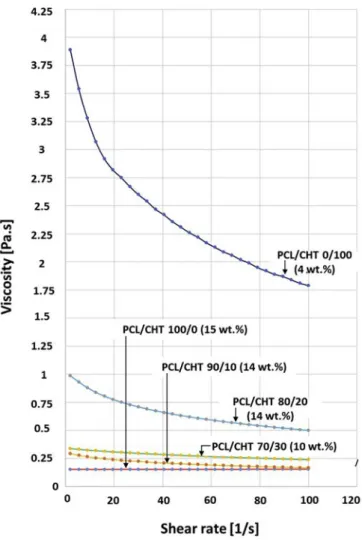
Fig. 2. Viscosity [Pa.s] vs shear rate [1/s] measurement of PCL/CHT 100/0
(15 wt%), PCL/CHT 90/10 (14 wt%), PCL/CHT 80/20 (14 wt%), PCL/CHT 70/ 30 (10 wt%) and PCL/CHT 0/100 (4 wt%) scaffolds respectively in solvent FA/ AA mixture.
spectra [43]. FTIR chemical mapping on either side of the membrane also performed using an infrared spectrometer IN10MX
Thermo-scientific (USA) with an ATR germanium crystal of a 25° angle (Fig. 5).
A square sample of 6 mm2 was studied. Data were analyzed on a
50 μm × 50 μm surface for each point (one point was measured every
50 μm) with a spectral resolution of 8 cm−1. Each measurement was
scanned by sixteen times with the spectral range 650–4000 cm−1.
2.2.5. X-ray diffraction (XRD) analysis
The crystalline structure of membrane sample (5 mm×5 mm) was
investigated by XRD analysis using a D4 Endeavor X-ray diffractometer
(CuKα1= 0.154056 nm and CuKα2= 0.154044 nm; generator 40 eV;
40 mA, Bruker AXS, Karlsruhe, Germany) from 10° to 100° at a scan
speed of 21.7 s/step that is equal to 0.02° (2-theta) as can be seen in
Fig. 6(A).
2.2.6. Differential scanning calorimetric (DSC) measurements
DSC experiments were conducted (DSC TA instrument Q2000, France) in order to evaluate thermal properties of the PCL/CHT blend
membranes (Fig. 6(B)). The membranes were dried at 37 °C and were
cut in a dimension of 3 mm2. The sample was put inside an aluminum
pan and mechanically covered by an aluminum cap. The pre-weighted aluminum pan was placed inside the DSC machine and equilibrate at 20 °C. The temperature scanning was performed at a constant heating
rate of 10 °C min−1, from 20° to 80 °C without preheating step. The
melting point (Tm) of PCL in the blend by varying CHT wt.% (pure PCL
melting point is 60 °C) determined. 2.2.7. Enzymatic degradation of the blend
The membranes were dried in vacuum at 37 °C until constant weight
was reached and were cut in 6 mm×6 mm pieces. The initial weight
(wi) was taken (in mg up to the fifth decimal point). Then the samples
were placed in a 5 ml vials containing 3 ml of PBS 1 × solution, 0.6 mg
(7U/ml) of lipase (from Pseudomonas cepacia) and 0.05 wt% NaN3. The
entire procedure was done in a sterile condition and vials were sealed and stored in incubator at 37 °C. The enzyme solution was changed every day in order to maintain the same enzymatic activity during the whole process. The same procedure was done without the enzyme as a control. Three consecutive samples were taken out after 6 h of in-cubation and every one-day intervals until 10 days. The samples were washed with copious deionized water, dried at 37 °C in vacuum until
constant weight. The final weight, Wf, was taken.
The weight loss, W %loss , was calculated by the following equation
and can be seen inFig. 8(A) and (C) :
= W W W W % 100 loss i f i (3)
where,Wi, is the initial weight and, Wf, the final weight.
Scanning electron microscopic images of the degraded membranes (Fig. 9) were taken and the ageing solution was collected to observe the
change in pH (Fig. 8(B)).
2.2.8. Cell culture and study by laser scanning confocal microscopy Membranes were cut with diameter of 2.2 cm and washed with sterile phosphate-buffered saline (PBS) three times. The samples were put in 12 well plate and kept in sterile PBS suspension at 4 °C for overnight before the cell seeding. Then the samples were washed again with sterile PBS, 1 ml collagen I (0.1 mg/ml in PBS) was added in the well plate and incubated for 30 min at 37 °C. Then the well plate was taken out from the incubator, washed with PBS and incubated for 1 h Fig. 3. SEM micrographs of membranes on the top surface and cross section
with double porosity (using track-etched membrane): (A, B) PCL/CHT 100/0,
(C, D) PCL/CHT 90/10, (E, F) PCL/CHT 80/20, (G, H) PCL/CHT 70/30. Single
porosity (without using track-etched membrane): (I, J) PCL/CHT 100/0, top surface and cross-section, respectively.
Table 1
Summary of the polymer blend membrane properties with distinct concentra-tion in correlaconcentra-tion with viscosity and pore diameter, melting point.
PCL/CHT percentage Ratio
100/0 90/10 80/20 70/30 0/100
Total Polymer Conc. (w/w%) 15 14 14 10 4
Solvents HCOOH/AcOH (w/w%) 70/30 60/40 60/40 50/50 50/50
Nonsolvent NaOH (M) 0.3 0.5 0.5 0.5 –
Macrovoid diameter (μm)a 20 ± 3 56 ± 5 67 ± 5 90 ± 5 –
Micropore diameter (μm)a 7 ± 3 7 ± 3 7 ± 3 20 ± 5 –
Surface Porosity (%)a 40 ± 5 50 ± 5 53 ± 5 45 ± 5 –
Viscosity of polymer sol. (Pa.s) @
shear rate 2 sec-1b 0.153 0.293 0.987 0.338 3.89
M.P. of PCL in the Blend (Tm)oCc 61.59 62.78 63.19 61.70 –
a Data were obtained by ImageJ software. b FromFig. 2.
with EGM-2 culture medium (Lonza). Meanwhile, human umbilical vein endothelial cells (HUVECs from Lonza) were trypsinized (passage 4) and collected from a confluent T175 flask. The well plate was taken inside a sterile hood and the incubated culture medium was discarded.
Then, 3 ml of homogeneous cell suspension (4 × 10⁶cells/ml or
106cells/cm2) was pipetted in each well plate and incubated at 37 °C
for 2 h to ensure complete attachments. The well plate was taken out of
the incubator, replaced with fresh culture medium to remove non-at-tached cells and incubated again.
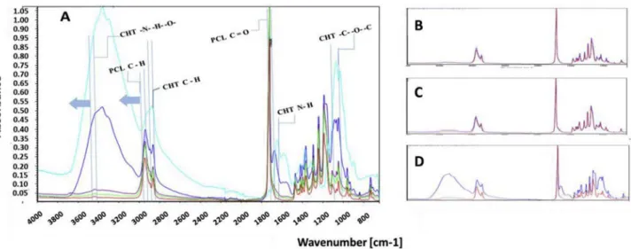
After 3 days, the well plates were taken in sterile hood and prepared for cell staining. At first the well plates were washed with PBS and the cells were fixed by adding 4% formaldehyde for 15 min. Then the wells were washed with PBS and kept in a permeabilization buffer (PB; 9:1 v:v ratio of 11 mg/ml BSA with 1% Triton X-100 in PBS) at room Fig. 4. (A) ATR-FTIR spectra of PCL/CHT scaffold on bottom surface where; PCL/CHT 100/0 in red, PCL/CHT 90/10 in green, PCL/CHT 80/20 in purple, PCL/CHT
70/30 in blue and CHT crude in cyan color respectively. (B, C & D) ATR-FTIR spectra of PCL/CHT 90/10, 80/20 & 70/30 scaffold respectively on either side of same membrane where; top surface in red and bottom surface in blue color respectively. (For interpretation of the references to color in this figure legend, the reader is referred to the Web version of this article.)
Fig. 5. Chemical mapping of PCL/CHT blends on either surface on the same membrane where; C=O for PCL observed at 1726 cm−1and hydrogen bonded N–H and
O–H observed at 3364 cm−1. Red and blue colors indicate the intensity of the corresponding bands, high and low intensity, respectively, corresponding to high and
temperature for 15 min to block any non-specific protein-binding sites. Phallodin-488 and DAPI (Actin Green 488, NucBlue, Thermo Fisher Scientific) were added together in the concentration of 1 drop/ml and 1:4000 in PB, respectively, and incubated at room temperature for 1 h. To prevent photo-bleaching, the well plates were protected from light exposure from this step onwards. Then the well plates were washed thoroughly with PBS and imaged with confocal microscopy (Zeiss LSM
510, Nikon) in 20 × and 60 × magnification (Fig. 12.). As
supple-mentary information, other biological characterizations have been performed with human mesenchymal stem cells (MSCs) in a successive
z-stack confocal analysis on these 3D scaffolds [44] and the hydraulic
permeability of HUVECs layers have been measured in a microfluidic
organ-on-chip device [44,45].
3. Results and discussion
3.1. Polymer-solvent-non solvent optimization
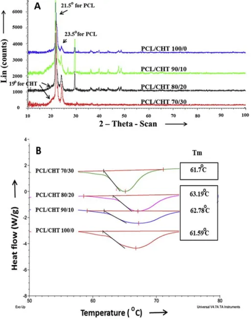
Chitosan (CHT) and polycaprolactone (PCL) are polymers with very different chemical properties and finding a common solvent to develop a membrane was an important challenge. Moreover, maintaining an Fig. 6. (A). X-ray diffraction spectra for the different blends, (B) Differential scanning calorimetric study of blends as a function of PCL content in the blend.
Fig. 7. Nishi – Wang plot. Where Tm and Tm2are the equilibrium melting
temperature (K) of the blend and pure PCL, respectively, and Ψ2is the volume
optimum viscosity was very important to achieve the double porous membrane structure. The solvent optimization have been partially
based on viscosity measurement of the polymer casted solution (Fig. 2)
as it was an important parameter that directed the size of the macro-voids during solvent exchange. During solvent mixing, a visible re-duction of the viscosity has been observed by dissolving PCL in the common solvent after 2–3 h at temperature more than 35 °C, probably due to the hydrolysis of ester bonds of PCL. In order to avoid the re-duction of viscosity, different factors were tuned. CHT was dissolved in the solvent mixture at first at 55 °C for 12 h and then PCL was added when the temperature was below 35 °C. In the common solvent, formic acid was found more responsible for the breakage of PCL ester bonds, although higher wt% of formic acid was better for faster and bead free dissolution. For these reasons, the solvent was also optimized for each PCL/CHT polymer blend according the following composition: PCL/ CHT 100/0 (15 wt%) in FA/AA 70/30 (w/w) %, PCL/CHT 90/10 and
80/20 (14 wt%) in FA/AA 60/40 (w/w) % and PCL/CHT 70/30 (10 wt
%) in FA/AA 50/50 (w/w) % (Table 1). In these conditions of
com-position and temperature, a clear, light yellow and viscous solution was obtained within 2 h. After this dissolution step, the polymer solution was kept in stand for 10–20 min before starting the membrane casting. Due to high viscosity of CHT in the solvent mixture, PCL/CHT blend beyond 70/30 ratio was not successful as it was difficult to make a homogeneous mixture of polymer solution by mechanical stirrer and to avoid phase segregation between the two polymers. Viscosity of CHT
was remarkably high in the solvent mixture (Fig. 2) that dissolving pure
CHT above 4 wt% was difficult and concentration lower than 4 wt% are not sufficient to make a double porous membrane certainly due to lack of good entanglement between the polymer chain or a phase inversion leading to polymer particles.
The viscosity of the final polymer solution of pure PCL, CHT and the
different blends were measured and reported inFig. 2. Results showed
that the viscosity of pure CHT of only 4 wt% solution was significantly higher than the viscosity of PCL/CHT 100/0 of 15 wt% solution in the common solvent. This was due to several factors. First of all, the mo-lecular weight of CHT (190 kDa–310 kDa) was higher than the mole-cular weight of PCL (80 kDa). Secondly, CHT has higher affinity to-wards the solvent due to the presence of stronger secondary interaction between the functional groups of CHT and the common solvent. As a result, CHT polymer chains likely to be deployed in the solvent leading
to higher viscosity [46]. On contrary, in acidic solvent, the viscosity of
PCL could be decreased to some extent due to a decrease of the polymer chain length via breakdown of ester linkages. All these effects are re-sponsible for the high difference of solution viscosity between these two polymers.
Concerning the non-solvent, concentration of NaOH more than 0.5 M in the non-solvent bath was responsible to make the membrane fragile by breaking the ester bonds in PCL during membrane formation. Concentration lower than 0.2 M was not sufficiently concentrated to allow the formation of macrovoids. We also varied the concentration of the NaOH solution depending upon the viscosity of the casted solution in order to get consistent macrovoids height of about 50–70% of the total membrane thickness. Finally, a 0.3 M NaOH solution was used for PCL/CHT 100/0 (15 wt%) and 0.5 M NaOH solution was used for the rest of the PCL/CHT blend.
3.2. Morphology of the double porous membrane
After the membrane fabrication, the top surface and the cross
sec-tion morphological characteristics were observed in SEM (Fig. 3). All
the scaffolds, which were produced by using the track-etched mem-brane, are showing double porosity where the macrovoids are open towards the top surface and connected with the spongy microporous network. From the cross section view, it was observed that the localized arrival of the non-solvent inside the polymer solution were creating the macrovoids which were increasing by increasing CHT wt.%. The mac-rovoids diameter were around 20 ± 3–90 ± 5 μm and the diameter of interconnected micropores were around 7 ± 3 μm (except the PCL/ CHT 70/30 ratio for which the micropore diameter was 20 ± 5 μm (Table 1)).
3.3. Chemical characterization by ATR-FTIR spectra
The representative FTIR spectra of the bottom surface of the
mem-brane are shown inFig. 4 (A). All the stretching and bending vibrations
are found to be well matching with the reported values [31]. In crude
CHT, the broad peak at 3364 cm−1 was found due to stretching
vi-bration of intramolecular hydrogen bonding between N–H and O–H.
The peak at 2880 cm−1was due to the asymmetric bending of C–H
group. The N–H and C–O–C peaks were observed at 1651 cm−1and
1070 cm−1 respectively. In PCL, the peaks at 2946 cm−1 and
1726 cm−1 represent the characteristic peaks for C–H and ester
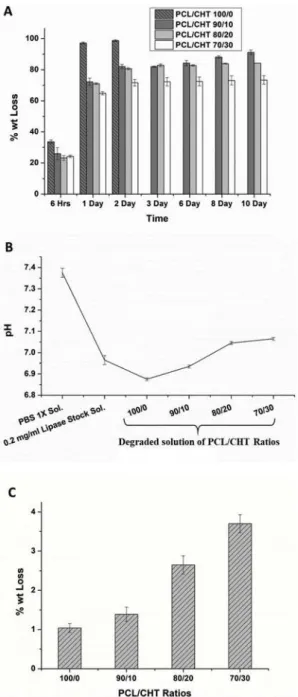
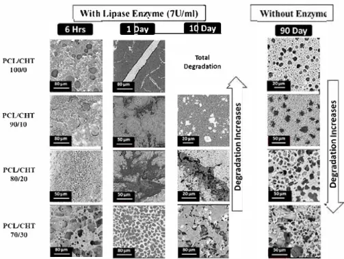
Fig. 8. (A) Weight loss % of the sample with lipase enzyme (Pseudomonas ce-pacia; 7 U/ml) at different time intervals, (B) pH of the enzyme degraded
so-lution after the study and (C) weight loss % of the sample without enzyme after 90 days.
With Lipase Enzyme (7U/ml) 1
ll•NI iujtfi
PCUCIJT 100/0 PCUCHT 90/10 PCUCHT 80/20 PCUCHT 70/30 Total Degradation "' QI "' "' QI...
u C: 0 .:; "' "C QI 0Fig. 9. SEM images of degraded PCL/CHT blends after 6 h, 1 day and 10 days with lipase enzyme (Pseudomonas cepacia; 7 Ulm!) and after 90 days without enzyme. carbonyl (C=O) groups respectively. In PCL/CHT blend, by decreasing
CHT proportion, the stretching vibration of intramolecular hydrogen bonding between N-H and 0-H, shifted towards higher wavenurnber region from 3364 cm - l in PCL/CHT 70/30 to 3437 cm - l in PCL/CHT 90/10. In addition, the C-H stretching of PCL shifted also towards higher wavenurnber region from 2943 cm -l in PCL/CHT 70/30 to 2946 cm -l in PCL/CHT 90/1 O. From ail these results, no additional peak was observed indicating presence of no covalent bonding between the two polymers occurred. However, it is clear that the characteristic peak of the blend membrane were constantly shifting by changing the composition likely due to the secondary interaction between the func tional groups of two polymers [20,47]. These interactions indicate no phase separation occurs between CHT and PCL in accordance with Sarasam et al. [34] and She et al. [38] who observed a negative Flory Huggins parameter for these two polymers.
The penetration depth of AIB-FTIR absorption, dp, for a sample is
given by the following equation [31]:
À
dp=---;:::===
21r �sin2
0 - "21
(4)where, À. and 0 are the wavelength and incident angle (30') respec tively. Oit is the ratio of refractive index of the sample to that of prism. The refractive indices of germanium and polymeric materials are 4.0 and = 1.5, [31], respectively. By putting the wavenurnbers corre sponding to the characteristic absorption, we obtain a penetration depth around = 3 µm, which means that the AIB-FTIR spectra could only gather the information from first few micrometer depth of the surface, whereas the thickness of the membrane sample were around 80µm.
The comparison of AIB-FTIR spectra for either side of the same blend membrane is presented in Fig. 4(B and C, D). One can note that the intensities of specific bands of PCL and CHT are almost the same on the both surface of PCL/CHT 90/10 and PCL/CHT 80/20 membrane indicating almost homogeneous blend. Whereas, in the case of PCL/ CHT 70/30, the CHT characteristic peak were higher on the bottom surface indicating probable phase segregation of PCL and CHT through the membrane thickness. From this AIB-FTIR study, one can conclude no phase separation occurs due to the interaction between PCL and CHT but a segregation could occur through the membrane thickness from the
composition of PCL/CHT 70/30 due to distinguished chemical prop erties of the polymer mentioned earlier.
AIB-FTIR chemical mapping (Fig. 5) of two characteristic bands were observed to highlight the difference of the membrane surface chemistry; C=O (1726 cm-1) for PCL and intramolecular hydrogen bonded N-H and 0-H (3364cm-1) for CHT [21].
From the chemical FTIR mapping, on top and bottom surface, we can verify tl!at by increasing the concentration of CHT in the blends, the absorbance of C = 0 decreases and the absorbance of intramolecular hydrogen bonded N-H and 0-H increases [21,48]. In well agreement with the Fig. 4 (B, C, D), when the intensities are correlated on both the surfaces of the blend, it appears that PCL and CHT have almost the same intensities on PCL/CHT 90/0 and 80/20 indicating no macroscopic phase separation. Whereas, for the blend PCL/CHT 70/30, CHT wt% likely to be higher on the bottom surface than the top surface. More over, on the bottom surface of PCL/CHT 70/30, the local concentra tions of PCL and CHT at the micrometer scale (i.e. each pixel represents a 50 µm x 50 µm of analyzed surface) is seemingly not homogenous as CHT zone are complementary of those of PCL indicating a segregation of both polymers [34,38,49].
3.4. Qystalline and thermal properties
Crystalline properties of the blend were measured on a 1 cm2 dried
fiat sheet membrane and depicted in Fig. 6 (A). As an amorphous polymer, characteristic broad peak of CHT was hardly observed at 19' in PCL/CHT 80/20 and PCL/CHT 70/30. Characteristic intense peaks at 21.5' and 23.5' at Bragg angles 2-theta corresponding to the (1 1 O) and (2 0 O) planes in PCL can be observed. Moreover, by increasing CHT wt.
%, a slight increase of Bragg angles of the characteristic peak of PCL
was also observed, indicating an interaction with CHT in agreement with the FTIR data [31,50,51]. It could be interesting to correlate this data with Honma et al. [31], where the differences in the inter-planar spacing of (1 1 O) planes with promoting CHT, the b axes of the PCL orthorhombic cell getting more spread out in the cell. Whereas, no difference was found in the spaces of the (2 0 O) planes. From these results, it can be concluded tl!at significant molecular interaction occurs between PCL and CHT during solvent mixing which is quite contra dictory when the blend was produced by melt blending as reported
= T T R H V V 1 1 (1 ) m m u u u 2 2 2 1 12 2 2 (5) where, subscripts 1 and 2 correspond to CHT and PCL polymer,
re-spectively. To
mand Tom2are the equilibrium melting temperature (K)
of the blend and pure PCL (333.15 K) respectively. R is the universal gas
constant (1.98 cal/mol K), ΔH2uis the heat of fusion per mole of 100%
crystalline PCL (3694.67 cal/mol), V2u (99.65 cm3/mol) and V1u
(1546.82 cm3/mol) are molar volumes of the repeating unit of polymers
and Ψ2refers to the volume fraction of PCL in the blend.
The Nishi-Wang plot (Fig. 7) shows that our experimental data
cannot be represented with a line passing through the origin, indicating
that the interaction parameter (χ12) was composition-dependent and
cannot be a constant value [34]. From where it could be concluded that
like the most cases, in our data, the interaction parameter χ12was not
playing a decisive role on the melting behaviour of the crystalline-amorphous polymer systems due to elevation of melting point. This was
termed as ‘experimental verification’ reported by Nishi et al. [58].
3.5. Enzymatic degradation
The enzymatic hydrolysis of polymeric biomaterials is a hetero-geneous process that is affected by the mode of interaction between the enzymes and polymer chains. It generally involves four steps: (a) dif-fusion of the enzyme from the bulk solution to the solid surface, (b) adsorption of the enzyme on the substrate, forming an zyme–substrate complex, (c) hydrolysis reaction catalyzed by the en-zyme, forming smaller, soluble polymeric chain and (d) diffusion of the soluble degradation products from the solid substrate to the solution
[29]. The rate of the overall degradation is controlled by the slowest
step. The effect of enzymatic degradation by lipase in terms of wt. loss
(%) was observed on four batches of samples inFig. 8 (A). A fast and
almost selective degradation of PCL from all the blends within 48 h was found. This was because the concentration of lipase (7 U/ml) in the
experiment was higher than the human physiological condition
(0.03–0.190 U/ml) [59–61]. In addition, the enzyme can easily diffuse
through the bulk of porous scaffolds as the size of the bulky protein chains of the enzymes (> 10 nm) is more than 100 times smaller than the scaffolds pore size, leading to a faster degradation compared to dense, non-porous scaffolds.
Contrastingly, when the degradation was conducted without
en-zyme, the degradation of the blend was significantly low (Fig. 8 (C))
[17]. Moreover, Pure PCL showed the lowest degradation and the
de-gradation increases by increasing the CHT wt.%.
The mechanisms leading to the degradation of the PCL and CHT polymers are significantly different. Generally, PCL, like polyester, degrades similarly to lipid hydrolysis, which is highly facilitated by lipase (lipidase) like enzyme. Lipases are water-soluble enzymes that hydrolyze ester bonds of water-soluble substrates such as triglycerides,
phospholipids, and cholesteryl esters [62]. Increasing the CHT wt.% (or
decreasing PCL wt.%) not only increases the hydrophilicity but also increases the macrovoids size. As a result the porous bulk of scaffolds was more accessible by the enzymatic solution leading to faster de-gradation via formation of a smaller soluble enzyme–substrate complex
[63]. On the other hand, CHT, like polysaccharide, consisting of
N-acetyl/deacetyl glucosamine, degrades by oxidative-reductive chain
scission and lipase has very weak effect on CHT degradation [64–67]. In
case of degradation without enzyme, the ability of the material to swell
by absorbing water [68], which was increasing by increasing CHT wt.
%, plays a key role for the degradation.
The surface morphology of degraded membrane after different time
intervals is presented in theFig. 9. In case of degradation assay with
enzyme, a noticeable damage on the surface of membranes were ob-served with a significant weight loss.
The change in pH measured in the degraded solution is reported in theFig. 8 (B). PCL/CHT 100/0 has shown the lowest pH probably due to the presence of higher amount of acidic residue via ester chain de-gradation. Overall in all the blends, the pH remained very close to the physiological pH (7.4), indicating almost no toxicity of the degraded solution.
3.6. Microscopic PCL/CHT chemical structure
The presence of secondary interactions between PCL and CHT was observed above in the FTIR as well as in the crystallinity (with a shift of the characteristic peaks) that allow avoiding phase separation and total immiscibility between the two polymers.
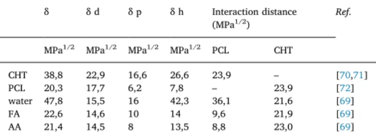
The solvent and non-solvent power can be evaluated through the interaction distances using the Hansen solubility parameter approach
[69]. From theTable 2, the interaction distances are found lowest
be-tween PCL and the acids (FA/AA), indicating the acids are good sol-vents for PCL whereas water is a non-solvent with highest interaction distance. On the other hand, the interaction distances between CHT and the acids (FA/AA) was found high (with almost the same non-solvent power), indicating the acids are not good solvent for CHT. However, the solubility of CHT in water at low pH as well as in concentrated acids is usually observed due to strong acid/base interaction, turning CHT to a polyelectrolyte via protonation of amine groups. The use of NaOH so-lution as a non-solvent is then crucial, as the base will deprotonate the amine groups leading to insoluble CHT. Thus, NaOH solution is a stronger non-solvent of CHT than pure water.
Thus the phase segregation phenomena along the membrane thickness with high CHT wt% (apparently in PCL/CHT 70/30 in our
case) can be explained (Fig. 10.) by the presence of a NaOH conc.
gradient along the thickness of the polymer solution (i.e. high NaOH conc. at the top to low NaOH conc. at the bottom) during the phase inversion process. The NaOH conc. gradient was created along the thickness of the polymer solution due to faster neutralization at the top surface than at the bottom surface, leading to the formation of
con-jugate bases (FA−and AA−, which are non-solvent too). The presence
earlier [52]. It was also reported that by increasing the CHT wt%, the
intensity of the characteristic peak of PCL should decrease as the con-jugation with PCL and CHT chains suppresses the crystallization of PCL [31,53–55]. Unlike the other reported data, in our case, this effect was not observed and we found a considerable increase of intensity of the PCL specific peak in the blend by increasing CHT wt.%.
Apart from the characteristic peaks of PCL and CHT, some other intense peaks were also detected due to the formation of different type
of crystals with different D spacing within the crystal lattice [51]. Those
gave an overall crystalline behaviour to the blend. Although in case of PCL/CHT 70/30, those peaks were almost disappear due to significant amorphousness induced by CHT.
DSC analysis Fig. 6 (B) were also performed on the same batch of
the sample. Generally, higher a polymer material will have crystallinity, higher energy should be required to break the crystal, hence higher will
be the temperature of melting (Tm). In our case by increasing CHT wt%
the temperature of melting (Tm) of the blend was increasing whereas in
case of PCL/CHT 70/30 it was decreasing. This phenomena can be
correlated with the crystallinity of the blend as discussed above [21].
Generally, pure PCL melts at 60 °C, whereas CHT undergoes thermal
degradation at around 270 °C prior to melting [21]. It is still difficult to
determine the glass transition (Tg) of CHT by conventional thermal
technique, although some efforts have been done [52,56,57]. Thus, the
variation of the melting point of PCL in the blend was monitored by varying the composition of CHT. Unlike other reported data
[21,31,32,35], we found that by increasing CHT wt%, Tm of the blend
increased [51] except PCL/CHT 70/30.
The interaction between the two polymers can be analyzed through
the Flory-Huggins interaction parameter (χ12) to correlate temperature
of melting and volume fraction of PCL. The equation is evaluated from
the simplified Nishi-Wang equation [34,58] for high MW
crystalline-amorphous polymer system as follows:
of conjugate bases increased the gradient of solvent activity. CHT chains have more affinity for the solvent (FA/AA) than PCL and thus the gradient of chemical potential for CHT is more important than PCL
[73]. Due to these differences in chemical potential gradient, CHT
should move towards the bottom surface to some extent higher than PCL chains. Whereas PCL chains coagulated on the top surface faster than CHT as water is a strong non solvent of PCL. The PCL chains will be trapped in contact with water and cannot move anymore.
3.7. Mesoscopic morphological structuration of the membrane
The equilibrium phase diagram for the ternary system of
polymer-solvent-nonsolvent,Fig. 11 (A), can be used to understand the route
taken during the membrane precipitation process, leading to the for-mation of double porosity. Any point within the triangle represents a mixture of three components where the system composed of two phases: a one-phase region, where all components are miscible, and a two-phase region, where the system separates into high viscosity (polymer-rich) and low viscosity (polymer-poor) phases. The liquid-li-quid phase boundary is the so-called binodal curve. Every composition inside the binodal curve will demix into two liquid phases which differ in composition but are thermodynamically in equilibrium with each other. The tie line connects a pair of equilibrium compositions in the phase diagram. Thus, at low polymer concentrations where the tie line intersects the binodal, the system is a low viscosity polymer-poor phase. As the concentration of polymer is increased, the viscosity of the system also increases rapidly and the tie line intersects the binodal at high polymer concentration, consider as the gelation point (E), a highly viscous polymer-rich phase that further polymer chain movement is not
possible [74,75].
Two extreme cases can be considered according to the PCL/CHT
percentage ratio: Case 1 (left column in Fig. 11.) corresponds to the
pure PCL blend and case 2 (right column inFig. 11.) corresponds to the
PCL/CHT blend with lower polymer percentage. As previously dis-cussed, one difference between these cases is the use of higher NaOH solution in the non-solvent phase for higher CHT concentration. In the last case, the gelation point should occur for higher polymer con-centration, as there is less attractive interaction between CHT and solvent in basic solution.
Regarding the triangular phase diagram (Fig. 11 (A)), the entire
membrane formation process follows the path (A-B-C-D), where A re-presents the initial casted solution when it is just immersed inside the non-solvent (t = 0), B represents the demixing point where the two liquid phases formation start. As the two-phase formation proceed, more solvent was neutralized by increasing the viscosity of the polymer-rich phase. At one point, the viscosity is high enough to restrict further polymer chain movement and the polymer is considered as solid, representing the solidification point C, where it intersects the tie line with the gelation point E. From B to C, the polymer lean phase coalesces to form the observed macrovoid: the extent of the coalescence depends of the time need to go from B to C.
After that, the membrane structure does not evolve and further solvent exchange results in the removal of solvent. Some shrinkage of the bulk volume could also occurs leading to the final membrane
structure D [74,76]. The composition D is in equilibrium between the
polymer-rich and polymer-poor phase and the position of point D on the polymer/non-solvent line of the phase diagram determines the overall porosity of the membrane.
Due to the presence of the track-etched membrane on the casted solution, just after immersion, the non-solvent has a restricted access to the polymer solution through the pore of the track-etched membrane, initiating a spatially heterogeneous solvent-nonsolvent exchange
[30,77]. The phase inversion starts in the zone where there is a direct
contact between the polymer and the non-solvent, resulting the initia-tion and growth of a liquid wall (nascent macrovoids). The liquid wall, created from the phase inversion, expands radially from the non-solvent invasion point (polymer-poor phase) towards the bulk (polymer-rich phase). During the phase inversion, the polymer concentration of the liquid wall increases until the solidification point C and thus further
polymer chain movement stops [74,76].
The polymer blend composition, polymer wt.% and non-solvent concentration play an influential role on the macrovoid size and on the membrane porosity. Particularly in the case 2, where CHT is present along with PCL inside the polymer solution, the blend has a higher affinity with solvents than PCL alone. This is due to higher secondary interaction between the CHT functional groups and solvents, higher M.W and the presence of cyclic structure, resulting deployment and
high entanglement of CHT chains in the solution [40]. In that case and
after the demixing point, the non-solvent first has to disable those
δ δ d δ p δ h Interaction distance
(MPa1/2) Ref.
MPa1/2 MPa1/2 MPa1/2 MPa1/2 PCL CHT
CHT 38,8 22,9 16,6 26,6 23,9 – [70,71]
PCL 20,3 17,7 6,2 7,8 – 23,9 [72]
water 47,8 15,5 16 42,3 36,1 21,6 [69]
FA 22,6 14,6 10 14 9,6 21,9 [69]
AA 21,4 14,5 8 13,5 8,8 23,0 [69]
Fig. 10. Qualitative representation of
the gradient along the thickness and the differential migration of PCL (in blue) and CHT (in red) in the blend after phase inversion (where PCL is polycaprolactone, CHT is chitosan, FA is formic acid, AA is acetic acid, FA−is
formate anion and AA−acetate anion
respectively). (For interpretation of the references to color in this figure legend, the reader is referred to the Web ver-sion of this article.)
Table 2
Hansen solubility parameter of CHT, PCL and solvents and the interaction distance. All values are given in MPa1/2.
secondary interaction between CHT and solvents followed by solvent exchange via acid-base reaction, leading to a delay in solidification
(t = t2, path B–C). Meantime, more non-solvent invades due to a higher
non-solvent concentration and lower polymer wt.% (in the case of PCL/ CHT 70/30 with 10 wt%). As a results further expansion of the liquid wall take place and eventually two neighboring nascent liquid walls coalesce before reaching the solidification point C, leading to the
for-mation of larger macrovoids [74,76]. In case 1, due to the presence of
PCL alone, after the demixing point, the solvent exchange starts readily as, unlike CHT, PCL does not have strong affinity with the solvents. In addition, due to the lower nonsolvent concentration and higher polymer wt.% (PCL/CHT 100/0 with 15 wt%), the liquid wall reaches
the solidification point C (t = t1; where t1< t2) before significant
ex-pansion, resulting in smaller macrovoids.
A secondary solvent exchange followed by phase inversion also occurs through the whole volume of the polymer solution because of the slow diffusion of the non-solvent through the newly formed mac-rovoids. The polymer solution area, which is protected from direct exposure from the non-solvent due to the presence of the track-etched membrane, undergoes the secondary solvent exchange. This phase in-version takes place at a slower rate and leads to the formation of a uniform spongy microporous network connected by the macrovoids
[30,74,76,77].
Remigy et al. [76] and, earlier, Strathmann et al. [74] reported that,
due to the heterogeneous and restricted solvent diffusion, the genera-tion of macrovoid can also be achieved by a dense skin formagenera-tion on the polymer solution layer via rapid homogeneous precipitation. In that
case, after formation of the dense skin, it disrupts by shrinkage of the homogeneous solid layer and the macrovoid formation starts from the disruption point due to the heterogeneous and restricted access of the non-solvent. In the present work, we cover the polymer solution with track-etched membrane, which acts as a dense skin with restricted
ac-cess of the non-solvent [30,77]. The use of track-etched membrane and
its removal allows the generation of largely open macrovoids, which were not obtained using the classical phase inversion technique. When no track-etched membrane was used, the membrane material presented single porosity like conventional liquid-liquid homogeneous phase in-version and pores were not open enough towards the top surface (Fig. 3. I, J).
3.8. Cellular compatibility study by LSCM
The cellular compatibility of the four batch of membranes were
observed in confocal images (Fig. 12) at 20× and 60× magnification
after 3 days of seeding HUVECs. The cell nucleus were stained by DAPI in blue and the actin stress fibers were stained by Phalloidin Alexa Fluor™ 488 in green. The scaffolds were designed to develop as bioac-tive scaffolds for a tissue engineered vascular grafts to obtain higher endothelial performance by the HUVECs by tuning the physico-che-mical and morphological properties of the blends. At 20× magnifica-tion all the membranes are showing a very high number of cells adhered on the membrane. By introducing CHT, all the PCL/CHT blend are showing even higher number of cell-cell and cell-scaffolds interaction than only pure PCL membrane and make an almost confluent Fig. 11. (A). Schematic phase diagram of the system polymer-solvent-nonsolvent representing the membrane macrovoids formation pathway (A-B-C-D), (B).
Illustrative representation of the formation of macrovoids. Case 1: formation of smaller macrovoids consisting of polymer as PCL, solvent as FA/AA and non-solvent as NaOH at low concentration and Case 2: formation of bigger macrovoids consisting of polymer as PCL + CHT, solvent as FA/AA and non-solvent as NaOH at high concentration (where PCL is polycaprolactone, CHT is chitosan, FA is formic acid, AA is acetic acid respectively).
monolayer within 3 days. In 60× magnification, we discover that the HUVECs maintain their natural endothelial like morphology by strongly expressing the actin fibers in green, which was significantly visible in PCL/CHT 80/20 and 70/30 blend. These findings clearly suggest that all four batches of scaffolds are highly biocompatible, especially by introducing CHT, likely because of better hydrophilicity, pore spacing
and morphology. Du et al. [22] reported rapid HUVECs adhesion and
proliferation upon gradient PCL/CHT nanofibrous, electrospun scaf-folds than the uniform one due to higher adsorption of VEGF on the
CHT rich side (luminal side). Casillo et al. [78] grew endothelial cells
on non-porous and porous SiO2membranes where they find higher
cell-matrix adhesion on the surface with bigger pores probably because the spacing between the pores, and thus the amount of continuous space for the cells to adhere was higher.
The exclusive cellular characterization of these double porous ma-terials was extensively carried out and already reported in previous
papers [44,45]. Static cell culture with human mesenchymal stem cells
(hMSCs) has been performed for 3 weeks. With confocal images, it was shown that these materials have a good ability to promote cellular
in-vasion and proliferation by increasing CHT wt% [44]. The additional
cellular resistance has also been monitored by seeding human umbilical vein endothelial cells (HUVECs) on the membranes embedded inside a
microfluidic organ-on-chip system by mimicking dynamic physiological condition. Here again the results suggest that by increasing CHT wt%, the microstructural and chemical properties were significantly im-proved resulting in enhanced hydraulic resistance due to increased
cellular barrier function [45].
Significant advancement has been made in engineered blood vessels grafts with development of bioscaffolds constructs, providing an alter-native to replace the damaged vessel in treating cardiovascular diseases (CVD). The successful implementation of these two kind of cells in our studies could be strategically useful to regenerate small diameter blood vascular system. Human endothelial cells (ECs) can be seeded on the surface of the 3D scaffold (on the luminal side). Whereas seeding the mesenchymal stem cells (MSCs) inside the bulk could be obvious due to two beneficial properties. MSCs could be genetically modified to pro-duce the essential vascular endothelial growth factors (VEGFs) in order
to enhance the endothelium [79–81], which is very important, as the
damaged endothelium could not produce the VEGFs naturally [82].
MSCs proliferation and viability are highly dependent on environ-mental cues like material stiffness, growth medium and other physical
and mechanical forces [83,84]. With proper environmental condition,
MSCs can change their phenotype to smooth muscle cells, which are
usually present inside the vessels underneath the endothelium [85–87].
As the cell will grow, the biodegradable scaffold will be gradually re-placed by cells and, at the end, the scaffold will be completely absorbed inside the body to achieve the blood vessel construct.
4. Conclusions
A PCL/CHT membrane with a unique double porosity level has been developed for tissue engineering applications. The membrane has been fabricated with a modified phase inversion technique from different ratios of PCL/CHT polymer blends. Macrovoids at the membrane sur-face have been formed which are connected through membrane mi-croporous network. The physico-chemical properties and morpholo-gical structure of the membrane have been characterized and the mechanisms at the origin of the membrane formation have been dis-cussed. This membrane exhibits interesting functionalities for tissue engineering applications:
- The membrane possesses a structure with three dimensional double porosity level, thanks to the micro-patterning techniques. The SEM images show that plenty of micrometers macrovoids (20–90 μm) are connected through spongy porous network.
- The morphological analysis of the membrane shows that the mac-rovoids size increased by increasing the Chitosan concentration. ATR-FTIR chemical spectra confirm the presence of secondary in-teraction between PCL and Chitosan. From the FTIR chemical mapping, we found a slight segregation of polymers along the thickness in case of high Chitosan wt.%. From the XRD and DSC studies, we observed an increase of the crystallinity and melting point by increasing CHT wt.%.
- The biodegradability of the material can be adjusted according to the PCL/CHT ratio. The enzymatic degradation of the PCL/CHT double porous scaffold using lipase (from P. cepacia), pointed out a faster and almost selective degradation of PCL in the blend. - Human umbilical vein endothelial cells (HUVECs) show rapid cell
adhesion and proliferation on the membranes, especially by in-troducing chitosan in the blend, by maintaining their natural cel-lular morphology. PCL/CHT materials allows then to act as a niche to host cells. Such a structure could ensure biofunctionality for tissue repair: where the macrovoids could be useful for three-di-mensional cell culture and spongy microporous network could be useful to transport essential nutrients, growth factors and oxygen for cell survival.
The encouraging data obtained in this work demonstrate that these Fig. 12. LSCM images of HUVECs on PCL/CHT membrane after 3 days with
staining (nucleus by DAPI in blue and cell cytoskeleton by phalloidin in green). Scale bar: 100 μm in 15 × mag. and 50 μm 60 × mag. respectively. (For in-terpretation of the references to color in this figure legend, the reader is referred to the Web version of this article.)
[1] S.J. Hollister, Porous scaffold design for tissue engineering, Nat. Mater. 4 (2005) 518,https://doi.org/10.1038/nmat1421.
[2] M.M. Stevens, J.H. George, Exploring and engineering the cell surface interface, Science 310 (2005) 1135–1138,https://doi.org/10.1126/science.1106587. [3] I. Manavitehrani, A. Fathi, H. Badr, S. Daly, A. Negahi Shirazi, F. Dehghani,
Biomedical applications of biodegradable polyesters, Polymers 8 (2016) 20,
https://doi.org/10.3390/polym8010020.
[4] V.D. Palumbo, A. Bruno, G. Tomasello, G. Damiano, L. Monte, A.I., Bioengineered vascular scaffolds: the state of the art, Int. J. Artif. Organs 37 (2014) 503–512,
https://doi.org/10.5301/ijao.5000343.
[5] B.P. Tripathi, P. Das, F. Simon, M. Stamm, Ultralow fouling membranes by surface modification with functional polydopamine, Eur. Polym. J. 99 (2018) 80–89,
https://doi.org/10.1016/j.eurpolymj.2017.12.006.
[6] Yumei Xiao, Dongxiao Li, Xuening Chen, Jian Lu, Hongsong Fan, Xingdong Zhang, Preparation and cytocompatibility of chitosan‐modified polylactide, J. Appl. Polym. Sci. 110 (2008) 408–412,https://doi.org/10.1002/app.28493.
[7] R.S. Teotia, D. Kalita, A.K. Singh, S.K. Verma, S.S. Kadam, J.R. Bellare, Bifunctional polysulfone-chitosan composite hollow fiber membrane for bioartificial liver, ACS Biomater. Sci. Eng. 1 (2015) 372–381,https://doi.org/10.1021/ab500061j. [8] M. Prabaharan, M.A. Rodriguez-Perez, J.A. de Saja, J.F. Mano, Preparation and
characterization of poly(L-lactic acid)-chitosan hybrid scaffolds with drug release capability, J. Biomed. Mater. Res. B Appl. Biomater. 81B (2007) 427–434,https:// doi.org/10.1002/jbm.b.30680.
[9] F. Chen, X. Li, X. Mo, C. He, H. Wang, Y. Ikada, Electrospun chitosan-P(LLA-CL) nanofibers for biomimetic extracellular matrix, J. Biomater. Sci. Polym. Ed. 19 (2008) 677–691,https://doi.org/10.1163/156856208784089661.
[10] A. Di Martino, M. Sittinger, M.V. Risbud, Chitosan: a versatile biopolymer for or-thopaedic tissue-engineering, Biomaterials 26 (2005) 5983–5990,https://doi.org/ 10.1016/j.biomaterials.2005.03.016.
[11] X. Zhou, M. Kong, X.J. Cheng, C. Feng, J. Li, J.J. Li, X.G. Chen, In vitro and in vivo evaluation of chitosan microspheres with different deacetylation degree as potential embolic agent, Carbohydr. Polym. 113 (2014) 304–313,https://doi.org/10.1016/j. carbpol.2014.06.080.
[12] S. Hong, G. Kim, Fabrication of electrospun polycaprolactone biocomposites re-inforced with chitosan for the proliferation of mesenchymal stem cells, Carbohydr. Polym. 83 (2011) 940–946,https://doi.org/10.1016/j.carbpol.2010.09.002. [13] Q.F. Dang, S.H. Zou, X.G. Chen, C.S. Liu, J.J. Li, X. Zhou, Y. Liu, X.J. Cheng,
Characterizations of chitosan-based highly porous hydrogel—the effects of the solvent, J. Appl. Polym. Sci. 125 (2012) E88–E98,https://doi.org/10.1002/app. 36681.
[14] X. Zhou, X.J. Cheng, W.F. Liu, J. Li, L.H. Ren, Q.F. Dang, C. Feng, X.G. Chen, Optimization and characteristics of preparing chitosan microspheres using response surface methodology, J. Appl. Polym. Sci. 127 (2013) 4433–4439,https://doi.org/ 10.1002/app.38003.
[15] X. Zhou, M. Kong, X. Cheng, J. Li, J. Li, X. Chen, Investigation of acetylated chitosan microspheres as potential chemoembolic agents, Colloids Surfaces B Biointerfaces 123 (2014) 387–394,https://doi.org/10.1016/j.colsurfb.2014.07.044. [16] Q.Q. Wang, M. Kong, Y. An, Y. Liu, J.J. Li, X. Zhou, C. Feng, J. Li, S.Y. Jiang,
X.J. Cheng, X.G. Chen, Hydroxybutyl chitosan thermo-sensitive hydrogel: a po-tential drug delivery system, J. Mater. Sci. 48 (2013) 5614–5623,https://doi.org/ 10.1007/s10853-013-7356-z.
[17] Ana R. Costa-Pinto, Ana M. Martins, Magda J. Castelhano-Carlos, Vitor M. Correlo, Paula C. Sol, Adhemar Longatto-Filho, Mrinal Battacharya, Rui L. Reis, Nuno M. Neves, In vitro degradation and in vivo biocompatibility of chitosan–poly
[18] W.F. Liu, H.D. Zang, X. Zhou, C.Z. Kang, Y. Li, J. Li, Q.F. Dang, X.J. Cheng, X.G. Chen, The primary culture and subculture of lymphoid cells from shrimp, Penaeus chinensis on thermo-sensitive CS/α, β-GP hydrogel, Aquacult. Res. 45 (2014) 334–340,https://doi.org/10.1111/j.1365-2109.2012.03231.x.
[19] A. Cooper, N. Bhattarai, M. Zhang, Fabrication and cellular compatibility of aligned chitosan–PCL fibers for nerve tissue regeneration, Carbohydr. Polym. 85 (2011) 149–156,https://doi.org/10.1016/j.carbpol.2011.02.008.
[20] V.N. Malheiro, S.G. Caridade, N.M. Alves, J.F. Mano, New poly(ε-caprolactone)/ chitosan blend fibers for tissue engineering applications, Acta Biomater. 6 (2010) 418–428,https://doi.org/10.1016/j.actbio.2009.07.012.
[21] D.M. García Cruz, J.L. Gomez Ribelles, M. Salmerón Sánchez, Blending poly-saccharides with biodegradable polymers. I. Properties of chitosan/poly-caprolactone blends, J. Biomed. Mater. Res. B Appl. Biomater. 85 (2008) 303–313,
https://doi.org/10.1002/jbm.b.30947.
[22] F. Du, H. Wang, W. Zhao, D. Li, D. Kong, J. Yang, Y. Zhang, Gradient nanofibrous chitosan/poly ɛ-caprolactone scaffolds as extracellular microenvironments for vascular tissue engineering, Biomaterials 33 (2012) 762–770,https://doi.org/10. 1016/j.biomaterials.2011.10.037.
[23] Y. Yao, J. Wang, Y. Cui, R. Xu, Z. Wang, J. Zhang, K. Wang, Y. Li, Q. Zhao, D. Kong, Effect of sustained heparin release from PCL/chitosan hybrid small-diameter vas-cular grafts on anti-thrombogenic property and endothelialization, Acta Biomater. 10 (2014) 2739–2749,https://doi.org/10.1016/j.actbio.2014.02.042.
[24] A. Cooper, N. Bhattarai, F.M. Kievit, M. Rossol, M. Zhang, Electrospinning of chitosan derivative nanofibers with structural stability in an aqueous environment, Phys. Chem. Chem. Phys. 13 (2011) 9969–9972,https://doi.org/10.1039/ C0CP02909B.
[25] T. Honma, T. Senda, Y. Inoue, Thermal properties and crystallization behaviour of blends of poly(ε-caprolactone) with chitin and chitosan, Polym. Int. 52 (2003) 1839–1846,https://doi.org/10.1002/pi.1380.
[26] S.D. Vrieze, P. Westbroek, T.V. Camp, L.V. Langenhove, Electrospinning of chitosan nanofibrous structures: feasibility study, J. Mater. Sci. 42 (2007) 8029–8034,
https://doi.org/10.1007/s10853-006-1485-6.
[27] R. Jayakumar, M. Prabaharan, S.V. Nair, H. Tamura, Novel chitin and chitosan nanofibers in biomedical applications, Biotechnol, Adv 28 (2010) 142–150,https:// doi.org/10.1016/j.biotechadv.2009.11.001.
[28] L. Wu, H. Li, S. Li, X. Li, X. Yuan, X. Li, Y. Zhang, Composite fibrous membranes of PLGA and chitosan prepared by coelectrospinning and coaxial electrospinning, J. Biomed. Mater. Res. A. 92 (2010) 563–574,https://doi.org/10.1002/jbm.a.32393. [29] M. Rahmouni, F. Chouinard, F. Nekka, V. Lenaerts, J.C. Leroux, Enzymatic
de-gradation of cross-linked high amylose starch tablets and its effect on in vitro re-lease of sodium diclofenac, Eur. J. Pharm. Biopharm. 51 (2001) 191–198,https:// doi.org/10.1016/S0939-6411(01)00127-8.
[30] M. Dufresne, P. Bacchin, G. Cerino, J.C. Remigy, G.N. Adrianus, P. Aimar, C. Legallais, Human hepatic cell behavior on polysulfone membrane with double porosity level, J. Membr. Sci. 428 (2013) 454–461,https://doi.org/10.1016/j. memsci.2012.10.041.
[31] T. Honma, L. Zhao, N. Asakawa, Y. Inoue, Poly(ε-Caprolactone)/Chitin and poly(ε-caprolactone)/chitosan blend films with compositional gradients: fabrication and their biodegradability, Macromol. Biosci. 6 (2006) 241–249,https://doi.org/10. 1002/mabi.200500216.
[32] K.T. Shalumon, K.H. Anulekha, C.M. Girish, R. Prasanth, S.V. Nair, R. Jayakumar, Single step electrospinning of chitosan/poly(caprolactone) nanofibers using formic acid/acetone solvent mixture, Carbohydr. Polym. 80 (2010) 413–419,https://doi. org/10.1016/j.carbpol.2009.11.039.
[33] I. Olabarrieta, D. Forsström, U.W. Gedde, M.S. Hedenqvist, Transport properties of chitosan and whey blended with poly(ε-caprolactone) assessed by standard per-meability measurements and microcalorimetry, Polymer 42 (2001) 4401–4408,
https://doi.org/10.1016/S0032-3861(00)00680-7.
[34] A. Sarasam, S.V. Madihally, Characterization of chitosan–polycaprolactone blends for tissue engineering applications, Biomaterials 26 (2005) 5500–5508,https://doi. org/10.1016/j.biomaterials.2005.01.071.
[35] A.R. Sarasam, P. Brown, S.S. Khajotia, J.J. Dmytryk, S.V. Madihally, Antibacterial activity of chitosan-based matrices on oral pathogens, J. Mater. Sci. Mater. Med. 19 (2008) 1083–1090,https://doi.org/10.1007/s10856-007-3072-z.
[36] A.R. Sarasam, R.K. Krishnaswamy, S.V. Madihally, Blending chitosan with Polycaprolactone: effects on physicochemical and antibacterial properties, Biomacromolecules 7 (2006) 1131–1138,https://doi.org/10.1021/bm050935d. [37] A.R. Sarasam, A.I. Samli, L. Hess, M.A. Ihnat, S.V. Madihally, Blending chitosan with polycaprolactone: porous scaffolds and toxicity, Macromol. Biosci. 7 (2007) 1160–1167,https://doi.org/10.1002/mabi.200700001.
[38] H. She, X. Xiao, R. Liu, Preparation and characterization of polycaprolactone-chitosan composites for tissue engineering applications, J. Mater. Sci. 42 (2007) 8113–8119,https://doi.org/10.1007/s10853-007-1706-7.
[39] L. Van der Schueren, B. De Schoenmaker, Ö.I. Kalaoglu, K. De Clerck, An alternative solvent system for the steady state electrospinning of polycaprolactone, Eur. Polym. J. 47 (2011) 1256–1263,https://doi.org/10.1016/j.eurpolymj.2011.02.025. [40] L. Van der Schueren, I. Steyaert, B. De Schoenmaker, K. De Clerck,
Polycaprolactone/chitosan blend nanofibres electrospun from an acetic acid/formic acid solvent system, Carbohydr. Polym. 88 (2012) 1221–1226,https://doi.org/10. 1016/j.carbpol.2012.01.085.
[41] H. Strathmann, K. Kock, P. Amar, R.W. Baker, The formation mechanism of asymmetric membranes, Desalination 16 (1975) 179–203,https://doi.org/10. 1016/S0011-9164(00)82092-5.
[42] W.S. Rasband, ImageJ, U. S. National Institutes of Health, Bethesda, Maryland,
new double porous PCL/CHT scaffolds have high potential as tissue-engineering scaffolds for artificial vascular grafts application. Declaration of competing interest
None.
Acknowledgements
The author wants to acknowledge the funding committee Erasmus
Mundus Doctorate in Membrane Engineering (5th Ed) – EACEA under
European Commission. We like to thank Corinne Routaboul (Service commun de spectroscopie infrarouge et Raman, Université Paul Sabatier, France) for the scanning of samples on the FTIR micro-spec-trometer; we thank Christophe Tenailleau (CIRIMAT, Université Paul Sabatier, France) for the x-ray crystallographic analysis.
Appendix A. Supplementary data
Supplementary data to this article can be found online at https://
doi.org/10.1016/j.msec.2019.110257. References
(butylene succinate) fiber mesh scaffolds, J. Bioact. Compat Polym. 29 (2014) 137–151, https://doi.org/10.1177/0883911514521919.