O
pen
A
rchive
T
OULOUSE
A
rchive
O
uverte (
OATAO
)
OATAO is an open access repository that collects the work of Toulouse researchers and
makes it freely available over the web where possible.
This is an author-deposited version published in :
http://oatao.univ-toulouse.fr/
Eprints ID : 16704
To link to this article : DOI:10.1016/j.ijhydene.2015.05.080
URL : http://dx.doi.org/10.1016/j.ijhydene.2015.05.080
To cite this version :
Briottet, Laurent and Moro, Isabelle and Escot,
Marielle and Furtado, Jader and Bortot, Paolo and Tamponi, Gian
Marco and Solin, Jouni and Odemer, Grégory and Blanc, Christine
and Andrieu, Eric Fatigue crack initiation and growth in a CrMo
steel under hydrogen pressure. (2015) International Journal of
Hydrogen Energy, vol. 40 (n° 47). pp. 17021-17030. ISSN
0360-3199
Any correspondence concerning this service should be sent to the repository
administrator: staff-oatao@listes-diff.inp-toulouse.fr
Fatigue crack initiation and growth in a CrMo steel
under hydrogen pressure
L. Briottet
a,b,*, I. Moro
a,b, M. Escot
a,b, J. Furtado
c, P. Bortot
d,
G.M. Tamponi
e, J. Solin
f, G. Odemer
g, C. Blanc
g, E. Andrieu
ga
Univ. Grenoble Alpes, F-38000 Grenoble, France
bCEA, LITEN, DTBH, F-38054 Grenoble, France
cAir Liquide e Centre de Recherche Paris-Saclay, 1 chemin de la Porte des Loges, BP 126, 78354 Les Loges-en-Josas,
Jouy-en-Josas, France
d
TenarisDalmine R&D, Piazza Caduti 6 Luglio 1944, 1, 24044 Dalmine, Italy
e
CSM SPA, Via Di Castel Romano 100, Roma 00128, Italy
fVTT Technical Research Centre of Finland, Vuorimiehentie 5, Espoo 02044, Finland
gUniversit!e de Toulouse, CIRIMAT, UPS/INPT/CNRS, ENSIACET, 4 all!ee Emile Monso, BP 44362, 31030 Toulouse
Cedex 4, France
Keywords:
Pressure vessel
Hydrogen embrittlement Design codes
Fatigue crack initiation Fatigue crack growth
a b s t r a c t
Along the hydrogen supply chain, metallic components, such as pressure vessels, com-pressors and valves, are facing high pressure hydrogen gas. The object of this paper is to address microstructural as well as mechanical aspects of fatigue crack initiation and growth at room temperature in a quenched and tempered (Q&T) low alloy steel under hydrogen pressure in the range 0.5e35 MPa. For such steel, the need to perform tests in-situ under hydrogen pressure is required. The influence of hydrogen gas on the total life in terms of crack initiation and crack propagation is analyzed. The experimental tech-niques developed to detect crack initiation in a pressure vessel under hydrogen pressure are presented. Thanks to these technical developments the influence of hydrogen gas on the total life duration including crack initiation and crack propagation is analyzed. It is shown that the effect of hydrogen pressure on crack initiation is important. At constant load ratio, the hydrogen pressure effect on fatigue crack growth (FCG) is dependent on the loading amplitude (in terms of DK). These results related to cracking behavior are enriched with information on fracture surfaces appearance. The results presented have been ach-ieved within the European project MATHRYCE [1] dedicated to Material Testing and Rec-ommendations for Hydrogen Components under fatigue. They are part of a process necessary to give a scientific background to the development of a design methodology where hydrogen enhanced fatigue damage is taken into account.
*Corresponding author. CEA, LITEN, DTBH, F-38054 Grenoble, France. E-mail address:laurent.briottet@cea.fr(L. Briottet).
Introduction
Pressure vessels for gaseous hydrogen storage can be sub-mitted to several pressure cycles, therefore taking hydrogen enhanced fatigue damage into account is a key step for a safe design and a large development of hydrogen economy. Several works are currently performed on this subject[1e3]. The European MATHRYCE project aims to propose an easy way to implement vessel design methodology based on lab-scale tests taking into account hydrogen enhanced fatigue damage[1]. Due to the components considered in this study and their associated estimated maximum number of cycles in use, low cycle fatigue (LCF) loading is involved when a defect or a crack is present. Many studies have shown that the fa-tigue life of LCF samples is strongly reduced when tested under hydrogen pressure. The effect of hydrogen on fatigue crack growth has been intensively addressed. The fatigue crack growth rate of CreMo steels is classically observed to be enhanced by a factor 20e30 at sufficiently high DK. By contrast, the effect of hydrogen on fatigue crack initiation (FCI) under LCF conditions has not widely been studied since it is believed that for such loading, FCI is not predominant[4]. However, considering a strong decrease of fatigue life time under hydrogen due to accelerated FCG, the life spent in fa-tigue crack initiation may become important.
The present paper focuses on a low alloy Q&T CreMo steel, classically used to store hydrogen gas up to 45 MPa. Hydrogen enhanced fatigue has been addressed in terms of crack initi-ation and propaginiti-ation, in particular to clarify the respective contribution of these two stages of the fracture process with or without hydrogen, analyzing the possible effects of the gas pressure, load-cycle frequency, minimum load/maximum load ratio R. The developed methodology to detect crack initiation under hydrogen pressure is described and validated. Then, the fatigue crack behavior is discussed together with fracture surface observations.
Material and methods
Material
The material used in this study is a 25CrMo4 steel according to EN 10083-3 standard (Table 1). Specimen were machined from a commercially available seamless pressure vessel OD 470 mm x WT 30 mm (Fig. 1). The mechanical properties of this material in the transverse direction are 630 MPa for the yield stress and 785 MPa for the ultimate tensile strength, whereas the total elongation is 19%.
The material is provided in a Q&T state. Microstructure (Fig. 1) has been analysed by means of Electron Back Scattered Diffraction (EBSD) technique. In particular, packets, which are the regions separated by high-angle (>15!) boundaries, were identified through Inverse Pole Figure (IPF) maps obtained by EBSD at mid-wall. Coarse packets were related to tempered bainite, whereas fine packets are likely associated with re-gions constituted of tempered martensite. The size of the prior austenitic grans has been evaluated around 30e50 mm using EBSD and the ARPGE software[15]to reconstruct the parent grains (Fig. 2).
As small differences in composition, microstructure or non-metallic inclusions can be important when dealing with fatigue resistance under hydrogen environment, a detailed microstructural analysis has thus been performed on the components selected for the project. The observed inclusions are mainly constituted by fine globular sulfides and oxides and by sporadic aluminates. The analysis of these non-metallic inclusions was also done, investigating both the maximum dimension and shape of the inclusions typical for the product. Two methods have been used: the Automatic Inclusion Analysis and the Analysis of Non Metallic Inclusions accord-ing to ESIS/ASTM standards (Linear Extreme Value Distribu-tion)[5,6].The resulting maximum expected inclusion size for the component was predicted to be 120 mm, as per the extreme value analysis. This is based on the largest dimension of the inclusions as observed in metallographic survey. The largest expected non-metallic inclusion is sensibly smaller than detection limits, with adequate probability of detection, of non-destructive examination (NDE) techniques commonly used for industrial structural elements. As an example ISO 11120e1999 [7] prescribes an ultrasonic inspection given where the reference notch depth is set to 5% of the nominal wall thickness with a maximum depth of 1 mm. For conser-vativeness purposes, the minimum defect dimension to be considered in the following of the study will be based on this NDE limit.
General testing procedure
All the tests were performed at room temperature (RT) on an MTS servo-hydraulic testing system in a pressure vessel filled with gaseous hydrogen up to 35 MPa. The quality of the hydrogen gas was a 6.0 high purity. In order to ensure a good and reproducible environment quality, a specific procedure, including several vacuum plus 6.0 nitrogen filling runs was followed. A final filling of the vessel with 6.0 pure nitrogen is performed at the testing pressure. Finally, hydrogen is intro-duced and a 30 min dwell at the H2testing pressure was
per-formed before carrying out the mechanical tests under hydrogen. This experimental procedure ensures a reproduc-ible testing atmosphere and a low level of H2O and O2impurity
contents, below a few ppm. Indeed, it is recognized that a higher level of impurity may have an impact on the hydrogen embrittlement sensitivity of metallic materials[23].
Fatigue crack initiation
The classical effect of hydrogen on steels is to reduce their fatigue life. In particular, it is well known that fatigue crack
Table 1 e Chemical composition (wt %) of the product under investigation.
C Si Mn Cr Mo
Standard requirements
0.22e0.29 Max 0.4 0.6e0.9 0.9e1.2 0.15e0.30 Product analysis 0.26 0.24 0.76 0.98 0.20
growth is accelerated under hydrogen pressure. Therefore, crack initiation stage might play a role with respect to the total life duration of a component submitted to hydrogen gas (Fig. 3). In other words, it is important to know whether the respective parts of these two processes are affected by the presence of hydrogen pressure or not (equation(1)).
! Ninit Npropag " air ? ≪ ! Ninit Npropag " H2 (1)
Fatigue crack initiation under low cycle fatigue conditions occurs on (or near) the surface of the specimens. Addressing crack initiation under hydrogen gas raises the question of the most appropriate sample geometry, in particular if smooth or notched specimens have to be used. In the latter case, it is difficult to define which notch geometry should be considered. The preferential sites of crack initiation are surface rough-ness, geometrical stress concentrators, coarse grains, large non-metallic inclusions and persistent slip bands[8]. Thus, crack initiation occurs randomly on the surface of the spec-imen, which complicates the method to detect this phenomenon.
To overcome this problem, crack initiation may be studied using a specimen containing a hole or a notch. The presence of a defect (hole, notch) on specimen increases the stress-concentration and modifies the hydrostatic stress in the pro-cess zone ahead of the defect, influencing locally the hydrogen content [9,10]. It also changes the local loading. Indeed, in presence of a defect, a remote cyclic ten-sionetension load control loading shifts locally to a tension-compression strain control (Fig. 4). Moreover, when a small crack initiates from this defect, its initial growth is affected by the strain field induced by the defect. Whereas after some propagation, the crack will behave independently (Fig. 4). Thus, the specimen geometry and testing conditions have to be reported carefully when comparing these types of tests. The results concerning the number of cycles for crack initia-tion are very dependent on the fatigue testing condiinitia-tions, material and hydrogen pressure.
Fig. 1 e (a) 25CrMo4 steel jumbo and (b) microstructure of mixed Tempered bainite-martensite.
Fig. 2 e Example of reconstruction of austenitic parent grains with the ARPGE software (using the Greninger-Troiano orientation relationship)[15].
Fig. 3 e Relative crack initiation and propagation part on
Murakami [8] developed a methodology based on cylin-drical specimens with a calibrated hole for fatigue tests to study both crack initiation and propagation. This methodol-ogy has been applied to address hydrogen embrittlement on hydrogen pre-charged specimens [11]. The fatigue crack length is recorded using the replica method during the fatigue test to study crack propagation. In this method, the diameter of the hole is representative of the size of the largest non-metallic inclusion using the extreme value analysis [5,6,8]. However, due to the high hydrogen diffusivity in ferritic low alloy steels, tests on hydrogen precharged specimen may not be representative of the behavior of the steels working under hydrogen gas. Thus, as the fatigue tests have to be performed in-situ under hydrogen pressure, this method, based on rep-licas, cannot be applied inside the testing chamber.
When dealing with crack initiation, it is necessary to define a quantitative value that clearly identifies the onset of crack initiation. Although several arguments may be discussed, in the present study, crack initiation is defined as the smallest crack that can be detected under the testing conditions con-strained by the presence of a pressure vessel and hydrogen gas.
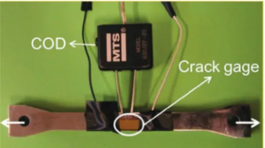
Considering the above observations, as well as safety is-sues, crack gages on SENT specimen were chosen (Fig. 5). The radius of the notch was set to 0.2 mm. It has been defined from Finite Element simulations in order to reproduce stress-strain fields similar to that found in front of an artificial notch machined in a pressure vessel to be tested under cyclic hydrogen pressure[12]. Moreover, the SENT geometry, instead of a CT geometry, was chosen to have a crack propagation in
the same direction as the expected one of a crack in the full scale gas cylinder.
Within the Mathryce project, artificial notches on the in-ternal surfaces of full scale cylinders have also been intro-duced for comparison with lab-scale further predictions. In order to have the same type of notches in both geometries (local microstructure in front of the notch), the notches were also machined by electro discharge machining (EDM) in the SENT specimen.
Strain gages used under hydrogen pressure usually present a shift of their signal that may or may not saturate in a reasonable time, due to hydrogen permeation in the glue, the substrate and/or the metallic parts. The use of crack gages avoid this problem as shown inFig. 6corresponding to a test performed at 10 MPa H2. Each time a copper wire is broken by
the crack propagation, a clear potential drop is observed. Each crack gage consists of 50 copper wires, 50 mm thick, spaced by 50 mm of electrical insulator[13]. Using this crack gage, with a special procedure to stick it on the notch tip, crack initiation corresponds to a crack length less than 100 mm.
For these tests, due to experimental constraints, only one crack gage on one side of the sample was used. The optical analysis of the specimen tested under air gives an idea of the uniformity of crack initiation. A maximum factor of 2 in the number of cycles to create a 0.1 mm surface crack could be observed between both sides of a given specimen. Interrupted tests under hydrogen pressure confirmed this ratio. This disparity can be caused by the fact that micro-cracks initiate first independently along the 10 mm large notch before forming a single crack across the whole specimen. A second cause could be the testing device misalignment. However, the alignment was considered acceptable since the crack front obtained after a few mm growth was reasonably parallel to the notch front.
Fatigue crack growth
SENT and CT specimens were used to address fatigue crack growth under hydrogen pressure in the same testing device as described above. Fatigue crack growth has been measured by two different techniques. First with the compliance method using an MTS crack opening displacement (COD) device as shown inFig. 5. Second, the crack gage can also be used to this Fig. 5 e SENT specimen with a crack gage and a clip gage.
purpose. As already discussed, the COD device presents a signal drift due to hydrogen permeation. However, this drift is low compared to the load-unload cycle duration. It has been checked that the crack growth measured by the compliance method using the COD device is consistent with the values obtained with the crack gages and also with the visually measured crack length on the specimen at the end of the test.
Results and discussion
Fatigue crack initiation
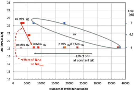
The fatigue crack initiation results obtained on the 25CrMo4 steel are presented inFig. 7. In this figure, DK is calculated from elastic theory assuming the notch is a crack. All the specimens tested have the same geometry, thus the change in DK corresponds to a change of the applied load. All the tests presented here were performed at a load ratio R equal to 0.1. The applied load frequency was 0.5 Hz.
The first main results is that hydrogen gas has a strong influence on fatigue crack initiation. As it was expected, at 10 MPa H2, a decrease of DK (or of Kmaxsince R is kept
con-stant) leads to an increase of the number of cycles to initia-tion. However, the slope of the curve (DK versus Ninit) under
hydrogen is steeper than under air. These results seem to indicate that even if the plastic zone size is decreased the hydrogen affected zone remains sufficiently large to generate a defect with a critical size in terms of crack initiation.
The effect of pressure was studied for a given DK and R ratio. Tests performed under air or under H2pressure from
0.5 MPa up to 30 MPa are also displayed inFig. 7and inFig. 8. First, the disparity in terms of number of cycle for initiation tends to be lower under hydrogen pressure than under air. Second, although these tests need to be confirmed by further
results, a continuous decrease of the number of cycles to initiation is observed as the pressure is increased. If confirmed, it would be necessary to check if this tendency continues up to 100 MPa. Indeed, such H2pressure is the working one in buffer
pressure vessels in refueling station for example.
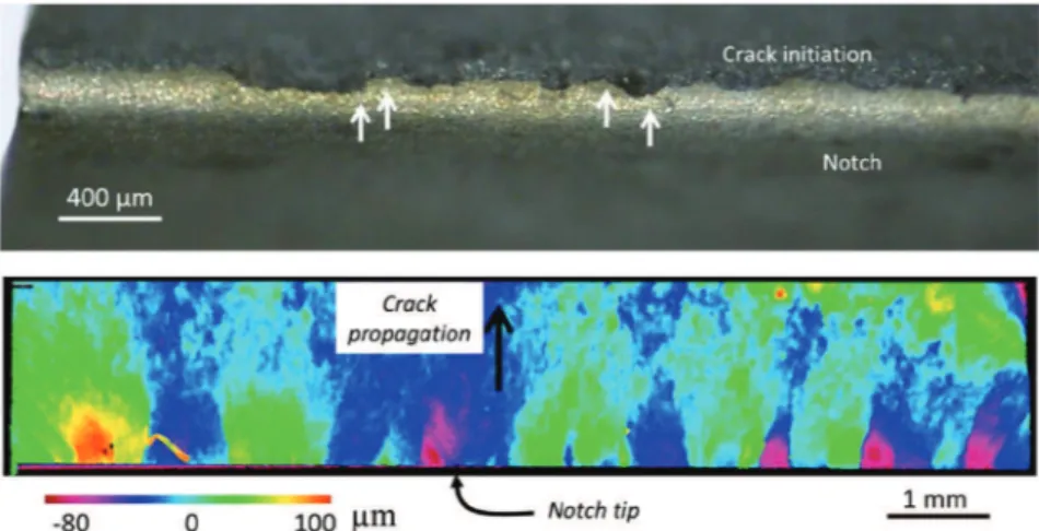
InFig. 9, the topology of the crack initiation region is pre-sented. In front of notch, up to approximately 500 mm from the notch tip, the fracture surface presents different steps with the height of ±100 mm. Such steps have also been identified under air.
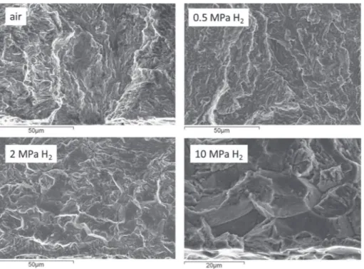
A SEM analysis of the fracture surface in the crack initia-tion area is shown inFig. 10(low magnification) and inFig. 11
(higher magnification). Under air or 0.5 MPa H2, no main
dif-ferences are observed. By contrast, the fracture surfaces ob-tained at H2pressures higher than 2 MPa reveal a clear change
of morphology. Indeed, even in the first tens of mm in front of the notch tip, an intergranular appearance is frequently Fig. 7 e Fatigue crack initiation results on SENT specimens (R ¼ 0.1, RT).
Fig. 8 e Number of cycles for initiation versus pressure at F ¼ 6 kN e R ¼ 0.1.
observed, with also the presence of secondary cracks. The size of these zones is around 20 mm, which is in line with typical prior austenite grain size on low alloy Q&T steels. In parallel, EBSD analysis of the material microstructure in this region was carried out and the data were then treated with the ARPGE software[14,15]. This software allows to reconstruct the prior austenite parent grains from the orientation of the actual grains obtained after the Q&T heat treatment opera-tion. From the first results of this running analysis, the prior austenite grains size was estimated close to 30 mm. Since no other microstructural elements have an equivalent size, one may reasonably state that the intergranular shape of H-assisted fracture is related to the prior austenite grains.
Few references deal with the influence of hydrogen on fa-tigue crack initiation. Studying 304 or 316L stainless steels, Murakami and Matsuoka[16]have shown that increasing the hydrogen concentration increased the number of cycles necessary for crack initiation to occur as compared to an un-charged specimen. By contrast, and for the same steels, other authors did not observe any influence of hydrogen on fatigue crack initiation[17]. Kesten developed a device to periodically increase the internal pressure of a tubular notched specimen on a quenched and tempered CeMn steel[18]. The tests were performed under oil and hydrogen at 20 MPa. Results showed that the number of cycles for crack initiation drops by an order of magnitude when hydrogen is present.
Fig. 9 e Steps at crack initiation in front of the notch (10 MPa H2, Fmax ¼ 6 kN). The bottom figure displays the altitude
perpendicular to the crack propagation, highlighting the presence of steps.
Fig. 10 e Fracture surface in the initiation zone. Low magnification, the notch is on the bottom of all figures. In all cases, the loading is the same with F ¼ 6 kN and R ¼ 0.1. The notch tip is apparent at the bottom of each figure.
The comparison of the present results to the literature has to be done with care, as the crack initiation definition may not be the same. The observed changes of fracture morphology right from the first micrometers in the present study are a clear microstructural proof of the effect of hydrogen in the early stage of a crack. However, the present results may be explained by hydrogen enhanced fatigue or by no effect on crack initiation and a strong effect on small crack growth. To definitely clarify this point, a higher resolution measurement of crack length should be developed under hydrogen pressure, which remains quite challenging.
Fatigue crack growth
Although the hydrogen enhanced fatigue crack growth of CrMo steels has already been addressed by several authors
[19e21], some points still remain to be clarified. In particular, it is recognized that the FCG rate under hydrogen should decrease to reach the value obtain under air when decreasing
DK, approaching the DK threshold (Fig. 12)[21,24]. However, the effect of the frequency and of the H2pressure at these low
DK values are not well known, in particular due to the increasing duration of the tests under such loading condi-tions. However, extrapolating FCG rate values under hydrogen pressure from the classical DK range to low DK values may lead to a strong underestimation of the total life of a compo-nent as shown inFig. 12.
Murakami[16]analyzed the effect of the testing frequency working on an SCM 435 CrMo steel on hydrogen precharged specimens. The authors observed that, above a given fre-quency depending on the initial hydrogen content in the specimen, the FCG rate under hydrogen tends to that obtained under air testing conditions. This change of behavior is linked to competition between the FCG rate and H diffusion rate leading to a critical FCG rate above which no effect of hydrogen can be observed. The diffusion length during one cycle is given by:
d ¼ ffiffiffiffiffiffiffiffi
D=f
q
(2) where f is the testing frequency (Hz) and D is the diffusion coefficient (m2/s). The crack increment during one cycle is
obtained experimentally by the da/dn versus DK curves. Equaling these two lengths, one obtains an estimate of the frequency associated to this change of behavior (equation(3))
[25]. f ¼ D % da dnðDKÞ &2 (3)
Dealing with CrMo steels, where the diffusion coefficient of hydrogen is still quite high, this critical FCG rate is relatively high. Although this should be experimentally proved by some Fig. 11 e Fracture surface in the initiation zone. High magnification, the figures are all less than 100 mm from the notch tip. In all cases, the loading is the same with F ¼ 6 kN and R ¼ 0.1. The notch tip is apparent at the bottom of each figure.
Fig. 12 e Extrapolation of FCG data at low DK under H2
very long tests at very low frequency, one may expect no additional hydrogen effect on the FCG behavior when decreasing the frequency from [0.1e1] Hz range to lower fre-quencies more representative to the real component loading. InFig. 13, the data obtained during the present study on CT and SENT specimens under air and under several H2pressures
are presented. First, these results confirm the statement per-formed in section2.4: the FCG rates obtained by the compli-ance method and using the crack gages are equivalent. Thus, the use of crack gages is appropriate for both crack initiation and crack growth analysis when working under H2pressure.
Second, the FCG rates obtained with both geometries are also equivalent. It has already been shown that for FCG there is no constrain effect, due to the small loading at the crack tip. This would not be the case for toughness measurements. More-over, the crack propagation direction is not the same in SENT or CT specimens. In the SENT specimens the crack propagates through the thickness of the wall as for a real crack in the cylinder, whereas in the CT specimen, it propagates in the longitudinal (L) direction of the cylinder. The present results show that, in the case of the 25CrMo4 cylinders, there is no effect of the direction of crack propagation on the fatigue crack behavior.
The results obtained also show that the effect of H2
pres-sure on the fatigue crack behavior is dependent on the loading. At low DK (14 MPa m1/2) and pressures lower than
0.5 MPa, the FCG rate are roughly equivalent to that measured under air. Increasing DK leads to a change of behavior. Even at low pressure, the FCG rate is then found equivalent to that observed at high pressure. Performing tests at high H2
pres-sure necessitates expensive dedicated devices. To identify a threshold pressure above which no additional H2 pressure
effects are observed would certainly be very convenient. The present results show that deriving such a threshold will not be straightforward. Another consequence of the coupled load-pressure dependence of the fatigue crack behavior, is that
the DK value where the behavior under hydrogen tends to reach the behavior under air is also certainly pressure dependent.
The fracture surfaces along the crack propagation path are displayed inFig. 14. At a macroscopic scale, the fracture sur-faces under hydrogen look flatter than under air. Under air, some fatigue striations perpendicular to the crack propaga-tion direcpropaga-tion are frequently observed. It is much harder to find them on the specimen tested under hydrogen at 10 MPa, their shape being however quite different. Another interesting feature is that intergranular areas are observed under hydrogen, as already observed on crack initiation zones. Here again, they have a size consistent with that of the prior austenitic grains.
At a lower magnification, some facets are observed. This has already been discussed by other authors on similar steels
[11]. We also observed on the CrMo steel, that the surface proportion of these facets is higher under H2than under air at
a given DK.
Conclusion
In this study, the fatigue cracking behavior obtained on a CrMo steel under hydrogen pressure have been presented. Both crack initiation and propagation have been addressed. In order to detect crack initiation, the use of crack gages under H2
pressure has been validated. It has also been shown that these gages can be used to measure fatigue crack rate under H2
pressure. The following main conclusions have been obtained.
First, the effect of H2 pressure on crack initiation was
analyzed. Defining crack initiation as a crack 0.1 mm long from the notch tip, the number of cycles to initiation was found to decrease with an increasing H2pressure from 0.5 MPa
to 30 MPa. At this pressure, a reducing factor of 10 was observed.
Second, a coupled effect of DK and H2pressure has been
evidenced on fatigue crack growth. Indeed, at low DK and low pressure (below 0.5 MPa H2), no increase of the crack growth
rate is observed whereas it is observed at 10 MPa H2. By
contrast, at higher DK, the effect of H2at these low pressures is
similar to that obtained at 10 MPa.
The analysis of the fracture surfaces shows that the crack paths in the initiation as well as in the propagation steps are affected by the prior austenitic grains.
However, the testing methodologies developed in the pre-sent paper are not able to quantitatively discriminate to discriminate between a real effect of hydrogen on fatigue crack initiation and an effect of hydrogen on the fast growth of small cracks.
Additional tests, including tests at higher pressures are foreseen within the MATHRYCE project to confirm these re-sults. Moreover, numerical simulations are currently per-formed to analyze the results in terms of the local stress and strain fields including the plastic zone size and the level of hydrostatic stress.
Acknowledgements
The research leading to these results has received funding from the European Union's Seventh Framework Program (FP7/ 2007e2013) for the Fuel Cells and hydrogen Joint Technology Initiative under grand agreement n![303422]. The authors are also thankful to the other partners of the MATHRYCE project
[22](CCS Global Group, JRC) for useful discussions.
r e f e r e n c e s
[1] Briottet L, Moro I, Escot M, Furtado J, Sallais D, Dey R, et al. Material testing and design recommendations for
components exposed to hydrogen enhanced fatigue e the Mathryce project. Brussels: ICHS; 2013.
[2] Sims JR. Standards and codes to control hydrogen e induced cracking in pressure vessels and pipes for hydrogen gas storage and transport. In: Gangloff P, Somerday B, editors. Gaseous hydrogen embrittlement of materials in energy technologies1. Woodhead Publishing Limited; 2012. [3] San Marchi C, Somerday B, Nibur K. Development of
methods for evaluating hydrogen compatibility and suitability. Int. J. Hydrog Energy 2014;39:20434e9. [4] Nanninga NE. Fatigue crack initiation and fatigue life of
metals exposed to hydrogen. In: Gangloff P, Somerday B, editors. Gaseous hydrogen embrittlement of materials in energy technologies1. Woodhead Publishing Limited; 2012. [5] ESIS P11-02. Technical recommendations for the extreme
value analysis of data on large non-metallic inclusions in steels. Eur Struct Integr Soc 2002:29. ISSN 1616-2129. [6] ASTM E2283-08. Standard practice for extreme value analysis
of nonmetallic inclusions in steel and other microstructural features. 2008.
[7] ISO 11120-1999, Gas cylinders - Refillable seamless steel tubes for compressed gas transport, of water capacity between 150 l and 3000 l - Design construction and testing. [8] Murakami Y. Metal fatigue: effects of small defects and
nonmetallic inclusions. Elsevier; 2002.
[9] Trasatti S, Sivieri E, Mazza F. Susceptibility of a X80 to Hydrogen Embrittlement. Mater Corros 2005;56.
[10] Moro I, Briottet L, Lemoine P, Andrieu E, Blanc C, Odemer G. Hydrogen embrittlement susceptibility of a high strength steel X80. Mater Sci Engineering:A 2010;527(27e28):7252e60. [11] Macadre A, Yano H, Matsuoka S, Furtado J. The effect of
hydrogen on the fatigue life of NieCreMo steel Envisaged for
Use as a storage Cylinder for a 70MPa hydrogen station. Int J Fatigue 2011;33(12):1608e19.
[12] Briottet L, Escot M, Moro I, Tamponi GM, Furtado J, Solin J, et al. Crack initiation and propagation under hydrogen-enhanced fatigue of a Cr-Mo steel for gaseous hydrogen storage. materials for hydrogen service. Anaheim, USA: ASME 2014 Pressure Vessels & Piping Conference; July 20-24 2014. [13] Escot M, Briottet L, Moro I, Andrieu E, Blanc C, Odemer G,
et al. Hydrogen-enhanced fatigue of a Cr-Mo steel for gaseous hydrogen storage. Gent, Belgium: Steel&Hydrogen 2nd Int. Conf. on Metals and Hydrogen; May 5-7 2014. [14] Cayron C, Artaud B, Briottet L. Reconstruction of parent
grains from EBSD data. Mater Charact 2006;57:386e401. [15] Cayron C. ARPGE: a computer program to automatically
reconstruct the parent grains from electron backscatter diffraction data. J Appl Cryst 2007;40:1183e8.
[16] Murakami Y, Matsuoka S. Effect of hydrogen on fatigue crack growth of metals. Eng Fract Mech 2010;77:1926e40. [17] Gangloff R, Somerday B. Gaseous hydrogen embrittlement of
materials in energy Technologies. Woodhead Publishing in Materials; 2012.
[18] Kesten M, Windgassen KF. Design of equipment to hydrogen fatigue service. Am Soc Metals, Metals Park OH
1982;44073:389e93.
[19] Macadre A, Artamonov M, Matsuoka S, Furtado J. Effects of hydrogen pressure and test frequency on fatigue crack growth properties of NieCreMo steel candidate for a storage cylinder of a 70MPa hydrogen filling station. Eng Fract Mech 2011;78(18):3196e211.
[20] Matsuoka S, Tanaka H, Homma N, Murakami Y. Influence of hydrogen and frequency on fatigue crack growth behavior of Cr-Mo steel. Int J Fract 2010;168(1):101e12.
[21] Suresh. Fatigue of materials. Cambridge: Cambridge University Press; 1991.
[22] www.mathryce.eu.
[23] Somerday P, Sofronis P, Nibur KA, San Marchi C,
Kirchheim R. Elucidating the variables affecting accelerated fatigue crack growth of steels in hydrogen gas with low oxygen concentrations. Acta Mater 2013;61:6153e70. [24] Suresh S, Ritchie R. On the influence of environment on the
load ratio dependence of fatigue thresholds in pressure vessel steels. Eng Fract Mech 1983;18:785e800.
[25] Moro I, Briottet L, Lemoine P, Doyen O, De Dinechin G. Fatigue crack growth of a C-Mn steel and associated weld under hydrogen pressure, 2012 International hydrogen conference. In: Hydrogen-materials interactions. Wyoming, USA: Jackson Lake Lodge; September 9-12, 2012.
![Fig. 2 e Example of reconstruction of austenitic parent grains with the ARPGE software (using the Greninger-Troiano orientation relationship) [15].](https://thumb-eu.123doks.com/thumbv2/123doknet/3203542.91556/4.892.130.389.430.633/example-reconstruction-austenitic-software-greninger-troiano-orientation-relationship.webp)