UNIVERSITY OF LIEGE
Contribution to the Characterization
of Piston Expanders for their Use
in Small-Scale Power Production Systems
A Thesis
Submitted to the Faculty of Applied Sciences
of the
University of Liège (Belgium)
by
Jean-François Oudkerk
In partial fulfillment of the requirements for the degree
of
Doctor of Applied Sciences
Acknowledgements
I would like to thank Prof. Vincent Lemort who gave me the opportunity to work in his team and to do this thesis. I’m grateful for his encouragement, his trust and all what I learned from him.
I would also like to thank all the people I had the chance to work with during these years. A large part of this work would not have been possible without the help, trust and involvement of Thierry Carrette, Pierre Detré and Thomas Briamont from Coretec and Remi Daccord, Julien Melis and Antoine Darmedru.
Thank you to all my colleagues from the Thermodynamics Laboratory for their help, their support, the team spirit and all the enjoyment we had together. Special thanks to Richard Labenda, Bernard Loly and José Concha for their work on test benches and their numerous sound advices.
I also want to thank all my friends to be there in good and hard times, special thanks go to “La Chaîne” for their presence during this thesis. I thank my mother and Jean for their sacrifices, unwavering support and love. Finally, a very special word of thanks to Marie for her encouragement and help.
Abstract
Piston expanders are well suited for small scale power generation (<50kW) using heat engines such as Ericsson engine or Organic Rankine Cycle (ORC) system. Both systems offer the possibility to use renewable energy sources and are increasingly considered in light of the economic and environmental context. This thesis aims at contributing to the knowledge and the development of piston expanders by presenting modeling, simulation and experimental investigations.
Two types of piston engine models are proposed. The first type (denoted as “detailed”) describes the shaft angle (or time) evolution of the state of the fluid in the control volume limited by the cylinder wall and the piston. The second type of model (denoted as “semi-empirical”) is based on theoretical indicator diagram. A calibration process is proposed and applied with the measurement collected on two different expanders.
The detailed model is first used to simulate an Ericsson engine. The simulations allow for the optimization of the pressure ratio, the determination of the ratio between the swept volumes of the expander and the compressor, the computation of the valve timing and the evaluation of the potential performances.
The main modifications made to turn an available Internal Combustion Engine (ICE) into an Ericsson engine are described. This prototype is then tested but did not run as expected. The identified reasons are a too high leakage rate, a too large cut-off ratio and a too low expander supply temperature. These three features led to insufficient pressure. Nevertheless, a compressor is used to rise the pressure up to 7 bar in order to test the expander part. This expander shows a maximal isentropic efficiency of 59% at 600 RPM with a pressure ratio of 5.
A swash-plate expander integrated into an ORC using R245fa is also investigated in a wide range of operating conditions. Performance maps in terms of pressure ratio and rotational speed are given. Maximal reached isentropic efficiency is 54% at 2500 RPM for a pressure ratio of 10.5.
Experimental results obtained on both expanders are analyzed with the same methodology to assess the importance of each source of losses. This methodology is based on the disaggregation of the isentropic efficiency into different factors. Each of these factors represents one source of losses. In-cylinder pressure measurements are performed in order to measure mechanical losses. Leakage effects are simulated with the detailed model.
Finally, an Ericsson engine-based m-CHP unit and an ORC-based m-CHP unit using the swash-plate expander are simulated with the validated semi-empirical model. Ericsson engine system shows a 6.5% electrical efficiency while the ORC system shows en efficiency of 8.2%. For both systems, possible improvements are simulated. It is shown, among other things, that the benefit of an increase of the built-in volume is limited by the decrease of the mechanical efficiency.
Chapter 1: Introduction………9
1. Context………..10
2. Motivation of the work………..11
3. Overview………13
4. References………14
Chapter 2: Piston expanders and their use in Rankine cycle and Ericsson heat
engines………..15
1. Introduction………17
2. Piston expander description……..……….17
3. Ericsson engine……….28
4. Rankine cycle……….36
5. Conclusions. ………..42
6. References………..43
Chapter 3: Modeling piston expanders………...47
1. Introduction………48
2. Detailed model……….49
3. Semi empirical model………..59
4. Friction model………62
5. Conclusions……….65
6. References………66
Chapter 4: Development of an Ericsson engine………69
1. Introduction………71
2. Preliminary design of an Ericsson engine………..………71
3. Prototype development and test bench ………79
4. First experimental results………..…..86
5. Second set of experimental results………..…….88
6. Detailed model validation and analysis………..….101
7. Comparison between design and post-validation simulations………..……….107
9. Conclusions……….……….112
10. References………114
11. Annexes………..115
Chapter 5: Experimental investigation of a piston expander integrated into an
ORC cycle………..124
1. Introduction………..126
2. Description of the test bench ………..126
3. Experimental results………129
4. Detailed model validation and analysis……….………141
5. Semi-empirical model validation………147
6. Conclusions………149
7. References……….151
8. Annexes………152
Chapter 6: Performance evaluation of ORC-based and Ericsson engine-based
combined heat and power systems………...………156
1. Introduction……….…157
2. Interest of cogeneration and performance indicators………..158
3. Ericsson engine based CHP unit……….160
4. ORC-based CHP unit………..164
5. Potentials improvements………..172
6. Conclusions……….179
7. References………181
𝐴𝑈 Overall heat transfer coefficient
[W/K] 𝑡 Time [s]
𝐴𝑣 Valve flow cross section area [m] 𝑢 Specific internal energy [J/kg] 𝐵 Connecting rod length [mm] 𝑉 Inlet closing or cut-off volume [m³]
𝐶̇ Heat capacity flow [W/K] 𝑣 Specific volume [m³/kg]
𝐶𝑑 Flow coefficient [-] 𝑉0 Clearance volume [m³]
𝐶𝐹 Clearance factor [-] 𝑉𝑡𝑜𝑡 Volume total [m³]
𝐶𝑂 Cut-off ratio [-] 𝑊̇ Mechanical or electrical power
[W]
𝐶𝑝 Mean piston speed [m/s] 𝑊 Work [J]
𝑐𝑝 Constant pressure specific heat
capacity [J/(K.kg)] Greek symbols
𝑐𝑣 Constant volume specific heat capacity [J/(K.kg)] 𝜖𝑖𝑛 Diagram factor [-]
𝐷 Bore diameter [m] 𝜖𝑠 Isentropic efficiency [-]
𝐷𝑠 Valve stem diameter [m] 𝜖𝑠𝑝,𝑖𝑛 Specific diagram factor
𝐷𝑣 Valve head diameter [m] 𝜂 Efficiency [-]
𝐷𝑣𝑖 Valve inner seat diameter diameter [m] 𝛾 Isentropic ratio [-] 𝑒 Fuel CO2 specific emission
[kgCO2/MWh] 𝜔 Rotational speed [°/s]
𝐸̇𝑜𝑢𝑡 Net outlet energy flow [W] 𝜙 Filling factor [-] or Volume ratio [-] 𝑓𝑚𝑒𝑝 Friction mean effective pressure [bar] 𝜙𝑖𝑛 Internal filling factor [-]
ℎ Specific enthalpy [J/kg] 𝜙𝑙 Leakages filling factor [-] ℎ𝑐 Convective heat transfer coefficient
[W/(K.m²)] 𝜌 Density [kg/m³]
𝐻̇𝑖𝑛 Net inlet enthalpy flow [W] 𝜎 Standard deviation 𝑖𝑚𝑒𝑝 Indicated mean effective pressure [bar] 𝜃 Shaft angle [°] 𝐿 Piston stroke [m]
𝐿𝐻𝑉 Lower heating value [W/kg] Subscripts
𝐿𝑣 Valve lift [m] 𝑎 Air
𝑀̇ Mass flow rate [kg/s] 𝑎𝑚𝑏 Ambient
𝑚 Mass [kg] 𝐶𝐶𝐺𝑇 Combined Cycle Gas Turbine
𝑀𝐴𝑅𝐸 Mean Relative Error [%] 𝑐𝑑 Condensing or Condenser
𝑁 Rotational speed [Hz] 𝐶𝐻𝑃 Combined heat and power
𝑛𝑐𝑦𝑙 Number of cylinders [-] 𝑐𝑜𝑟 Corrected
𝑁𝑢 Nusselt number [-] 𝑐𝑝 Compressor
𝑃 Pressure [Pa] 𝑐𝑟𝑖𝑡 Critic
𝑃𝐸𝑆 Primary Energy Saving [%] 𝑑𝑜𝑤𝑛 Downstream
𝑃𝑟 Prandtl number [-] 𝐸𝐶 Exhaust closing
𝑄̇ Heat power [W] 𝑒𝑙 Electric
𝑅𝑎 Rayleight number [-]] 𝐸𝑂 Exhaust opening
𝑅𝑒 Reynolds number [-] 𝑒𝑣 Evaporating or Evaporator
𝑅𝑝 Pressure ratio [-] 𝑒𝑥 Exhaust
𝑟𝑇 Temperature ratio [-] 𝑒𝑥𝑝 Expander
𝑟𝑣,𝑖𝑛,𝑐𝑝 Compression built-in volume ratio [-] 𝑔 Saturated gases 𝑟𝑣,𝑖𝑛,𝑒𝑥𝑝 Expansion built-in volume ratio [-] ℎ𝑥 Heat exchanger
𝐼𝐶 Inlet closing 𝐼𝐶 Inter cooler
𝑖𝑛 Indicated or Internal 𝑠 Entropy [J/(kg.K)]
𝑆𝑐𝑜2 CO2 Saving [kgCO2/MWhe] 𝑇 Temperature [°C] or torque [N.m] 𝐼𝑂 Inlet opening 𝑙 Saturated liquid 𝑙𝑒𝑎𝑘 Leakage 𝑙𝑜𝑠𝑠 Losses 𝑚 Mechanical 𝑚𝑓 Mechanical friction 𝑚𝑖𝑛 Minimum 𝑛 Net 𝑜𝑝𝑡 Optimal 𝑜𝑢𝑡 Out or Outdoor 𝑝𝑝 Pump or Pinch-Point 𝑟𝑒𝑓 Reference 𝑟𝑒𝑔 Regenerator 𝑠 Isentropic 𝑠𝑐 Sub cooling 𝑠ℎ Shaft 𝑠ℎ Super heating 𝑠𝑢 Supply 𝑡ℎ Theoretical or Thermic 𝑡ℎ𝑟 Nozzle throat 𝑢𝑝 Upstream 𝑤 Wall or Water 𝑤𝑓 Working fluid Acronyms
BTC Bottom Dead Center
CCGT Combined Cycle Gas Turbine CHP Combined Heat and Power HTF Heat Transfer Fluid
IC Inter Cooler
ICE Internal Combstion Engine
IPCC Intergovernmental Panel on Climate Change
ORC Organic Rankine Cycle
PV Pressure Volume
RC Rankine Cycle
TDC Top Dead Center WHR Waste Heat Recovery
9
1.
Chapter 1: Introduction
Contents
1. Context ... 10
2. Motivation of the work ... 11
3. Overview ... 13
Chapter 1: Introduction
10
1. Context
From an economic point of view, the rise of energy price over the last 20 years has pushed our society to consume energy more and more rationally. For this purpose, new and more efficient systems are in development such as waste heat recovery, cogeneration or use of solar energy. Moreover, before 2003, the European electricity market was subject to a regulated natural monopoly. Since 2004 for the professional sector and 2007 for private individuals, the electricity and gas markets have been liberalized (SPF Economie 2008). This liberalization has given the opportunity to everyone connected to the electricity grid to produce and sell electricity. Consequently, today, everyone can make profitable a distributed electricity production such as photovoltaic panels or CHP unit.
Another important purpose is the energetic dependence. Indeed, the European Union meets 50 % of its energy needs with importation and this ratio will reach 70 % in 2030 if the trend is maintained (Comission Européenne 2006). This strong dependency on exporting countries could lead to a lack of supply and a more accentuated price rise.
Another observation is that, in this beginning of 21st century, environmental and energetic concerns
have never been so strong. Indeed, the fossil energy resources are in depletions and their use leads to a pollution of the environment. Table 1-1 summarizes the situation of the world fossil fuels reserves (these numbers have to be considered as orders of magnitude given the incertitude linked to this matter).
Table 1-1: World fossil fuels reserves (AFH2 2007)
Proven world reserve [Gtep]
Annual consumption [Gtep]
Duration (at current consumption rate) [year]
Oil ~140 3.9 ~40
Natural gas ~160 2.4 ~60
Coal ~600 2.8 ~200
Concerning the pollution associated to the use of fossil fuels, CO2 emissions are generally the first concern. Indeed, according to the IPCC, greenhouse gas emissions are leading to climate change, which will cause dramatic consequences for the planet such as melt of ice sheet, rise of sea level, increase of natural disasters frequency and negative impacts on biodiversity. Among greenhouse gases, CO2 is the principal one and 84% of its emissions are attributed to the energy sector (Quadrelli and Peterson 2007).
Hence, the necessity to reduce fossil fuels consumption and emissions of greenhouse gases has been pointed out for several years. This necessity led to international treaties such as the Kyoto protocol in 1997 (AFH2 2007). This one aims for the stabilization of the greenhouse gases to the 1990 level. More recently, in 2015, the COP21 took place in Paris where 195 states agreed to limit the increase in global average temperature below 2°C compared to pre-industrial level by reducing greenhouse gas emission. Each country has to publish its contribution depending on their specificities and constraints.
11 In order to improve the situation in Europe, several regulations and directives concerning the rational use of energy and pollutant emissions give some guidelines and constraints to the Member States. For example, directive 2010/31/UE concern the buildings energetic performance and constrains Member States to ensure a feasibility study on high efficiency system (such as CHP) to be performed for each new building. The directive 2004/8/CE gives a common framework for high efficiency cogeneration and constrains States to publish reports on the state of this sector and to encourage it. The regulation (EC) No 715/2007 fixes the rules to measure pollutant emissions and maximal values of these emissions. In a more general way, the decision No 406/2009/EC gives the contribution of each Member State in order to respect commitments in terms of reduction of greenhouse gases. Through this context analysis, it can be concluded that alternatives to the current energy sources and conversion systems are needed in terms of economic and environmental purposes. To push forward this energetic transition, authorities have started to put in place incentives, regulations and frameworks. Moreover, profitable opportunities can be found in this energetic challenge.
2. Motivation of the work
The analyses of economic, environmental and political contexts show the need to develop more efficient use of energy as well as to shift from fossil fuels to renewable energy sources. In this scope, small-scale Ericsson engine and Rankine Cycle (RC) or Organic Rankine Cycle (ORC) are interesting and gain more and more interest. Indeed, both systems are external combustion engines and then show the advantage to allow the small scale (<50 kW) production of electricity by using renewable heat sources such as biomass, solar and geothermal especially for CHP application. Another main application is the recovery of heat loss from industrial processes and from automotive and truck Internal Combustion Engines (ICE).
While large-scale ORC plants use turbomachines as expansion machines, volumetric expanders such as scroll, screw or piston machines are often preferred for small-scale applications. In the same way, the Ericsson engine operates with the same thermodynamic cycle as the gas turbine (the Brayton cycle) but uses piston machines instead of turbomachinery. Indeed, according to several studies, volumetric expanders are more suited for small-scale application because of their lower rotational speed. In a general way, the similarity concept using specifics speed (Ns) and diameter (Ds) gives boundaries between technologies of expansion machine (Baljé 1962). This concept is illustrated by the Ds-Ns diagram shown in Figure 1-1 where efficiency maps are plotted for turbo machinery and volumetric machines. This diagram shows that volumetric machines such as pistons expanders are suited for low specific rotational speeds, while turbines have good efficiency at high specific speed. As specific speed is proportional to the square root of the volume flow rate, low specific speed means low volume flow capacity and small-scale power.
Chapter 1: Introduction
12
Figure 1-1: Specific speed and diameter diagram (Baljé 1962)
In addition to the low rotational speed, volumetric expanders have the advantages to handle high pressure ratio and the ability to ingest liquid droplets. On the other hand, they are generally bulkier than turbines. Recently, a lot of researches and developments have been carried out on positive displacement machines for small-scale applications. Most of these works deal with scroll, screw, piston and vane types. Among these different expander types, piston type shows some advantages such as larger built-in volume ratio, high robustness and high achievable supply pressure and temperature. For these different reasons, piston expanders are more and more considered for ORC and , especially for micro-CHP applications and for waste heat recovery in mobile applications. However, there is a lack of modern scientific literature with experimental work focusing on piston expander used in ORC . Indeed, most of the experimental publications focus on the system level and did not enter in detail concerning the losses affecting the expander. Moreover, less publications can be found on piston expanders compared to other type of volumetric engines. For example, in (Quoilin 2015), a database of 954 publications from 1972 to 2015 on ORC from Elsevier, Sage, ASME and MDPI relates 51 publications specifically on volumetric expanders. From these 51 publications, only 4 are related to piston expanders while 23 deal with scroll expanders and 11 with screw expanders. Regarding Ericsson engines, only 3 modern experimental campaigns have been found in the literature by the author (an exhaustive literature review will be presented in Chapter 2).
Consequently, the main objective of this thesis is to characterize operation of modern piston expanders used in ORC and Ericsson engines through the identification and quantification of losses and potential improvements. Other objectives are to propose efficient ways to model piston expanders for simulation in thermal systems and to evaluate performance of CHP-applications using such technologies.
13
3. Overview
The present thesis is organized as follows:
Chapter 2 summarizes the state-of-the-art of piston expanders and their use in Ericsson engines and
Rankine cycle systems. The piston expander is described in terms of working principle, mechanical design, thermodynamic aspects and performance indicators. Then Ericsson engine and Rankine cycle system basic principles are recalled and a review of the use of piston expanders for these applications is presented.
Chapter 3 presents two simulation models. The first model, more detailed, is based on the evolution
over one revolution of the state of the working fluid in the control volume defined by the cylinder. The second model, denoted as a “semi-empirical” model, is based on the theoretical indicator diagram. Both are 0D model but the first one is time dependent and uses a detailed geometrical description while the second uses lumped parameters.
Chapter 4 describes the experimental work done by the author in the context of a project aiming at
developing an Ericsson engine by modifying an existing ICE. First, the detailed simulation model is used to design main geometrical parameters. Then, the modifications made on the ICE to build the prototype are presented. Finally, experimental results are exploited to analyse the performance and the losses of the expander part of the engine and to validate the models presented in Chapter 3.
Chapter 5 presents the experimental investigation performed on a swash plate piston expander
integrated into an ORC system. Isentropic efficiency and shaft power maps are established with the measurements. Then, as in Chapter 4, analyses of the different sources of losses are presented and models are validated.
Chapter 6 aims at evaluating performance of cogeneration systems. The first system is based on an
Ericsson engine with the piston machine tested in Chapter 4 while the second system uses an ORC system with the piston expander tested in Chapter 5. Evaluation of CHP efficiencies is obtained by simulation with the help of the semi-empirical models validated with the experimental results.
Chapter 1: Introduction
14
4. References
AFH2. 2007. “Situation Mondiale de l’Energie.” Mémento de l’Hydrogène Fiche 2.1. Association Française de l’Hydrogène.
Baljé, O. E. 1962. “A Study on Design Criteria and Matching of Turbomachines: Part A—Similarity Relations and Design Criteria of Turbines.” Journal of Engineering for Power 84 (1): 83. doi:10.1115/1.3673386.
Comissoin Européenne. 2006. “Attitudes Au Sujet de L’énergie.” Eurobaromètre Spécial.
Quadrelli, R., and S. Peterson. 2007. “The Energy–climate Challenge: Recent Trends in CO2 Emissions from Fuel Combustion.” Energy Policy 35 (11): 5938–52. doi:10.1016/j.enpol.2007.07.001. Quoilin, S. 2015. “Keynote Lecture: Past and Current Research Trends in ORC Power Systems.” In 3rd
International Conference on ORC Power Systems. Brussels, Belgium. http://orbi.ulg.ac.be/handle/2268/186850.
SPF Economie. 2008. “Projet d’Etude Sur Les Perspectives d’Approvisionement En Electricité.” Belgique: Bureau Fédéral du Plan.
15
2.
Chapter 2: Piston expanders and their use in
Rankine cycle and Ericsson heat engines
Contents
1. Introduction ... 17
2. Piston expander description... 17
2.1. Working principle ... 17
2.2. Mechanical design ... 19
2.2.1. Reciprocating motion conversion system ... 19
2.2.2. Types of valves ... 20
2.2.3. Double acting piston expander ... 21
2.3. Thermodynamic aspect and losses ... 21
2.3.1. Losses... 21
2.3.2. Mass flow rate ... 25
2.3.3. Indicated and mechanical power ... 25
2.4. Performances indicators... 26
2.4.1. Volumetric performance ... 26
2.4.2. Energy conversion efficiency ... 26
2.4.3. Compactness ... 27
3. Ericsson engine ... 28
3.1. Working principle ... 28
3.2. Previous work on Ericsson engine ... 32
4. Rankine cycle ... 36
4.1. Working principle ... 36
4.2. Previous work on the use of piston expander in (Organic) Rankine cycle ... 37
4.2.1. Steam cars ... 37
4.2.2. Expansion valve in CO2 cycle ... 37
4.2.3. WHR in vehicles ... 38
Chapter 2: Piston expander and their use in Rankine cycle and Ericsson heat engines
16
4.2.5. ORC in general and flash cycle... 40
4.2.6. Others applications... 40
4.2.7. Conclusion ... 41
5. Conclusions ... 42
17
1. Introduction
The piston expander, or reciprocating expander, is one of the major types of positive displacement expander. This type of machine converts the energy contained in a pressurized fluid into mechanical energy by increasing the volume of a working chamber and then, decreasing the pressure of the fluid. The piston expander is among the oldest displacement machines. It has been largely used during the Industrial Revolution and up to the beginning of the 20thcentury. There is currently a large regain of
interest for piston expanders in small-scale application such as Ericsson engine and Rankine cycle systems used for micro-CHP, solar application and waste heat recovery on internal combustion engines (see literature review in section 3.2 and 4.2). Piston expanders actually show some advantages over other expansion machines, such as larger built-in volume ratio, high achievable operating pressures and temperatures, their ability to ingest liquid and low rotational speeds.
2. Piston expander description
2.1. Working principle
Reciprocating expanders use one or several pistons moving inside cylinders from the top dead center (TDC) to the bottom dead center (BTC) with a reciprocating motion. The cylinder has some openings by which the working fluid can enter and leave the cylinder. In order to explain the working principle of such expander, a theoretical pressure-volume diagram, called “indicator diagram”, is shown in Figure 2-1. This diagram shows the six steps of the expansion process.
At initial position 1, the piston is at the TDC and the volume is clearance volume 𝑉0. At this point, the inlet ports opens and the piston starts its down-stroke. The pressurized fluid enters into the cylinder until the inlet port closes. The volume at this moment is the off volume and is generally described by the cut-off ratio defined as the ratio between the inlet closing volume (𝑉𝐼𝐶) and the total volume (𝑉𝑡𝑜𝑡).
𝐶𝑂 = 𝑉𝐼𝐶
𝑉𝑡𝑜𝑡 ( 2-1 )
Then, at position 2, inlet and exhaust ports are both closed and the expansion of the fluid begins. Indeed, the volume in the cylinder increases while the piston continues his down-stroke, leading to a decrease of the pressure. This process takes part until the piston reaches the BTC at which the volume is maximal (𝑉𝑡𝑜𝑡). The built-in volume ratio is defined as the ratio between the volumes at the end and at the beginning of the expansion. Depending on pressure ratio applied to the expander and on the built-in expansion volume ratio, the pressure at the end of expansion process is either higher (under expansion), equal, or lower (over expansion) than the exhaust pressure.
𝑟𝑣,𝑖𝑛,𝑒𝑥𝑝 =𝑉𝑉𝑡𝑜𝑡 𝐼𝐶 =
1
𝐶𝑂 ( 2-2 )
When the piston reached the BDC (point 3), the exhaust port opens and some fluid leaves or enters the cylinder (depending whether the pressure is respectively higher or lower than the exhaust pressure) until
Chapter 2: Piston expander and their use in Rankine cycle and Ericsson heat engines
18 pressure inside the cylinder reaches the exhaust pressure. At this position, the piston starts its up-stroke and pushes out the remaining fluid. This exhaust process occurs until the exhaust ports are closed. At position 5, the exhaust ports closes and the inlet port remains closed. From this position, the piston continues is up-stroke towards the TDC and the fluid is compressed. This compression phase lasts until the piston reaches the TDC. The built-in compression ratio is defined as the ratio between the volumes at the beginning and at the end of the compression. These two volumes are respectively the exhaust closing volume (𝑉𝐸𝐶) and the clearance volume (𝑉0).
𝑟𝑣,𝑖𝑛,𝑐𝑝 =𝑉𝑉𝐸𝐶
0 ( 2-3 )
Similarly to the expansion process, three different situations may occur at the end of compression process: pressure is higher (over compression), equal or lower (under compression) than the supply pressure. When the piston is back to the TDC, inlet port opens and some fluid enters or leaves the cylinder, respectively in the case of under or over compression, until the pressure in the cylinders is equal to the supply pressure.
Figure 2-1: Theoretical indicator diagram of a piston expander
This description of the working principle of piston expander shows that four main geometrical parameters allow describing the theoretical indicator diagram: the total displacement 𝑉𝑡𝑜𝑡; the clearance volume 𝑉0; the inlet closing volume 𝑉𝐼𝐶 and the exhaust closing volume 𝑉𝐸𝐶. As it will be shown latter, these parameters determine the power and mass flow rate of the expander.
It should be noted that in practice, the inlet valve can open before the piston reaches the TDC and the inlet opening volume 𝑉𝐼𝑂 can be different than the clearance volume. In the same way, the exhaust valve can open before the piston reaches the BDC and the exhaust opening volume 𝑉𝐸𝑂 can be different of the total displacement. This anticipation of the opening of the ports can be done in order to reduce the pressure
19 drop or can be a consequence of the type of valves used, as with piston-controlled exhaust port where 𝑉𝐸𝑂= 𝑉𝐸𝐶.
2.2. Mechanical design
Different types of piston expander exist and are characterized by their mechanical design. Reciprocating expanders differ by:
- The mechanism used to convert the reciprocating motion into a rotating motion - The type of valves and their location
- The action of the fluid upon the piston, simple or double acting
2.2.1. Reciprocating motion conversion system
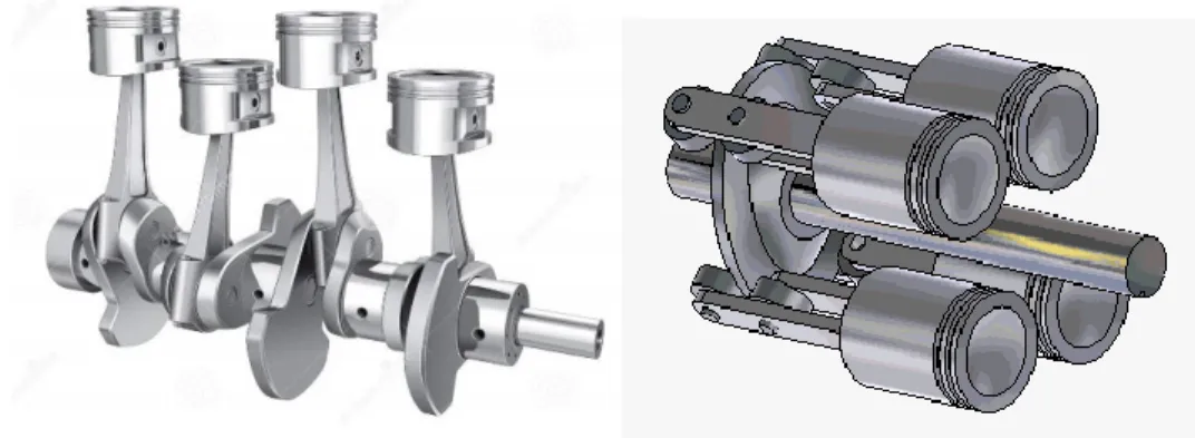
The reciprocating motion of the piston is not easy to use directly and is more often converted into a rotational motion. In order to do this, two main mechanisms are used: crank train or swash/wobble plate. The crank train mechanism is composed of a camshaft and connecting rods connected to the piston pins and the crank pins. This system is the one used in internal combustion engines (ICE). In axial piston machine, the pistons are disposed in parallel and around the shaft. The rotational motion of the shaft is converted into a reciprocating motion with the help of tilted plate connected to the pistons rods. The rods are either fixed to this plate with ball joints or are sliding on the plate and linked to it with cams. In the former system, the plate has an oscillating movement and is called “wobble plate”. In the second system, the plate rotates and is called “swash plate”. For the wobble plate, the oscillation movement induced by a Z-shaft or by a second tilted plate (see Figure 2-3). Axial piston machines are often used as compressors in mobile air conditioning applications and are more compact than crank train piston machines.
Figure 2-2: Reciprocating to rotational motion system conversion. Crankshaft on the left and swash-plate on the right.
Chapter 2: Piston expander and their use in Rankine cycle and Ericsson heat engines
20
Figure 2-3: Axial piston mechanism: a) swash plate, b) wobble plate with sliding plate, c) wobble plate with Z-shaft (Grip 2009)
Some piston expanders are classified as “free-piston” engines. In this configuration, the reciprocating motion of the pistons is directly used to activate a piston compressor (e.g. in Ericsson engine (Mikalsen and Roskilly 2012) or in CO2 compression cycle (Heyl and Quack 1999)) or to produce electricity with a linear generator. This configuration has less moving parts in contact and hence less friction losses.
2.2.2. Types of valves
Unlike in piston compressors, the pressure gradient across the expander is in the opposite direction to the fluid flow. Consequently, check valves cannot be used and the opening and closing of the ports have to be actuated. This actuation system makes the expander more complex and then less robust and leads to additional losses.
As explained above, the inlet and exhaust closing and opening volumes define the operating cycle of the piston expander. So it is the timing of the valves, i.e. the moments at which the vales open and close, that determines important geometrical parameters such as the cut-off ratio and the built-in compression ratio. Different types of valves and actuation systems can be used. The main types are poppet valves (as in fours stroke ICE), piston-controlled ports (as in small two stroke ICE), rotary valves and sliding valves (Figure 2-4). The valves are usually mechanically actuated but sometimes electrical actuation is used, for example with solenoid valves, to easily control and modify the timing of the valves. Poppet valves are generally actuated with a camshaft and the profile and the position of the cams defined the timing. Since piston-controlled ports are closed and opened by the piston covering and uncovering the ports, they do not need an actuation system and are then simpler and avoid valve train mechanical losses. The timing is fixed by the position of the port along the cylinder and the opening and closing is always symmetrical with respect to top dead center. With rotary valves, the timing can be modified by modifying the rotational speed of the valve. An effective way to control the opening duration of a port is to use two valves in series and to adjust the opening overlap.
21
Figure 2-4: Types of valve: a) poppet valve, b) supply sliding valve and piston-controlled exhaust port, c) rotary valve (Wronski 2015)
The location of supply and exhaust valves can differ, determining the flow configuration. In crossflow engine, both supply and exhaust valves are located close or on the cylinder head. In uniflow expander, the supply port is close to the cylinder head while the exhaust port is close to the bottom of the cylinder and is in general a piston-controlled exhaust port (see Figure 2-4). Some engines, denoted as multiflow, combined the two systems with an exhaust port close to the cylinder head and another close to the cylinder bottom. The advantage of the uniflow configuration is that the cylinder head is not cooled down during the exhaust process, leading to a higher wall temperature and less risk of condensation (if vapor is used as working fluid) during supply process.
2.2.3. Double acting piston expander
In some expanders, the fluid acts alternatively on the two faces of the piston in the same cylinder. This configuration is denoted as double acting and leads to a more compact engine as two expansion processes occur in one cylinder.
2.3. Thermodynamic aspect and losses
2.3.1. Losses
Several sources of losses affect the performance of piston expanders. These sources are under/over expansion and compression, pressure drops across the ports, heat transfers, leakages and mechanical losses. These losses affect the power delivered by the expander and the mass flow rate it displaces.
Under/over expansion and compression
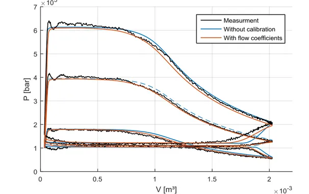
Figure 2-5 shows the comparison between the ideal, the theoretical and the actual indicator diagrams. In the ideal case, the pressures at the end of the expansion and the compression processes are equal to the exhaust and the supply pressures respectively and no pressure drop or other losses affect the expansion process. This case represents a fully isentropic evolution of the fluid through the machine. In practice, the
a b c Supply
Chapter 2: Piston expander and their use in Rankine cycle and Ericsson heat engines
22 pressure ratio rarely matches with internal built-in expansion and compression ratios leading to under- or over-expansion and compression losses. The theoretical diagram shows the effect of under-expansion and compression, which tends to decrease the area under the indicator diagram and thus the indicated power.
Figure 2-5: Comparison between ideal, theoretical and actual indicator diagram
Pressure drop
Pressure drop result from flow restrictions through the valves. Supply pressure drop tend to decrease the pressure at the beginning of expansion phase and exhaust pressure drop to increase the pressure during the compression process. Moreover, at the end of expansion and compression, the equalization of the pressure in case of under expansion and compression is not sudden as in the theoretical diagram. As shown in Figure 2-5, these effects deform the indicator diagram and reduce the indicated power. Pressure drops also tend to decrease the mass flow rate displaced by the expander.
Heat transfer
As the temperature of the fluid is different from the temperature of the cylinder wall and piston head, a heat exchange occurs. The wall temperature is lower than the fluid supply temperature (unless if the cylinder is heated by an external hot source in order to approach an isothermal expansion) leading to a cooling down of the fluid and then a possible increase in the mass flow rate. This supply cooling down can lead to condensation if vapor is used. Condensation of the vapor can reduce significantly the in-cylinder pressure and then reduce the power. During the exhaust process, the wall temperature can be either higher or lower than the fluid temperature and heating-up or cooling-down can occur. In the absence of condensation, heat transfer does not have significant impact on the indicated work and affect mostly the exhaust temperature.
23
Leakages
Leakages occur when a pressure difference is applied to a leakages path. Leakage paths result from clearances between mechanical parts of the expander and depend on the mechanical design. In piston expanders, fluid can leak along the supply valve from the admission manifold to the cylinder. As this leak flow enters the cylinder, it contributes to the indicated power but still constitutes a loss as the fluid is throttled before entering the cylinder. Another leakage path is clearance between the piston rings and the cylinder wall. This leakage flow leaves the cylinder and then tends to decreases the indicated power. Some fluid can also by-pass the cylinder through clearances such as along supply valves stems. Leakages increase the mass flow rate and thus decrease the specific work.
Figure 2-6: Main leakages paths
Mechanical friction losses
Friction losses appear between moving parts in contact. In piston expanders, the main friction forces appear in the piston-cylinder assembly, the bearings of the crank train or swash plate system and in the valve trains. The magnitude of the friction forces depends on the friction coefficient which depends on the lubrication regime. Three different types of regime of lubricated friction exist, according to the oil film thickness between the two sliding part: boundary, hydrodynamic and mixt. In boundary regime, the oil film is too small to prevent solid-to-solid contact between surfaces. In hydrodynamic regime, the oil film separates completely the two surfaces. The mixed regime is the transition between the boundary and hydrodynamic lubrication. These three regimes can be illustrated by the Stribeck diagram (see Figure 2-7) where the friction coefficient is plotted in terms of the dimensionless parameter 𝜇. 𝑈/𝜎, where 𝜇 is the dynamic viscosity of the lubricant, 𝑈 is the relative velocity of the two surfaces and 𝜎 is the load. In boundary regime, friction is higher and independent on the relative speed of the two surfaces while in hydrodynamic regime, the friction force increases with the speed. Friction losses depend also on the load applied to the moving parts and then on the pressure in the cylinder. However, in hydrodynamic regime, the friction power does not depend significantly on the load.
Chapter 2: Piston expander and their use in Rankine cycle and Ericsson heat engines
24
Figure 2-7: Stribeck diagram (Heywood 1988)
Figure 2-8 shows an ICE motored engine breakdown test results. The graphic shows the evolution of the different sources of mechanical losses in terms of engine speed. According to (Heywood 1988), the piston assembly accounts for 50% of total mechanical losses, the valve train for 25%, the crankshaft bearings for 10% and the auxiliaries for 15%.
25
2.3.2. Mass flow rate
The theoretical mass flow rate is the mass flow rate associated with the theoretical indicator diagram. Then, according to Figure 2-1, the mass entering into the cylinder is the difference between the masses at point 2 and point 6 or point 5 as the system is a closed system during step 5-6. The theoretical mass flow rate is then given by:
𝑀̇𝑡ℎ = 𝑛𝑐𝑦𝑙. 𝑁. (𝑉𝐼𝐶. 𝜌𝐼𝐶,𝑡ℎ− 𝑉𝐸𝐶. 𝜌𝑒𝑥) ( 2-4 )
where 𝑛𝑐𝑦𝑙 is the number of cylinders, 𝑁 the rotational speed and 𝜌𝐼𝐶,𝑡ℎ and 𝜌𝑒𝑥 the densities of the fluid at the end of the supply process and exhaust thermodynamic states. The state of the fluid at the end of the admission process differs from the one at the supply because of the mixing of the new fluid charge and the fluid remaining in the clearance volume.
As explained above, losses affect the theoretical mass flow rate. Indeed, pressure drops tend to decrease it while leakages and heat transfer tends to increase it. Actual mass flow rate entering the expander can be expressed by:
𝑀̇ = 𝑀̇𝑖𝑛+ 𝑀̇𝑙𝑒𝑎𝑘= 𝑛𝑐𝑦𝑙. 𝑁. (𝑉𝐼𝐶. 𝜌𝐼𝐶− 𝑉𝐼𝑂. 𝜌𝐼𝑂) + 𝑀̇𝑙𝑒𝑎𝑘 ( 2-5 ) where 𝑀̇𝑖𝑛 is the internal mass flow rate, 𝑀̇𝑙𝑒𝑎𝑘 the lumped leakage flow rate, 𝑉𝐼𝑂 is the inlet open volume and 𝜌𝐼𝐶 and 𝜌𝐼𝑂 the density of the fluid in the cylinder at inlet closing and opening volume and. 𝜌𝐼𝐶 differs from 𝜌𝐼𝐶,𝑡ℎ because of supply pressure drop and heat transfer.
2.3.3. Indicated and mechanical power
The indicated work is defined has the work delivered by the fluid to the piston. This indicated work is given by the area enclosed in the PV diagram. This area is obtained by integrating the pressure curve of the PV diagram:
𝑊𝑖𝑛= ∮ 𝑃. 𝑑𝑉 ( 2-6 )
The corresponding indicated power is given by the product of the rotational speed (in Hz) and the indicated work:
𝑊̇𝑖𝑛= 𝑁. 𝑊𝑖𝑛 ( 2-7 )
Considering the theoretical PV diagram (Figure 2-1), theoretical indicated work is the sum of the suction work, expansion work, discharge work and compression work. It can be expressed by:
𝑊𝑖𝑛,𝑡ℎ= 𝑃𝑠𝑢. (𝑉𝐼𝐶− 𝑉0) + 𝑉𝐼𝐶. 𝜌𝑠𝑢. (𝑢𝑠𝑢− 𝑢𝑖𝑛,𝑒𝑥𝑝) − 𝑃𝑒𝑥. (𝑉𝑇𝑜𝑡− 𝑉𝐸𝐶) − 𝑉𝐸𝐶. 𝜌𝐸𝐶. (𝑢𝑖𝑛,𝑐𝑝− 𝑢𝐸𝐶)
( 2-8 )
where 𝑢 is the internal specific energy and subscript 𝑖𝑛, 𝑒𝑥𝑝 and 𝑖𝑛, 𝑐𝑝 represent the state of the fluid at the end of the internal expansion and compression respectively.
Chapter 2: Piston expander and their use in Rankine cycle and Ericsson heat engines
26 In order to quantify the indicated work decrease caused by the irreversiblies, the diagram factor (in reference to the indicator diagram) is defined as the ratio between the actual indicated work and theoretical indicated work:
𝜖𝑖𝑛 = 𝑊̇𝑖𝑛 𝑊̇𝑖𝑛,𝑡ℎ
( 2-9 )
Due to friction losses, all the indicated power is not available at the expander shaft. The shaft power is obtained by substracting the mechanical losses:
𝑊̇𝑠ℎ = 𝑊̇𝑖𝑛− 𝑊̇𝑙𝑜𝑠𝑠,𝑚𝑒𝑐= 𝑁. 2. 𝜋. 𝑇𝑠ℎ ( 2-10 )
where 𝑇𝑠ℎis the shaft torque.
To quantify these mechanical losses, the mechanical efficiency is defined as:
𝜂𝑚 =𝑊̇𝑠ℎ 𝑊̇𝑖𝑛 = 𝑊̇𝑖𝑛−𝑊̇𝑙𝑜𝑠𝑠,𝑚𝑒𝑐 𝑊̇𝑖𝑛 ( 2-11 )
2.4. Performances indicators
2.4.1. Volumetric performance
As for volumetric compressor, the volumetric performance of positive displacement expander is evaluated with the ratio between the actual and theoretical mass flow rate (called filling factor):
𝜙 = 𝑀̇ 𝑀̇𝑡ℎ
( 2-12 )
However, unlike in compressors, the leakage flows is in the same direction as internal flow and tends to increase the total mass flow and then the filling factor. So, the effects of the leakages and of the pressure drops are antagonist. Moreover, supply cooling down can also lead to an increase in the entering fluid mass flow rate. These different antagonist effects make the analysis of the filling factor difficult. To better understand the separate effect of leakages, the filling factor can be disaggregated into two parts:
𝜙 = 𝑀̇ 𝑀̇𝑡ℎ= 𝑀̇ 𝑀̇𝑖𝑛. 𝑀̇𝑖𝑛 𝑀̇𝑡ℎ= 𝜙𝑙. 𝜙𝑖𝑛 ( 2-13 )
In this equation, 𝜙𝑙 is the leakage filling factor and quantifies the effect of the leakages. 𝜙𝑖𝑛 is the internal filling factor and quantifies the effect of supply pressure drop and heat transfer. The leakage filling factor is greater than one while the internal filling factor is smaller than unity if pressure drops are predominant.
2.4.2. Energy conversion efficiency
In order to assess the performance of expansion machine, the produced power is compared to the power produced for a reference fluid evolution in the same operating conditions (supply condition and exhaust pressure) and with the same mass flow rate. The reference evolution is an isentropic evolution (adiabatic
27 and reversible) and the ratio between the actual power and the isentropic power is defined as the isentropic efficiency. Considering the indicated power, the indicated isentropic efficiency is given by:
𝜖𝑠,𝑖𝑛 =𝑊̇𝑖𝑛 𝑊̇𝑠 = 𝑊̇𝑖𝑛 𝑀̇.(ℎ𝑠𝑢−ℎ𝑒𝑥,𝑠)= 𝑊̇𝑖𝑛 𝑀̇.Δℎ𝑠 ( 2-14 )
where ℎ𝑒𝑥,𝑠 is the specific enthalpy at the exhaust of the isentropic expansion. Alternatively, considering the shaft power, the shaft isentropic efficiency is:
𝜖𝑠,𝑠ℎ=𝑊̇𝑠ℎ 𝑊̇𝑠 = 𝑊̇𝑠ℎ 𝑊̇𝑖𝑛 𝑊̇𝑖𝑛 𝑀̇.Δℎ𝑠= 𝜂𝑚. 𝜖𝑠,𝑖𝑛 ( 2-15 )
As for the filling factor, the shaft isentropic efficiency can be disaggregated to assess the relative impact of each source of losses:
𝜖𝑠,𝑠ℎ= 𝑊̇̇𝑠ℎ 𝑚̇.Δℎ𝑠= 𝑊̇𝑠ℎ 𝑊̇𝑖𝑛 𝑊̇𝑖𝑛 𝑊̇𝑖𝑛,𝑡ℎ 𝑊̇𝑖𝑛,𝑡ℎ 𝑀̇𝑡ℎ.Δℎ𝑠 𝑀̇𝑡ℎ 𝑀̇𝑖𝑛 𝑀̇𝑖𝑛 𝑀̇ = 𝜂𝑚. 𝜖𝑖𝑛. 𝜖𝑠,𝑡ℎ. 1 𝜙𝑖𝑛. 1 𝜙𝑙 ( 2-16 )
All the factors of this decomposition have already been defined, except the theoretical isentropic efficiency 𝜖𝑠,𝑡ℎ, which quantifies the under or over expansion and compression losses. As explained above, the mechanical efficiency 𝜂𝑚 quantifies the mechanical losses and the diagram factor 𝜖𝑖𝑛 quantifies the impact of pressure and heat transfer losses on indicated work (and on indicated diagram, hence its name). The last two factors account for the impact of losses on the mass flow rate.
In equation ( 2-16 ), two terms account for pressure drops and heat transfer effect: diagram factor 𝜖𝑖𝑛 and internal filling factor 𝜙𝑖𝑛. Then, the effect of pressure drop and heat transfer on isentropic efficiency is given by: 𝜖𝑠𝑝,𝑖𝑛=𝜙𝜖𝑖𝑛 𝑖𝑛 = 𝑊̇𝑖𝑛 𝑀̇𝑖𝑛. 𝑀̇𝑡ℎ 𝑊̇𝑖𝑛,𝑡ℎ= 𝑤𝑖𝑛 𝑤𝑖𝑛,𝑡ℎ ( 2-17 )
and corresponds to the ratio between indicated and theoretical specific works and it will be called “specific diagram factor”. It is interesting to note that, as internal filling factor is more often smaller than unity, it tends to increase the isentropic efficiency. However, this increase does not come from an improvement but from the reduction of the mass flow rate used to compute the isentropic efficiency.
This disaggregation allows the evaluation of the impact of the different source of losses and the comparison of different volumetric expanders. The values of these losses factors can be obtained by experimentation and/or modeling. Theoretical isentropic efficiency is always determined by modeling. Mechanical efficiency and diagram factor can be measured if in-cylinder pressure measurements are available to compute indicated work. Finally, as leakages are difficult to measure, it is more convenient to simulate them to obtain leakage and internal filling factor.
2.4.3. Compactness
In order to quantify the compactness of a piston expander, the delivered power can be divided by the displaced volume. As shown in equation ( 2-18 ), the compactness is the product of the rotational speed, of the diagram factor and of the ratio between the theoretical indicated work and the displaced volume.
Chapter 2: Piston expander and their use in Rankine cycle and Ericsson heat engines
28 This last factor has the dimensional unit of a pressure and is called “theoretical indicated mean effective pressure”. Regarding the equation ( 2-18 ), the diagram factor can be considered as a compactness efficiency. 𝐶𝑛𝑒𝑠𝑠 =𝑊̇𝑠ℎ 𝑉𝑡𝑜𝑡 = 𝑊𝑠ℎ 𝑊𝑖𝑛 𝑊𝑖𝑛 𝑊𝑖𝑛,𝑡ℎ. 𝑊𝑖𝑛,𝑡ℎ 𝑉𝑡𝑜𝑡 . 𝑁 = 𝜂𝑚. 𝜖𝑖𝑛. 𝑖𝑚𝑒𝑝𝑡ℎ. 𝑁 = 𝜂𝑚. 𝑖𝑚𝑒𝑝. 𝑁 = 𝑠𝑚𝑒𝑝. 𝑁 ( 2-18 )
As for the theoretical indicated mean effective pressure, the “indicated mean effective pressure” and “shaft mean effective pressure” can be defined:
𝑠𝑚𝑒𝑝 =𝑊𝑠ℎ
𝑉𝑡𝑜𝑡 = 𝜂𝑚. 𝑖𝑚𝑒𝑝 = 𝜂𝑚. 𝜖𝑖𝑛. 𝑖𝑚𝑒𝑝𝑡ℎ
( 2-19 )
Considering equations ( 2-18 ) and ( 2-19 ) , the compactness can be expressed as:
𝐶𝑛𝑒𝑠𝑠 = 𝜂𝑚. 𝑖𝑚𝑒𝑝. 𝑁 = 𝑠𝑚𝑒𝑝. 𝑁 ( 2-20 )
In the same way, mechanical losses is sometime expressed as “friction mean effective pressure”:
𝑓𝑚𝑒𝑝 =𝑊𝑙𝑜𝑠𝑠
𝑉𝑡𝑜𝑡 ( 2-21 )
3. Ericsson engine
3.1. Working principle
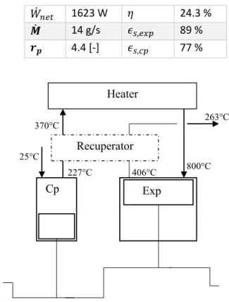
The Ericsson engine is an externally heated piston engine. The working fluid is generally air so it is classified as a hot air engine. A schematic representation of an Ericsson engine is shown in Figure 2-9. It shows that the fluid enters the compression cylinder (Cp) where it is compressed. Then, the fluid exits the compressor to enter the heater. There, it receives an amount of thermal energy and its temperature rises. Finally, the fluid expands into the expander (Exp) to produce mechanical energy. Improvement of the engine can be made by adding a recuperator that recovers the heat available at the exhaust of the expander to preheat the fluid before it enters the heater. It is also possible to introduce a heat exchanger to cool the fluid that leaves the expander before driving it to the compressor, so that the engine works in a closed loop.
29
Figure 2-9: Schematic representation of an Ericsson engine
Contrary to what its name suggests, the best theoretical cycle to describe an Ericsson engine is the Brayton cycle and not the Ericsson cycle. Indeed, the Ericsson cycle is made up of two isobaric and two isothermal processes (Figure 2-10). However, in an Ericsson engine, the heat transfers between the heat source/sink and the working fluid take place in dedicated heat exchangers and not in the cylinders. Then, the Brayton cycle, consisting of two isobaric and two isentropic processes, used to describe gas turbines, is more suitable. In this sense, the Ericsson engine is a gas turbine where turbomachines are replaced by volumetric engines (Bonnet, Alaphilippe, and Stouffs 2005).
Heater
Recuperator
Chapter 2: Piston expander and their use in Rankine cycle and Ericsson heat engines
30
Figure 2-10: T-s diagram of ideal Ercisson (up) and Brayton (down) cycle
For this type of engine, the pressure ratio is defined as the ratio between the pressure in the heater and the engine supply/exhaust pressure. The temperature ratio is defined as the ratio between the temperature at the exhaust of the heater and the temperature at the supply of the engine.
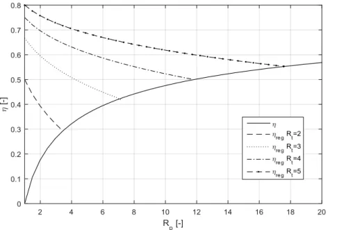
Figure 2-11 shows the thermal efficiency of the simple ideal Brayton cycle and of the ideal regenerative cycle in terms of pressure ratio and for different temperature ratios. The simple cycle efficiency is independent on the temperature ratio and increases with the pressure ratio. The ideal regenerative cycle efficiency is maximal for a pressure equal to one, but the delivered power is null for this pressure ratio and decreases until reaching the simple cycle efficiency. At this point, the expander exhaust temperature is
31 equal to the compressor exhaust temperature and the recuperator becomes pointless. The higher the temperature ratio the higher the regenerative efficiency.
Figure 2-11: Cycle efficiency of the ideal Brayton cycle in terms of pressure ratio for different temperature ratios
However, the compression and the expansion processes are not isentropic in an actual Brayton cycle. Therefore the cycle efficiency is affected by the isentropic efficiency of the compressor and the expander. Figure 2-12 shows regenerative and simple cycle efficiencies in terms of pressure ratio and for different temperature ratios. It can be seen that, when the compression and the expansion are not isentropic:
there is an optimum pressure ratio for both efficiencies
the optimal pressure ratio is lower for the regenerative cycle efficiency
both efficiencies increase with temperature ratio
The efficiency of the actual Brayton cycle is much lower than the one of an ideal cycle and is very sensitive to the compressor/expander isentropic efficiency. Indeed, for an expander supply temperature of 800°C the optimal regenerative efficiency drops from 30% to 5% when the isentropic efficiency drops from 80% to 60%.
Chapter 2: Piston expander and their use in Rankine cycle and Ericsson heat engines
32
Figure 2-12: Efficiency of the Brayton cycle in term of pressure, with compression and expansion isentropic efficiency of 0.8 (up) and 0.6 (down) and for different expander supply temperature
3.2. Previous work on Ericsson engine
The first Ericsson engine was designed and built by John Ericsson in 1833. In 1853 he built another engine with a power of 220 kW to propel a ship. Then, J. Ericsson designed a smaller engine of 600W, which was the first mass-produced engine with 3000 pieces produced between 1855 and 1860. Later, steam engines and ICE replaced hot air engines. However, the Ericsson engine has recently regained interest for application such as biomass cogeneration.
Blank and Wu (1996) (Blank and Wu 1998) proposed to use an Ericsson engine based on theoretical Ericsson cycle with perfect regeneration and with a pressure ratio of 2.64. The engine would be used with
33 heat sources of temperatures varying between 630°C and 1230°C or in space application, with radiant heat exchanges with the sun as heat source and outer space as heat sink.
Brzeski and Kazimierski (2001) tested an Ericsson engine (denoted as externally heated valve engine (EHVE)) with cylinder of 432.8 cm³ for both compressor and expander (ratio=1). The engine run in a closed cycle, higher temperature is between 550 and 800°C, high and low pressures are around 26 bar and 8 bar respectively and rotational speed ranges from 360 to 720 RPM. Two small volumes (about the volume of the expansion cylinder) heaters are used alternatively. This system allows higher cut-off but needs very high heat transfers rate. The engine had just enough power to overcome frictions because of too low heat flow. Then, in the continuity of this work, Wojewoda and Kazimierski (2010) proposed to use one larger heater (3 to 5 times the volume of the expansion cylinder) with recirculating blower to improve heat transfer, shorter cut-off and a ratio between the volume of the expander and the volume of the compressor larger than one. The total cylinders volume of the expander and compressor are 𝑉𝑡𝑜𝑡,𝑒𝑥𝑝=428 cm³ and 𝑉𝑡𝑜𝑡,𝑐𝑝=323 cm³ respectively (ratio=1.33). The simulation results show high and low pressures of around 95 bar and 16 bar respectively with an operating temperature around 900°C. The study concludes that simulated performances are equivalent to those that would be obtained with a Stirling engine. Stouffs (2002) considered using Ericsson engine to valorize energy sources such as biomass, biogas, hot gases and, in particular, syngas from waste thermolysis, not adapted to be burnt into ICE. The authors proposed to use double acting piston expander and compressor and to connect in series the volumes of the compressor to achieve a multistage compression. A fast design lead to a 100 kW engine with total expander swept volume of 0.145 m³ and compressor swept volume of 0.0627 m³ and 0.0278 m³ (ratio of 2.3). Maximal values of 800°C, 6 bar, 500 RPM and 8 m/s as high temperature, high pressure, rotational speed and mean piston speed respectively are considered. The system is expected to produce 113 kW of mechanical power.
Bell and Partridge (2003) proposed to use an Ericsson engine for domestic CHP (1-5 kW). The influence of the swept volume ratio (ratio between swept volume of expander and compressor of the engine), pressure ratio, pressure drop and leakages on thermal efficiency are used to give guideline for the design. A maximum operating temperature of 1000°C is considered and pressure ratio ranges from 6 to 8. In the continuity of the work of Bell et al., Allen (2008) adapted a four cylinders 2.5 L diesel engine to work as an Ericsson engine by modifying the cylinders heads. Two cylinders were used for the expander and one for the compressor. During the experimental campaign, several modification were made following different issues such as unstable combustion, damage to valve gear, investigation on valve timing … Pressure and temperature up to 4 bar and 870°C were achieved but the engine only self-sustained and no net power was produced. The author pointed out the importance of low friction for good efficiency of the Ericsson engine and to maximize the IMEP to increase mechanical efficiency. Because of the lower operating pressure compared to ICE, the authors proposed to use a single gas ring and an oil control ring.
Several other studies considered the use of Ericsson engine for domestic CHP. Moss, Roskilly, and Nanda (2005) proposed to directly burn natural gases in the air used as working fluid for CHP of 5 kW. The authors preconized a pressure ratio of 7.5, a rotational speed of 1000 RPM, leading to expander and compressor cylinders capacities of 4650 cm3 and 1770 cm³ respectively (ratio=2.6). Bonnet, Alaphilippe, and Stouffs (2005) performed parametric study on heat exchanger efficiency and energy, exergetic and
Chapter 2: Piston expander and their use in Rankine cycle and Ericsson heat engines
34 cost analysis on a 10 kW CHP. A maximal rotational speed of 1000 RPM and a mean piston speed of 8 m/s are considered. The expander swept volume is 2200 cm³ and the compressor swept volume is 957 cm³ (ratio=2.3). The expander inlet pressure and temperature are 6 bar and 800°C respectively. The authors concluded that a profitability of the system is possible considering the price of the French energy suppliers. Mikalsen and Roskilly (2012) proposed to use free piston engine for a 4.5 kW CHP. The swept volumes of the expander and compressor are 773 cm³ and 386 cm³ (ratio=2). Expander and compressor are directly connected and electricity is produced with a linear generator. Operating temperature and pressure are 800°C and 5.9 bar.Creyx et al. (2013) studied the influence of incomplete expansion and compression on the energetic performances of an Ericsson engine used for micro-CHP with operating temperature and pressure ranging between 400-650°C and 5-8 bar. Later, the authors presented a test bench of expansion part and biomass furnace (Creyx 2015). The expansion part of the Ericsson engine is made with a 160 cm³ mono-cylinder expander with adapted distribution system. The engine is designed to run with the operating condition aforementioned and for rotational speed of 100-1400 RPM. In the publication, only mechanical losses are assessed by electrically driving the engine and no test under operating conditions is performed. Lontsi et al. (2013) performed dynamic simulation for a 1.6 kW CHP. Swept volumes are 226 cm³ for the compressor and 425 m³ for the expander (ratio 1.88). Pressure ratio of 4, temperature of 800°C and rotational speed of 480 RPM are considered.
Alaphilippe, Bonnet, and Stouffs (2007) considered the coupling of a parabolic trough solar concentrator and a 733W Ericsson engine in order to convert solar energy into electricity. A pressure ratio of 3 is considered to maximize the global efficiency of the system and a maximal operating temperature of 722°C is expected.
Touré (2010) tested a 650 cm³ expander prototype fed by a commercial compressor. Operating temperature during the test varied from 300°C to 500°C, pressure ratio was about 3.5 and maximal 950 RPM corresponding to a mean piston speed of 4.1 m/s. The expander produced between 0.3 and 1kW with a mechanical efficiency of 87% independent of the speed and isentropic efficiency varied from 40% to 75%. In the continuity of this work, Fula, Stouffs, and Sierra (2013) proposed a dynamic model and the study of the influence on the in-cylinder heat transfer. Simulation showed that heat transfers affect exhaust temperatures but not so much the performance of the compressor and expander.
Galindo, Serrano, et al. (2015) studied the possibility of a WHR system for a car with a Brayton cycle. Piston compressor and expander were selected because turbines or roots machines would show a too high rotational speed.
In conclusion, the Ericsson engine is generally considered because of its externally heated feature leading to the possibility of using a large panel of fuels. The different theoretical and experimental studies are summarized in Table 2-1. The major application considered for this hot air engine is micro-CHP. Operating temperature ranges between 300°C and 1000°C but is more often about 800°C, the pressure ratio is between 3 and 8 and low rotational speeds seem to be preferred (500-1500 RPM). Most of the studies consider an open cycle and a volume ratio around 2. Among the 14 studies, only 3 report experimental results and none of them relates positive net-power. This lack of experimental testing was the main motivation to develop and test a prototype (see Chapter 4).
35
Table 2-1: Summary of the Ericsson engine literature review.
References Application Cycle type 𝑽𝒆𝒙𝒑,𝑽𝒄𝒑 [cm³], volume ratio Operating temperature, pressure ratio, speed
Power Nature of the study (Blank and Wu 1996) Ericsson regenerative closed cycle / 2.64 / Theoretical (Brzeski and Kazimierski 2001) / Closed cycle 432.8 432.8 1 550-800°C 3.25 360-720 RPM Self-sustain Experimental (Wojewoda and Kazimierski 2010) / Closed cycle 428 323 1.33 900°C 6 1000-3000 RPM / Theoretical (Stouffs 2002) Open recuperation cycle Thermolysis syngas combustion 145e3 62e3 2.3 800°C 6 500 RPM 113 kW Theoretical
(Bell and Partridge 2003) Open recuperation cycle, internal combustion CHP 1000°C 6-8 / 1-5 kW Theoretical (Allen 2008) Open cycle, Internal combustion CHP 1250 625 2 870°C 4 / Self-sustain Experimental
(Moss, Roskilly, and Nanda 2005) Open recuperation cycle, internal combustion CHP 4650 1770 2.6 / 7.5 1000 RPM 5 kW Theoretical (Bonnet, Alaphilippe, and Stouffs 2005) Open recuperation cycle CHP 2200 957 2.3 800°C 6 1000 RPM 10 kW Theoretical (Mikalsen and Roskilly 2012) Open recuperation cycle, internal combustion CHP 773 386 2 800°C 5.9 4.5 kW Theoretical
(Creyx et al. 2013) Open cycle, CHP 160 / / 400-650°C 4 100-1400 RPM Theoretical
(Lontsi et al. 2013) Open cycle CHP 425 226 1.88 800 °C 4 480 RPM 1.6 kW Theoretical
Chapter 2: Piston expander and their use in Rankine cycle and Ericsson heat engines
36
(Alaphilippe, Bonnet, and Stouffs 2007) Open recuperation cycle Solar power 722 °C 3 0.73 kW Theoretical
(Touré 2010) Only expander / 650 cm³ / / 300-500 °C 3.5 500-950 RPM 1 kW Expander only! Experimental (Galindo, Serrano, et al. 2015) / WHR in vehicle Theoretical
4. Rankine cycle
4.1. Working principle
The Rankine cycle is a power cycle using the expansion of vapor to produce power. Figure 2-13 shows the temperature-entropy (T-s) diagram of a Rankine cycle. It is shown that the fluid is first in a liquid state and is pumped from the low pressure condenser to the high pressure evaporator. In the evaporator, the pressurized fluid is heated up, evaporated and then superheated. Then, the fluid expands in the expansion device where it produces the useful power. Afterward, the fluid is condensed in the condenser and the sub-cooled liquid is pumped back to the evaporator.
In general, Rankine cycle refers to vapor cycle using water as working fluid while Organic Rankine Cycle (ORC) uses fluid such as refrigerant or hydrocarbon fluid (organic fluids) showing lower normal boiling points. Unlike water, some organic fluids are “dry”, i.e. the slope of their vapor saturation curve on the T-s diagram iT-s poT-sitive. ThiT-s property enableT-s, aT-s in Bratyon cycle, the uT-se of a recuperator to recover the heat still available at the outlet of the expander to preheat the liquid before it enters the evaporator.
37 During the recent years, a particular attention has been paid on expansion machines used in small scale ORC systems. Indeed, the expander plays a key role in terms of system efficiency and other components (pump and heat exchangers) are already mature technologies. While turbines are used in large-scale Rankine systems, volumetric expanders are often preferred for low-scale applications (<25 kW), because of their low rotational speed and their ability to ingest liquid and handle high pressure ratios. Among other technologies of positive displacement machines such as scroll or screw expanders, piston expanders are more and more considered in the literature.
4.2. Previous work on the use of piston expander in (Organic) Rankine cycle
Using piston expanders in (O)RC has been recently considered in many applications. The present literature review is organized in according of these applications.
4.2.1. Steam cars
In the 70’s, Rankine cycle heat engines were reconsidered for low exhaust emission passenger car propulsion, because standards became stricter. The Rankine cycle, often call “steam engine” in this field, allowed low emission of CO, HC and NOx because combustion process is continuous and can be carefully controlled (Hoagland, Demler, and Gerstmann 1974). Reciprocating expander was considered because of the better efficiency for the ranging speed and favorable torque characteristic for automotive applications compared to turbines. A car equipped with a steam engine was tested by GM (Vickers et al. 1970) and the Scientific Energy Systems Corporation (SES) (Technologie Assesment and Evaluation Branch 1974). The SES expander was 2200 cm³ uniflow expander with two in-series cam-actuated poppet valves admission system allowing variable cut-off to control the load. The expander was fed with steam at 69 bar and 538°C and produced a maximum power of 100 kW. Maximum isentropic efficiency was about 60%.
In the context of the steam engine passenger car, Demler (1976) studied the influence of cut-off, recompression ratio, supply pressure drop, heat transfer and mechanical losses on piston expander performance. According to the author, almost all volumetric expanders for car applications were piston expanders, but differ between uniflow or counter flow and constant or variable cut-off.
4.2.2. Expansion valve in CO2 cycle
According to Huff and Radermacher (2003), since 1990, several studies had considered the use of expanders to replace the expansion valves in CO2 refrigeration cycle systems. Simulation showed that gas-wall heat transfer had no influence on the performance for this application. Comparison with scroll machines showed that, for this application where pressure difference is very large (e.g. 𝑃𝑠𝑢=85 bar and 𝑃𝑒𝑥=41 bar), the scroll is more dependent on the leakage gap size because of the larger sealing length. The authors reported two experimental studies performed by Heyl and Quack (2000) and Maurer and Zinn (2000) for this application, where the expanders showed isentropic efficiencies of 51% and 50% respectively.
Baek and al. (Baek, Groll, and Lawless 2002) (Baek, Groll, and Lawless 2005) tested prototypes for CO2 trans-critical compression cycle. The piston expander allows the recovering of the work from expansion and the minimization of the entropy creation during the process. The expander was made off a bi-cylinder