This is an author-deposited version published in:
http://oatao.univ-toulouse.fr/
Eprints ID: 10034
To link to this article: DOI: 10.1109/ANTEM.2012.6262393
URL:
http://dx.doi.org/10.1109/ANTEM.2012.6262393
To cite this version:
Pascaud, Romain and Legay, Hervé and Calmettes,
Thibaud Compact dual-polarized VHF microstrip antenna for satellite
applications. (2012) In: 15th International symposium of Antenna
Technology and Applied Electromagnetics (ANTEM), 2012 15th
International Symposium on, 25 June 2012 - 28 June 2012 (Toulouse,
France).
O
pen
A
rchive
T
oulouse
A
rchive
O
uverte (
OATAO
)
OATAO is an open access repository that collects the work of Toulouse researchers and
makes it freely available over the web where possible.
Any correspondence concerning this service should be sent to the repository
administrator:
[email protected]
Compact Dual-Polarized VHF Microstrip Antenna
for Satellite Applications
Romain Pascaud
Universit´e de Toulouse : ISAE, DEOS, Toulouse, FRANCE
Email: [email protected]
Herv´e Legay and Thibaud Calmettes
Thales Alenia Space, Toulouse, FRANCE
Abstract—This paper presents the design of a compact dual-polarized VHF microstrip antenna for modern small satellites. It consists of a slot-loaded annular-ring microstrip antenna printed on a light substrate to reduce its mass. A simple matching circuit is proposed to match the high input impedance of this antenna while enabling the generation of a dual linear-polarization. The size of the proposed design is finally equal to 450 mm at 161 MHz, i.e.λ0/4.
I. INTRODUCTION
To reduce the mission cost and development time within the space industry, modern small satellites are increasingly used [1]. These compact satellites are well adapted for various applications such as Earth observation, telecommunications, or military applications. However, they often require multi-ple radio-communication systems that must accordingly be reduced in size. If the sizes of electronics needed for satellite applications have decreased substantially, the design of com-pact antennas remains a challenge [2]. Indeed, to be efficient, the size of an antenna should be equal, or larger than, half a wavelength, which can lead to very large antennas, especially in the VHF and UHF bands (wavelength between 30 cm and 10 m). The miniaturization of antennas is still possible, but at the expense of their bandwidth, gain, and polarization purity. Among the basic space radiators (monopoles, helices, reflec-tors . . . ), microstrip antennas exhibit some interesting features when considering their integration on small satellites. Indeed, due to their low-profile geometry, they can be flush-mounted in the satellite’s body, or even deployed in an array configuration to increase the overall antenna gain. However, microstrip antennas may remain bulky for low frequency applications.
Several miniaturization techniques have been proposed to reduce the size of microstrip antennas [2]. A classical tech-nique consists in loading the antenna with lumped-elements or short circuits. However, cross-polarization characteristics often suffer when loaded with parasitic elements. One can also use a dielectric substrate with a high permittivity in order to reduce the guided wavelength, and therefore the size of the antenna. Nevertheless, such a solution usually leads to heavier antennas that may substantially increase the mass of the satellite, and then the mission cost. Another way to make a microstrip antenna smaller is to modify its shape, for example by inserting slots to meander the currents.
In this paper, we proposed a compact dual-polarized VHF microstrip antenna design working at 161 MHz and suitable for modern small satellites. This antenna is based on several modifications of an annular-ring microstrip antenna (ARMA). The first section deals with the miniaturization of such an ARMA by loading it with multiple slots. Then, a technique to match the high input impedance of the small slot-loaded ARMA to a 50 Ω coaxial connector is proposed. Finally, a way to implement a dual linear-polarization is presented.
II. ANNULAR-RINGMICROSTRIPANTENNA
MINIATURIZATION
A. Conventional Annular-Ring Microstrip Antenna
The well-known ARMA has the advantage of being intrinsi-cally smaller than the square and circular microstrip antennas. Nevertheless, its larger dimension (i.e. its outer diameter) remains important at the chosen frequency of 161 MHz, and efficient miniaturization techniques must be implemented.
Due to the requirements of light and low-profile microstrip antennas, a 30 mm thick, low-loss, and light dielectric sub-strate has been considered. Unfortunately, such a light material has a small relative dielectric permittivity ǫr equal to 1.07, which does not contribute to the size reduction of the ARMA. Thus, considering a classical ARMA with an outer radius b equal to 225 mm (i.e. an outer diameter 2b equal to λ0/4 at 161 MHz) and an inner radiusa equal to 112.5 mm, we obtain a simulated resonant frequency at 278 MHz for the TM11 mode. Note that it is not possible to match the TM11 mode of the ARMA using a 50 Ω coaxial probe directly connected to the ring through the ground plane [3]. As a result, the resonant frequency of the TM11 mode has been determined by observing the complex input impedance of the antenna. B. Slot-Loaded Annular-Ring Microstrip Antenna
One way to reduce the resonant frequency of the ARMA, is to introduce multiple slots at its inner and outer periphery [4], [5]. As shown in Fig. 1 and Fig. 2, various geometries are possible depending on the number of slots Nslot, the slot length Lslot and the slot width Wslot. For instance, Fig. 1 presents several slot-loaded ARMA geometries for different number of slots Nslot, while Fig. 2 focuses on the variation of the slot length Lslot for a given number of slotsNslot.
(a) Nslot= 4 (b) Nslot= 8
(c) Nslot= 16 (d) Nslot= 32
Fig. 1. Slot-loaded ARMA geometries as a function of the number of slots Nslot(a = 112.5 mm, b = 225 mm, Lslot= 60 mm, and Wslot= 10 mm)
(a) Lslot= 0 mm (b) Lslot= 30 mm
(c) Lslot= 60 mm (d) Lslot= 100 mm
Fig. 2. Slot-loaded ARMA geometries as a function of the slot length Lslot
(a = 112.5 mm, b = 225 mm, Nslot= 32, and Wslot= 10 mm)
Fig. 3. Simulated resonant frequency of the slot-loaded ARMA as a function of the number of slots Nslotand the slot length Lslot (a = 112.5 mm,
b = 225 mm, and Wslot= 10 mm)
In Fig. 3, one can see the simulated resonant frequency of the slot-loaded ARMA as a function of the number of slots Nslot and the slot length Lslot. As expected, the resonant frequency of the ARMA reduces when slots are introduced. For a given number of slots Nslot, increasing the slot length Lslot leads to a reduction of the resonant frequency. For a given slot length Lslot, increasing the number of slots Nslot also leads to a reduction of the resonant frequency. Note that the slot width Wslot can be increased as well to reduce the resonant frequency.
Finally, a slot-loaded ARMA with a = 112.5 mm, b = 225 mm, Nslot = 32, Lslot = 75 mm, and Wslot = 10 mm exhibits a resonance at 161 MHz for the T M11 mode. Nevertheless, such a design still presents a very high input impedance that makes it hard to match with a 50 Ω coaxial probe through the ground plane.
III. IMPEDANCEMATCHING OF THESLOT-LOADED
ANNULAR-RINGMICROSTRIPANTENNA
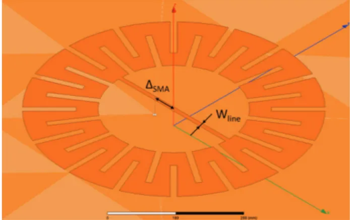
One solution to match a slot-loaded ARMA using a 50 Ω coaxial probe through the ground plane is to introduce a microstrip transmission line in its center [6]–[8]. As shown in Fig. 4, both ends of this microstrip transmission line are con-nected to the inner periphery of the annular-ring. Therefore, the coaxial probe can be moved away from the annular-ring to find the position where the input impedance is equal to 50 Ω on the microstrip transmission line. Finally, one can match the very high input impedance of the slot-loaded ARMA to the 50 Ω coaxial probe by varying the microstrip transmission line widthWlineand the position of the coaxial probe ∆SM A relative to the center of the annular-ring. However, it is important to mention that adding a microstrip transmission line in the center of the slot-loaded ARMA tends to increase its resonant frequency. Thus, additional slots are required to obtain the desired resonant frequency.
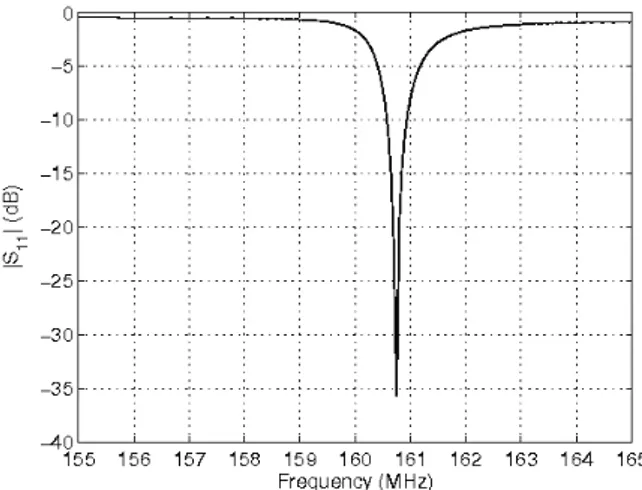
Fig. 5 presents the magnitude of the simulated reflection coefficient|S11| as a function of the frequency for a matched slot-loaded ARMA (a = 112.5 mm, b = 225 mm, Nslot= 40, Lslot = 100 mm, Wslot = 7.5 mm, Wline = 4.5 mm, and
Fig. 4. Geometry of the slot-loaded ARMA with a microstrip transmission line for impedance matching
Fig. 5. Magnitude of the simulated reflection coefficient|S11| as a function
of the frequency for the matched slot-loaded ARMA (a = 112.5 mm, b = 225 mm, Nslot = 40, Lslot = 100 mm, Wslot = 7.5 mm, Wline =
4.5 mm, and ∆SM A= 15 mm)
Fig. 6. Geometry of the single probe-fed dual-polarized slot-loaded ARMA
∆SM A = 15 mm). We observe a good impedance matching at 160.77 MHz with a minimum reflection coefficient|S11| = −36 dB. The relative bandwidth is small since it is equal to 0.07 % at -20 dB, but as it is well-known, electrically small antennas have high quality factors that reduce the maximum attainable bandwidth [9].
IV. DUALLINEAR-POLARIZATION OF THESLOT-LOADED
ANNULAR-RINGMICROSTRIPANTENNA
The impedance matching technique proposed in the previous section has the significant advantage of allowing the slot-loaded ARMA to achieve a dual-linear polarization radiation. Actually, as shown in Fig. 6, two orthogonal TM11 modes can be excited at the same frequency using two orthogonal microstrip transmission lines (i.e. a cross microstrip transmis-sion line geometry) associated with two orthogonal coaxial probes. Each linear polarization is then generated using a single coaxial probe, which means a total of two probes for a dual linearly-polarized antenna.
Fig. 7 shows the simulated antenna gain in the E-plane for the single probe-fed dual-polarized slot-loaded ARMA
Fig. 7. Simulated antenna gain in the E-plane for the single probe-fed dual-polarized slot-loaded ARMA (a = 112.5 mm, b = 225 mm, Nslot= 40,
Lslot = 100 mm, Wslot= 7.5 mm, Wline = 4.5 mm, and ∆SM A =
15 mm)
presented in Fig. 6. An asymmetric pattern is observed for the co-polarization due to the probe leakage radiation [10]. Besides, we note a significant cross-polarization level that is only 10 dB below the peak co-polarization level. The high level of cross-polarization is mostly caused by the dissymme-try of the feeding network of the antenna as well as the mutual coupling between the two orthogonal probes.
To obtain a symmetric pattern for the co-polarization and reduce at the same time the cross-polarization level, a dual-probe feeding technique is implemented [10]. Considering a single linear polarization operation, the dual-probe feeding technique consists in adding a second coaxial probe which is symmetrically located with respect to the center of the cross-microstrip line to the first coaxial probe. The excitation of this second probe is of equal magnitude but opposite phase to that of the first one. Therefore, the leakage radiation from the second probe is out of phase with that of the first probe, and thus the two cancel. As shown in Fig. 8, two coaxial probes are used for each linear polarization, i.e. a total of four coaxial probes in the case of a dual-linear polarization operation. After optimization, we obtain the following dimensions for the dual probe-fed dual-polarized slot-loaded ARMA: a = 112.5 mm, b = 225 mm, Nslot= 40, Lslot= 100 mm,Wslot= 7.5 mm, Wline= 6.5 mm, and ∆SM A= 9.5 mm.
In Fig. 9, it can be found that the simulated resonant frequency of the dual probe-fed dual-polarized slot-loaded ARMA is close to 161 MHz, and its relative bandwidth is equal to 0.07 % at -20 dB. Note that the active S-parameters have to be considered in that case.
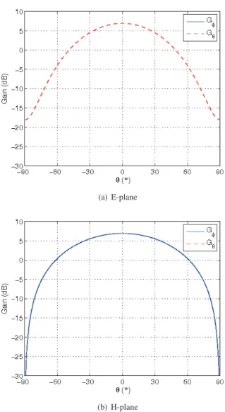
Fig. 10 presents the simulated antenna gain in the E-plane and in the H-plane. We now observe a symmetric pattern for the co-polarization as well as a strong reduction of the cross-polarization level in both planes.
Fig. 8. Geometry of the dual probe-fed dual-polarized slot-loaded ARMA
Fig. 9. Magnitude of the simulated active S-parameters as a function of the frequency for the dual probe-fed dual-polarized slot-loaded ARMA (a = 112.5 mm, b = 225 mm, Nslot= 40, Lslot= 100 mm, Wslot= 7.5 mm,
Wline= 6.5 mm, and ∆SM A= 9.5 mm)
V. CONCLUSION
A compact dual-polarized VHF microstrip antenna for mod-ern small satellites has been presented. It is based on several modifications of an annular-ring microstrip antenna that has been printed on a light substrate to reduce its mass. The miniaturization of the antenna has been performed by inserting multiple slots in its periphery. A simple matching circuit has also been proposed to match the high input impedance of this antenna while enabling the generation of a dual linear-polarization. Results have shown a reduction of the resonant frequency by a factor of 1.73 while keeping good radiation properties.
Future work will focus on the design of a compact mi-crostrip feeding network beneath the ground plane of the antenna to achieve the required amplitude and phase for the four probes.
REFERENCES
[1] S. Gao et al., “Antennas for modern satellites,” IEEE Antennas and Propagation Magazine, vol. 51, n. 4, pp. 40-56, August 2009.
[2] A. K. Skrivervik, J.-F. Z¨urcher, O. Staub, and J. R. Mosig, “PCS antenna design: the challenge of miniaturization,” IEEE Antennas and Propagation Magazine, vol. 43, n. 4, pp. 12-27, August 2001.
(a) E-plane
(b) H-plane
Fig. 10. Simulated antenna gain for the dual probe-fed dual-polarized slot-loaded ARMA (a = 112.5 mm, b = 225 mm, Nslot = 40, Lslot =
100 mm, Wslot= 7.5 mm, Wline= 6.5 mm, and ∆SM A= 9.5 mm)
[3] J. S. Dahele and K. F. Lee, “Characteristics of annular-ring microstrip antenna,” Electronics Letters, vol. 18, n. 24, pp. 1051-1052, November 1982.
[4] H. Legay, T. Rostan, F. Croq, and M. Gomez-Henri, “Antenne miniature r´esonnante de type microruban de forme annulaire,” Patent EP0860894. [5] G. J. K. Moernaut and G. A. E. Vandenbosch, “Size reduced meander line annular ring microstrip antenna,” Electronics Letters, vol. 40, n. 23, pp. 1463-1464, November 2004.
[6] W.-S. Chen, C.-K. Wu, and K.-L. Wong, “Square-ring microstrip antenna with a cross strip for compact circular polarization operation,” IEEE Transactions on Antennas and Propagation, vol. 47, n. 10, pp. 1566-1568, October 1999.
[7] N. C. Karmakar and S. K. Padhi, “Study of electrically small printed chakra (wheel) antenna,” Electronics Letters, vol. 37, n. 5, pp. 269-271, March 2001.
[8] J.-S. Row, “Dual-frequency circularly polarised annular-ring microstrip antenna,” Electronics Letters, vol. 40, n. 3, pp. 153-154, February 2004. [9] J. L. Volakis, C.-C. Chen, and K. Fujimoto, Small Antennas:
Miniatur-ization, Techniques & Applications, Mc Graw Hill, 2010.
[10] A. Petosa, A. Ittipiboon, and N. Gagnon, “Suppression of unwanted probe radiation in wideband probe-fed microstrip patches,” Electronics Letters, vol. 35, n. 5, pp. 355-357, March 1999.