Any correspondence concerning this service should be sent to the repository administrator:
staff-oatao@inp-toulouse.fr
O
pen
A
rchive
T
oulouse
A
rchive
O
uverte (
OATAO
)
OATAO is an open access repository that collects the work of Toulouse researchers
and makes it freely available over the web where possible.
This is an author -deposited version published in: http://oatao.univ-toulouse.fr/
Eprints ID: 3827
To link to this article: DOI:10.1016/j.matchemphys.2009.12.016
URL:
http://dx.doi.org/10.1016/j.matchemphys.2009.12.016
To cite this document
: Goueffon, Yann and Arurault, Laurent and Fontorbes, Sandra and
Mabru, Catherine and Tonon, Claire and Guigue, Pascale ( 2010) Chemical
characteristics, mechanical and thermo-optical properties of black anodic films prepared
on 7175 aluminium alloy for space applications. Materials Chemistry and Physics, Vol.
Chemical characteristics, mechanical and thermo-optical properties of black
anodic films prepared on 7175 aluminium alloy for space applications
Yann Goueffon
a, Laurent Arurault
b,∗, Sandra Fontorbes
b, Catherine Mabru
c,
Claire Tonon
d, Pascale Guigue
aaCNES, 18 avenue Edouard Belin, 31401 Toulouse Cedex 9, France
bUniversité de Toulouse, CIRIMAT, UPS/INPT/CNRS, LCMIE, Bat 2R1, 118 route de Narbonne, 31062 Toulouse Cedex 9, France
cUniversité de Toulouse, ISAE, Département Mécanique des Structures et Matériaux, 10 avenue Edouard Belin, BP 54032, 31055 Toulouse Cedex 4, France dEADS ASTRIUM Satellites, 31 avenue des Cosmonautes, 31402 Toulouse Cedex 4, France
Keywords:
Aluminium anodic film Nanoindentation Mechanical properties Thermo-optical properties
a b s t r a c t
Black anodic coatings are usually used on space vehicles for their thermo-optical properties. This paper presents a study of the chemical characteristics of these black anodic films, as well as their mechanical and thermo-optical properties as a function of the operational conditions of the process. The influence of the anodizing parameters was seen to affect the morphology of the coating (thickness and porosity). In particular, the electrolyte temperature was found to have a major impact on the porosity as it modifies the chemical kinetics during anodization. The impact of the preparation steps on Young’s modulus was also investigated. The colouring and sealing steps thus modified the mechanical properties at the coating surface, resulting in a Young’s modulus gradient in the film. Finally, a decrease of film porosity seemed to limit the risks of crazing then flaking, while thermo-optical properties were not affected.
1. Introduction
Aluminium alloys are usually used because they have a low density and quite good mechanical characteristics. To provide specific superficial properties (against corrosion or wearing for example), many surface treatments are available. In particular, dif-ferent colouring processes can be used to confer a black colour to the anodic films prepared on aluminium parts: incorporation of organic dyes[1,2], electrocolouring with metals[3–6], anodic polymerization[7], co-deposition of organocomplex anions[8]or impregnation by coloured mineral precipitates, such as cobalt sul-phide. This last process is usually limited to applications requiring thermal stability of the dyes, i.e. in two main applications: the preparation of solar selective collectors for energy storage and con-version[9]and in spacecraft[10–12]. In space applications, this colouring process is usually called “black anodizing” and involves sulphuric anodization followed by a colouring step based on the precipitation of solid black CoS, in two successive impregnation baths.
Anodic films coloured black with minerals are used in the space industry to avoid stray light in optical instruments, to limit out-gassing in orbit and the pollution of instruments by modifying the
∗ Corresponding author. Tel.: +33 561 556 148; fax: +33 561 556 163. E-mail address:arurault@chimie.ups-tlse.fr(L. Arurault).
thermo-optical superficial properties (solar absorptance, ˛s> 0.93 and emittance, ε > 0.90). The ˛s/ε ratio is a characteristic of pas-sive thermal regulation. Typically, heaters may have a ratio higher than one while for coolers the ratio should be lower. Black anodized parts usually have a ratio close to one, and are considered as warm. Alternating passages of a satellite in front of the sun and in the shadow of the Earth result in thermal cycling which typically reaches temperatures from −140 to +140◦C. The differ-ence in thermo-mechanical characteristics (thermal expansion and Young’s modulus) between a coating and its substrate can lead to crazing and possible flaking of the film. This phenomenon has been observed with black anodic films on aluminium alloys from the 2XXX and 7XXX series[11].
The aim of this work is to study the characteristics and proper-ties of these CoS coloured anodic films with a view to the prevention of flaking and a possible pollution of optical instruments. In par-ticular, the influence of the process parameters (especially of the anodizing step) on the anodic film characteristics (porosity and thickness), as well as the mechanical properties (Young’s modu-lus) and thermo-optical properties (absorptivity and emissivity), were thus highlighted.
2. Experimental procedure
The substrate material was 7175T7351 aluminium alloy, often used in space industry and on which cases of flaking have previously occurred. Its chemical composition in weight percent is: 1.62%Cu, 0.12%Fe, 2.42%Mg, 0.01%Mn, 0.06%Si, 5.75%Zn, 0.041%Ti, 0.21%Cr and Al the remainder. All reagents used were
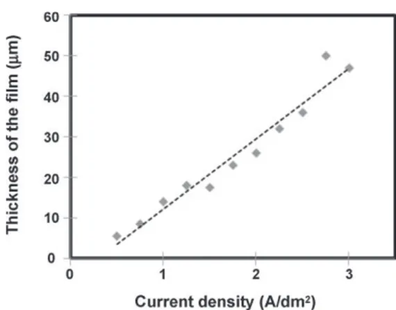
ana-Fig. 1. Thickness of the anodic film versus current density (t = 60 min, C = 150 g L−1,
T = 20◦C).
Fig. 2. Thickness of the anodic film versus time of anodizing (J = 1.2 A dm−2,
C = 150 g L−1, T = 20◦C).
lytical grade, and aqueous electrolyte solutions were obtained using deionised water.
2.1. Preparation process
The preparation of black anodic films including inorganic dyes followed the ESA Standard[10]for spacecraft. The process involved four main consecutive steps: surface pretreatments, anodizing, colouring and sealing.
The alloy sheet (40 mm × 20 mm × 3 mm) was degreased with ethanol and then etched in a mixed aqueous solution of Na2CO3(6.2 g L−1) and Na3PO4(12.5 g L−1) at
pH 11, for 5 min at 93◦C and neutralized in aqueous HNO
3(50%, v/v) for 3 min at
room temperature. The sheet was rinsed in distilled water at the end of each step. The sheet was then used as anode and a lead plate (3 mm × 40 mm × 40 mm) as counter-electrode in the electrochemical cell. The anodizing step was partic-ularly studied: operational conditions were, for a given duration (in the range
Fig. 3. Porosity of the film versus its thickness (controlled by varying the anodizing time; J = 1.25 A dm−2, C = 150 g L−1, T = 20◦C).
Fig. 4. Thickness of the anodic film versus anodizing time (from Faraday’s law, experimental, theoretical compact film TCF, theoretical compact film without dis-solution TCFWD).
Fig. 5. Thickness and porosity of the anodic film versus sulphuric acid concentration (T = 20◦C, J = 1.25 A dm−2, t = 60 min).
20–120 min, usually for 60 min) in the galvanostatic mode (0.5 < Ja< 3.0 A dm−2,
typ-ically 1.2 ± 0.1 A dm−2) using a sulphuric acid solution (50 < C < 250 g L−1, usually
150 g L−1) thermally regulated (5 < T < 35◦C, typically at 20◦C). The samples were
then immediately rinsed in distilled water.
The anodized part was coloured by immersion in two successive baths: first for 15 min in a solution of cobalt acetate (200 g L−1; pH 6.5) regulated at 43 ± 2◦C, and
then for 10 min in a bath of ammonium hydrosulphide (30 g L−1; pH 9.3) at room
temperature. The samples were rinsed in distilled water after each step to remove excess solution.
Fig. 6. Thickness and porosity of the anodic film versus the electrolyte temperature (C = 150 g L−1, J = 1.25 A dm−2, t = 60 min).
Fig. 7. Young’s modulus of non-coloured anodic films versus porosity (T from 5 to 25◦C, C = 150 g L−1, J = 1.25 A dm−2, t = 60 min).
The sealing step occurred for 25 min in a bath regulated at 98 ± 2◦C and made
up of nickel acetate (NiCH3COO·4H2O) and boric acid (both at 5 g L−1).
2.2. Microscopic and chemical analysis
The meso- and nanostructures of the coatings were observed by field-emission gun scanning electron microscopy (FEG-SEM) with a JEOL JSM6700F device. Thick-nesses were measured on the cross-sections of the samples and energy dispersive X-ray (EDX) spectroscopy analyses were performed to identify the chemical com-position inside the film, and especially the location of the dyes. Moreover, analyses by inductively coupled plasma (ICP) were performed to determine the Al, Zn and Cu ion contents in the electrolyte at the end of anodizing.
2.3. Porosity measurement
Porosity was measured before the colouring and sealing steps. The surface of the anodic films was observed using FEG-SEM and the resulting images were analysed with the free software ImageJ. The ratio between the pore areas and the total surface area analysed was taken to be the porosity of the anodic film, i.e. the porosity was considered homogeneous through the whole thickness of the anodic film.
2.4. Nanoindentation
The nanoindentation tests were performed on an XP apparatus (Agilent Tech-nology) to evaluate the Young’s modulus (E) of our anodic films. A Berkovich tip was used with a CSM (continuous stiffness measurement) modulus to obtain dynamic measurements on the surface of the films. The CSM frequency used was 45 Hz with a strain rate of 0.05 s−1. The maximum depth on indentation was 2000 nm, i.e. lower
than 10% of the total thickness (about 20 mm), in order to avoid substrate effects. With homogeneous films, an average value was determined for 20 measurements between the depths of 800 and 1000 nm.
2.5. Absorptivity and emissivity
Hemispheric absorptivity measurements were performed on an Elan 510 reflec-tometer. The light source used was a xenon lamp with wavelengths from 250 to 2500 nm and a spectral distribution comparable to that of sunlight (the main differ-ence is in the near infrared). Normal emissivity measurements were performed on an Elan 520 emissiometer operating at 70◦C.
3. Results and discussion 3.1. The anodizing step
3.1.1. Current density and time of anodizing
The growth of the anodic film occurs according to reaction(1)
and is mainly controlled with the current density and the anodizing time:
2Al + 3H2O → Al2O3+6H++6e− (1)
Figs. 1 and 2show the variations of film thickness as a function of the current density and the time of anodizing, respectively.
Fig. 8. EDX analysis of the cross-section of a film with an initial porosity of 40% (T = 20◦C, C = 150 g L−1, J = 1.25 A dm−2, t = 60 min). (a) After anodizing, (b) after
immersion in cobalt acetate (first colouring bath) and (c) after precipitation of dyes (second colouring bath).
The measured thickness increased with time and current den-sity, in agreement with Faraday’s law, while the porosity steadily increased with thickness (Fig. 3).
It is now possible to calculate the faradic rate at the anode[13]
taking into account both the experimental thickness and the alu-minium content in the anodizing electrolyte.Fig. 4 thus shows the virtual thickness of the compact film (TCF), after correcting the experimental porous film thickness by its porosity, as well as the TCF without acid dissolution (TCFWD), i.e. taking into account the amount of aluminium dissolved in the electrolyte. The corre-sponding anodic efficiency (i.e. TCFWD/faraday’s thickness ratio) in these experimental conditions is decreased from 74 to 58% in the 20–120 min time range, in agreement with previous works
Fig. 9. Simulation of the sulphide species distribution versus pH.
3.1.2. Concentration and temperature of the electrolyte
Fig. 5shows the influence of the concentration of sulphuric acid on the film thickness. In the 50–250 g L−1concentration range, the thickness of the anodic film remained constant, while there was an increase of the porosity (Fig. 5) for the same experimental condi-tions.
Both the thickness and porosity of the anodic films were also studied as a function of the electrolyte temperature (Fig. 6). The film thickness was constant (about 20 mm) for electrolyte temperatures between 5 and 27◦C, then drastically decreased between 27 and 30◦C reaching values lower than 6 mm at temperatures higher than 27◦C. There is a proportional increase of the porosity from 10 to 50% for electrolyte temperatures in the range 5–25◦C. At higher temperatures, the porosity became so high and irregular that the thickness significantly decreased.
The porosity of the anodic film mainly depends on the chemical dissolution (reaction(2)) occurring at its surface with the acidic electrolyte:
Al2O3+6H+→2Al3++3H2O (2)
So, the porosity changes are influenced by the bath parameters because chemical dissolution kinetics is mainly influenced by the temperature and the concentration of the electrolyte[15]. In con-trast, these parameters had a very low influence or no impact at all on the electrochemical reaction (reaction(1)) in this temperature range.
3.1.3. Mechanical characteristics
Nanoindentation measurements were performed on samples with different porosities (10–50%). The dynamic method of inden-tation firstly shows a homogeneous value of Young’s modulus of the anodic film through its whole thickness.Fig. 7reveals how Young’s modulus behaves with increasing porosity.
The relationship between Young’s modulus and porosity was previously described by Wang[16]using the following equation: E = E0exp(−(bp + cp2))
where p is the porosity, and b and c are constants.
Experimental points are well fitted for porosities up to 30% with the following parameters (E0= 86.2 GPa, b = 0.2, c = 2.48). Never-theless, at high porosities Young’s modulus collapses. Wang[16]
described such a phenomenon for high porosities even though they did not fit the theoretical relationship well. For a porosity of 50%, nanoindentation measurements were not exploitable but Young’s modulus was extrapolated and evaluated at about 20 GPa. 3.2. The colouring steps
Fig. 8shows the distribution of S, Co and Ni versus the depth inside the anodic film, its surface being located on the left of the curves while the film/substrate interface is on the right. Sulphur is already present in the anodic film (Fig. 8a), before the first colouring step (with cobalt acetate), due to the incorporation of sulphates from the sulphuric acid electrolyte during anodizing[17].
Impregnation by cobalt acetate (first step of colouring) causes the simultaneous alteration of the sulphur content from the film surface and cobalt incorporation through the whole film (Fig. 8b).
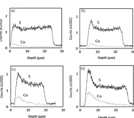
Fig. 10. EDX analysis of the cross-section of coloured anodic films (T from 5 to 20◦C, C = 150 g L−1, J = 1.25 A dm−2, t = 60 min) with an initial porosity of: (a) 10%, (b) 20%, (c)
The alteration of the sulphur content at the film/electrolyte inter-face could probably be explained by the higher temperature (T = 43 ± 2◦C) of the cobalt acetate electrolyte or by the integration of acetates in the film instead of sulphates. Moreover, because of the impregnation process, cobalt incorporation appears quite irreg-ular due to the diffusion and capillarity difficulties in the tortuous mesopores[11].
After the second colouring step, there was an increase of the sul-phur content through the whole film thickness, but especially near the surface (Fig. 8c). The presence of sulphur is due to its introduc-tion during the second colouring step, through impregnaintroduc-tion with ammonium sulphide and the precipitation of cobalt sulphide.
The reaction between cobalt acetate (pH 6.5) and ammonium sulphide (pH 9.6) results in CoS precipitation[18]according to: Co(CH3COO)2+(NH4)2S → CoS + 2CH3COONH4 (3) In the second colouring bath, i.e. at high pH (about 9.6), the sta-ble ionic species are Co(OH)2, CH3COO−(pKa= 4.8), NH3and NH4+ (pKa= 9.3) as well as HS−(Fig. 9). However, due to the low solubility product (Ks= 1.9 × 10⁻²⁷[19]) of solid CoS, precipitation could be considered as quantitative.
Anodic films with different initial porosities (10–40%) were coloured. EDX measurements were then performed on cross-sections to localize the dyes in the different films (Fig. 10a–d).
Sulphur is present throughout the coloured anodic films (before sealing), whatever the initial porosity. Moreover, both the amount of dye that finishes up in the pores and the depth of impregnation, increase with the initial porosity. These results stress that the
tor-Fig. 11. EDX analysis of the cross-section of a coloured sealed anodic film with an initial porosity of 40% (T = 20◦C, C = 150 g L−1, J = 1.25 A dm−2, t = 60 min).
tuosity of the mesopores restricts the impregnation of the cobalt acetate and ammonium sulphide and that deep dark colouring sometimes requires repeated dips[9].
3.3. The sealing step
The sealing step is usually considered as hydration of the anodic film, inducing a volume expansion of the film and hence pore
occlu-Fig. 12. SEM surface views of anodic films (T from 5 to 20◦C, C = 150 g L−1, J = 1.25 A dm−2, t = 60 min) after colouring and sealing with different initial porosities: (a) 10%, (b)
sion[20,21]. However, in this case, pore closing also results from the additional precipitation of nickel hydroxide, at the top of the coating, as shown on the EDX profiles (Fig. 11).
3.3.1. Surface observations
Fig. 12a–e shows SEM top views of anodic films prepared at dif-ferent anodizing temperatures, i.e. with difdif-ferent initial porosities and with subsequent colouring and sealing.
Anodic films, prepared at an anodizing temperature from 15◦C, i.e. with an initial porosity higher than 30%, show micro-cracks after colouring and sealing (Fig. 12c–e). From the crazing point of view, colouring and sealing are key steps because uncoloured and unsealed anodic films with an initial poros-ity of 40% exhibited a surface free of microcracks even after heat treatment (150◦C for 25 min) in agreement with previous works[22]. This crazing phenomenon could be explained by the coefficient of thermal expansion of coloured anodic films, which is nearly 10 times lower than that of the substrate[12]. Indeed, the sealing temperature is regulated at 98 ± 2◦C and results in tensile stresses occurring in the anodic film. Furthermore, it changes the residual stresses and affects the overall mechanical characteristics
[12,21].
3.3.2. Mechanical behaviour
Fig. 13presents the evolution of Young’s modulus as a function of the indentation depth and at different steps of the preparation process.
Young’s modulus appears constant (about 80 GPa), before the colouring and sealing steps. After colouring, the chemical changes occurring in the film, especially dye precipitation, reduced the modulus particularly near the surface, where CoS solids were specifically located. The loss of Young’s modulus can be directly due to the decreased sulphur content of the film during the impregna-tion in cobalt acetate. Sulphates from the films are indeed released into the bath, from near the film surface, which explains the presence of a gradient of modulus causing modifications of the mechanical characteristics. The modulus increased steadily along the film depth, until it reached the initial value (about 80 GPa) when the amount of dyes had become negligible. Film sealing led to an additional decrease of Young’s modulus; the decrease was greater when the sealing duration was longer (50 min. instead of 25 min.).
Fig. 13. Young modulus during indentations for four samples (T = 5◦C, C = 150 g L−1,
J = 1.25 A dm−2, t = 60 min) with initial porosities of 10% (after anodizing, after
colour-ing, after sealing 25 min, after sealing 50 min).
The Young’s modulus gradient also depends on porosity (Fig. 14a–d) and thus on the amount of dyes included in the films (Fig. 10).
In all cases, the modulus seems to tend to the initial value obtained after anodizing and before any post-treatment. More-over, the Young’s modulus gradient clearly depends not only on the porosity and microcracks but also on the chemical content of the film, i.e. dye location and amount, as well as the hydration level, especially resulting from the sealing step. Below, we study if these chemical or physical changes have or do not have an influence on the desired thermo-optical properties.
4. Thermo-optical properties
Black anodizing is used in the space industry to change the thermo-optical properties of surfaces, specifications recommend-ing a minimum absorptivity of 0.9 and emissivity of 0.93[10]. In the uncoloured anodic films (40% porosity) the absorptivity was evaluated to 0.35 and the emissivity to 0.89.
Fig. 15a and b shows the evolution of the normal emissivity and the solar hemispheric absorptivity of black anodic films as a function of their thickness. Two anodizing temperatures (5 and
Fig. 14. Young modulus of coloured and sealed samples (T from 5 to 20◦C, C = 150 g L−1, J = 1.25 A dm−2, t = 60 min) with different initial porosities: (a) 10%, (b) 20%, (c) 30%
Fig. 15. Normal emissivity (a) and solar hemispheric absorptivity (b) depending on the thickness of the coating and the anodizing temperature (5◦C or 20◦C).
20◦C) were used to evaluate the influence of the film characteristics (porosity and chemical content) on these two properties.
Emissivity and absorptivity were only affected for anodic film thicknesses lower than 6 mm, while they were found to be inde-pendent of the anodizing temperature (5 and 20◦C), i.e. the porosity (10 and 40%, respectively). These results mean that, apart from the microcracks, the thermo-optical properties are only governed by the presence of CoS dyes.
5. Conclusion
Black anodic films were prepared according to a four-step pro-cess, including pretreatments, anodizing, colouring and sealing. Their characteristics (thickness and porosity) were easily con-trolled with the anodizing parameters (time, current density, concentration and temperature of the electrolyte). The increase of
porosity with the temperature or concentration of the electrolyte has a particularly significant influence on the Young’s modulus of the film measured just after anodizing. Wang’s model gives a good fit for experimental points at low porosities, while a collapse occurs for porosities higher than 35%.
The colouring step consists in the insertion of CoS precipitates in the tortuous mesopores. The quantity of dyes increased with the porosity but the dyes were still mainly located near the film surface. Young’s modulus was directly affected by this colouring step probably because of the degradation of sulphates in the film. The decrease in Young modulus was amplified by the sealing step. Moreover, the increase in porosity may also have an impact on tensile strength and residual stresses, explaining the formation of crazing patterns. So, reducing the porosity may be a good way to avoid crazing while keeping satisfactory thermo-optical properties. Acknowledgement
The authors thank Peter Winterton for his helpful comments. References
[1] S. Wernick, R. Pinner, P.G. Sheasby, The Surface Treatment and Finishing of Aluminium and its Alloys, vol. 2, 5th ed., Finishing Pub. LTD & ASM Intert. Ed., Teddington, England, 1987, pp. 730–754.
[2] L. Arurault, L’Actualité Chimique 327–328 (2009) 45–50.
[3] L. Arurault, J. Salmi, R.S. Bes, Sol. Energy Mater. Sol. Cells 82 (3) (2004) 447–455. [4] H.H. Shih, Y.C. Huang, J. Mater. Process. Technol. 208 (1–3) (2008) 24–28. [5] M. Zemanova, M. Chovancova, P. Blaho, E. Usak, J. Valty, Trans. Inst. Met. Finish
86 (2) (2008) 109–114.
[6] M. Zemanova, M. Chovancova, Z. Galikova, P. Krivosík, Renew. Energy 33 (10) (2008) 2303–2310.
[7] L. Anicai, A. Pertache, T. Visan, Surf. Interface Anal. 40 (2008) 818–821. [8] T. Takenaka, H. Habazaki, H. Konno, Surf. Coat. Technol. 169–170 (2003)
155–159.
[9] A. Scherer, O.T. Inal, Thin solid Films 101 (1983) 311–328.
[10] ESA ECSS-Q-70-03A, Black-anodizing of metals with inorganic dyes, April 2006,
http://www.ecss.nl(update of the PSS-01-703).
[11] Y. Goueffon, L. Arurault, C. Mabru, C. Tonon, P. Guigue, J. Mater. Process. Technol. 209 (2009) 5145–5151.
[12] Y. Goueffon, C. Mabru, M. Labarrere, L. Arurault, C. Tonon, P. Guigue, Surf. Coat. Technol. 204 (2009) 1013–1017.
[13] L. Arurault, Trans. Inst. Met. Finish 86 (1) (2008) 51–54.
[14] S.J. Garcia-Vergara, P. Skeldon, G.E. Thompson, H. Habazaki, Electrochim. Acta 52 (2006) 681–687.
[15] M.D. Franke, W.R. Ernst, A.S. Myerson, AICHE J. 33 (2) (1987) 267–273. [16] J.C. Wang, J. Mater. Sci. 19 (1984) 801.
[17] G.E. Thompson, Thin Solid Films 297 (1–2) (1997) 192–201.
[18] A.K. Sharma, H. Bhojraj, V.K. Kaila, H. Narayanamurthy, Met. Finish 95 (12) (1997) 14–20.
[19] I.M. Kolthoff, J. Phys. Chem. 35 (9) (1931) 2711–2721. [20] T.P. Hoar, G.C. Wood, Electrochim. Acta 7 (3) (1962) 333–353.
[21] R.S. Alwitt, R.C. McClung, S. Jacobs, AIAA-922158-CP, AAIA Technical Papers (A92-31285 12-23), Washington, USA (1992) 39–45.