Any correspondence concerning this service should be sent to the repository administrator:
[email protected]
O
pen
A
rchive
T
oulouse
A
rchive
O
uverte (
OATAO
)
OATAO is an open access repository that collects the work of Toulouse researchers
and makes it freely available over the web where possible.
This is an author -deposited version published in:
http://oatao.univ-toulouse.fr/
Eprints ID: 3809
To link to this article: DOI:10.1016/j.surfcoat.2009.09.054
URL:
http://dx.doi.org/10.1016/j.surfcoat.2009.09.054
To cite this document
: Monceau, Daniel and Oquab, Djar and Estournes, Claude and
Boidot, Mathieu and Selezneff, Serge and Thebault, Yannick and Cadoret, Y. ( 2009)
Pt-modified Ni aluminides, MCrAlY-base multilayer coatings and TBC systems fabricated by
Spark Plasma Sintering for the protection of Ni-base superalloys. Surface and Coatings
Pt-modified Ni aluminides, MCrAlY-base multilayer coatings and TBC systems
fabricated by Spark Plasma Sintering for the protection of Ni-base superalloys
Daniel Monceau
a,⁎
, Djar Oquab
a, Claude Estournes
b,c, Mathieu Boidot
a, Serge Selezneff
a,
Yannick Thebault
a, Yannick Cadoret
da
Institut Carnot Cirimat; ENSIACET, 4, allée Emile Monso, BP-44362, 31432 Toulouse Cedex 4, France bCNRS; Institut Carnot CIRIMAT; F-31062 Toulouse, France
c
Plateforme Nationale de Frittage Flash du CNRS (PNF2); MHT, 118 route de Narbonne Université Paul-Sabatier, 31062 Toulouse Cedex 09, France dSNECMA, Materials and Process Division, SAFRAN Group, France
Keywords:
High temperature coatings Aluminide
MCrAlY
Spark Plasma Sintering Oxidation
Corrosion TBC
Pt-modified Ni aluminides and MCrAlY coatings (where M= Ni and/or Co) are widely used on turbine blades and vanes for protection against oxidation and corrosion and as bond coatings in thermal barrier coating (TBC) systems. The present work shows the ability of a new fabrication technique, the Spark Plasma Sintering, to develop rapidly new coating compositions and microstructures. This technique allows combining powders and metallic foils on a superalloy substrate in order to obtain multilayered coatings in a single short experiment. Fabrication of MCrAlY overlays with local Pt and/or Al enrichment is shown, as well as fabrication of coatings made of ζ-PtAl2, ε-PtAl, α-AlNiPt2, martensitic β - (Ni,Pt)Al or Pt-rich γ/γ′ phases.
The realization of a complete TBC system with a porous and adherent Yttria Stabilized Zirconia (YSZ) layer on a γ/γ′ low mass bond coating is also demonstrated. Difficulties of fabrication are reviewed and discussed, such as Y segregation, risks of carburization, local overheating, or difficulty to coat complex shape parts. Finally, some first results of cyclic oxidation are given.
1. Introduction
Spark Plasma Sintering (SPS) was developed based on the idea of using the plasma of an electric discharge machine for sintering metal and ceramics[1]. Powders which are difficult or impossible to sinter by other techniques, such as SiC or WC, have been densified by SPS without any additives. The reasons for this success are not clearly identified. It was thought initially that plasma is created between grains by the pulse current. But the electric current also causes the fast heating of powders in a graphite die by Joule effect. Specific effects of the spark plasma, including impact, could be involved but also the effect of the electric field, the electric current in a conductor or the skin current on a semiconductor and insulator, the rapid heating and cooling[2]. Also, it is important to note that sintering is performed in a vacuum chamber, with graphite die and punch which impose a very low oxygen partial pressure and that uniaxial load is applied by the graphite punch.
The possibility to coat structural alloys using SPS has never been reported in review papers on coating fabrication [3] nor in SPS reviews[2]. Only an extensive recent review by Orru et al.[4]report few works on ceramic coatings for structural metallic alloys. Indeed, questions arise about the possibility to industrialise such SPS coating process. Nevertheless, uncoated parts of complex shape as large as
500 mm, are currently in production. In addition, pseudo-isostatic pressure can be obtained by embedding the part to sinter in a not sintering powder [5–7]. Then, it is reasonable to think that SPS coatings could be produced in a close future as it has been demonstrated for Functionally Graded Materials (FGM) by Tokita
[8]. If so, this process has several advantages including no pollution by chemicals, no dangerous gases, minimum waste of materials, and a very fast processing.
Performance and fuel efficiency improvements of gas turbine rely upon a continuous increase in the operating temperatures. On single crystal Ni-base superalloy blades, multilayered coatings are devel-oped to respond to several types of attack. An ideal coating should be a thermal barrier reducing the operating temperature of the superalloy blade, it should be resistant to erosion and to CMAS corrosion, it should be also a diffusion barrier to prevent high temperature oxidation and hot corrosion of the superalloy, and finally it should not degrade the mechanical properties of the superalloy. Until now, state of the art coatings include environmental coatings made of overlay MCrAlY, where M is a combination of Co and Ni. High temperature oxidation of these overlay coatings can be improved by Al and/or Pt surface enrichment[3–9]. For pure oxidation conditions, Pt-modified Ni aluminides diffusion coatings perform very well. They are generally β-(Ni,Pt)Al single phased. But γ-Ni/γ′-Ni3Al Pt-rich
coatings can be used also. They result from a simple interdiffusion of an electrolytic Pt layer[10] or can be enriched in Al and reactive
Corresponding author.
element such as Hf by pack cementation[11]. In order to reduce the temperature of cooled blades and vanes, these coatings can be used as bond coatings under a thermal insulation layer made of Yttria Stabilized Zirconia (YSZ). In all cases, metallic coatings should form an α-alumina diffusion barrier (Thermally Grown Oxide — TGO) to protect the system against further oxidation. Reactive elements improve TGO adherence and reduce its growth kinetics. Cr content is necessary for resistance to hot corrosion[12].
Development of such multilayered coatings requires numerous fabrication techniques [3] and the cost, complexity and delay to obtained test coupons certainly slow down the research. Then, any shortcut in the development process should allow to test innovative solutions or to optimize existing compositions. Recently, it was demonstrated that a fully dense MCrAlY and Al–Pt surface modified NiCoCrAlYTa coating could be prepared in less than 1 h using the SPS process[13,14]. Some of these results will be completed below. It will be shown also that all kinds of Ni aluminide diffusion coatings can be obtained, including reactive elements doped with Pt-rich γ/γ′ bond coatings. Finally, the possibility to process a full TBC system in a one step process will be discussed and an example will be given with first results on thermal cycling resistance.
2. Experimental
The substrates used for this study were 8, 9 or 24,5 mm diameters discs prepared from single crystal first generation Ni-base superalloy AM1® or AM3® rod. Their compositions and description can be found in
[15]. Before use, the substrate surface was mechanically polished down to 0.25 µm diamond grit. NiCrAlY and NiCoCrAlYTa commercial powders (resp. AMDRY 962 and 997) were used for coatings, as well as pure Pt and Al foils with thickness between 2 and 10 μm. Yttria Stabilized Zirconia powder was used for the fabrication of TBC systems. The grain size was 50 to 200 nm (Tosoh Corporation, 10 mol%Y2O3).
All samples presented in this study were prepared by SPS (Dr Sinter 2080, SPS Syntex Inc., Japan). This SPS equipment, consists of a pulsed (3.3 ms of duration) direct current generator, a hydraulic press system, a vacuum and water cooled chamber, upper and lower punch electrode graphite spacers and finally control systems for the temperature (thermocouple or optical pyrometer), environment pressure inside the chamber and for the positioning of the lower electrode on z-axis which allows to follow the shrinkage of the sample. The materials were loaded onto 8, 15, 24.5 or 30 mm inner diameter cylindrical graphite dies. The pulse pattern 12-2 (i.e. 12 pulses followed by 2 rest intervals) recommended by the system manufacturer was used. The temperature was monitored by a thermocouple placed in a small hole located at the surface of the die. A heating rate of 100 °C/min was used to reach the final temperature 950 or 1000 °C. Dwell time at the desired temperature was between 0 and 30 min. Uniaxial loads of several kN (2.5 to 7.8) depending on the diameter of the die were applied for the first minute of the cycle to ensure a good electric contact of the spacers/punches/die.
In order to add RE in Ni aluminide coatings, some of the AM1 superalloy substrates were PVD coated before the SPS process. The substrates were ion-etched for a few seconds prior to deposition. Then radio-frequency-sputtering with a Leybold–Heraus sputtering ma-chine was performed. Several thicknesses of Hf, Si and Y layers were tested to obtain several levels of doping of the final coatings, i.e. 30– 240 nm for Hf, 20–320 nm for Si and 30–350 nm for Y. To limit oxidation of the thin films before SPS, the substrates were conditioned in an Ar atmosphere up until a few minutes before the SPS process. 3. Results and discussion
3.1. Fabrication of dense coatings using powders and/or metal foils
Concerning the fabrication of coatings by SPS for the protection of structural alloys against high temperature oxidation and corrosion,
only works on the protection of Nb[5]and Ni-base superalloys[13,14]
can be found in the literature to the authors' knowledge. Murakami et al.[5]have used SPS to coat a Nb substrate with Mo(Si,Al)2–Al2O3
composite and B-doped Mo5Si3layers. To fabricate the coating, they
used powders and inserted an Al foil between the powder and the Nb substrate. A partial oxidation of the Al layer was observed during the process in some cases and the reason for its formation remained unclear. Oquab et al.[13]have shown that it was possible to fabricate a fully dense NiCoCrAlYTa coating on a Ni-base superalloy substrate, using a commercial powder (AMDRY 997). They have shown that despite the uniaxial applied load, it was possible to fill a deep hole in the substrate without forming any pores. Surface modifications of the overlay NiCoCrAlYTa coating were obtained by adding 10 μm thick Al and/or Pt foil(s)[13,14]. This results in a β - NiAl phase or Pt-modified β phase at the coating surface over the regular γ/γ′/β inner coating. Even without Al added, Pt overcoating causes Al uphill diffusion[16]
from the NiCoCrAlYTa to form β[14]. Such a coating could combine good oxidation resistance (due to Pt-modified β) and corrosion protection (due to the Pt and Cr-rich MCrAlY) in case of surface failure. Nevertheless, it was shown that a Pt and Y-rich phase was formed at β grain boundaries during the process and that this resulted in grain boundary oxidation after 500 h at 1100 °C isothermal oxidation in air[14]. It is noticeable that the layering of foils made of different pure metals does not lead to Kirkendall voids, certainly due to the applied stress during sintering in a reducing atmosphere.
Aluminide coatings can be fabricated by the exothermic reaction between Pt and Al layers[17]. In this present work, layering of Pt and/ or Al foils was also used to obtain Pt-rich Ni aluminides diffusion coatings using the SPS process (Table 1), here again, no Kirkendall voids were observed. Using a combination of powders and foils, the process is versatile and allows to produce a large variety of compositions and microstructures of protection coatings. The diffi-culties occurring during this process are now reviewed.
3.2. The question of the processing temperature
Temperature is generally not well known in the SPS process. Optical pyrometer or thermocouple at the surface of graphite die is used to measure the graphite surface temperature (Fig. 1). But heterogeneity of temperature can be expected because of several reasons: 1/fast heating and cooling, 2/local interfacial electrical resistance between grains and then local overheating by Joule effect, 3/possible spark or plasma effect, 4/local overheating when producing highly exothermic reactions such as between pure Pt, Al and Ni to form intermetallics. For the coatings fabricated in this study, a good reproducibility of the results was obtained after calibration using two
Table 1
List of sample types fabricated by SPS processing. Architecture NiCrAlY NiCoCrAlYTa AM3/ NiCoCrAlYTa AM3/NiCoCrAlYTa/ Al AM3/Al/ NiCoCrAlYTa AM3/ NiCoCrAlYTa/Pt AM3/NiCoCrAlYTa/NiCoCrAlYTa/Al/Pt AM3/NiCoCrAlYTa/Pt/NiCoCrAlYTa AM1/Pt AM1/Al/Pt AM1/Pt/Al AM1/Pt/Al/Pt/Al… AM1/RE/Pt AM1/RE/Al/Pt AM1/RE/Pt/ZrO2–Y2O3
AM3 and AM1: superalloy substrates; NiCrAlY and NiCoCrAlYTa: AMDRY 962 and 997 powders; Al and Pt: metallic foils (between 2 and 10 μm); RE: combination of Si, Hf and Y RF-PVD deposits.
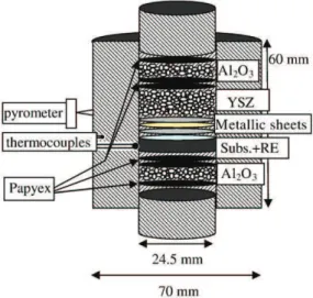
K-type thermocouples at the die surface (in a 3 mm deep hole) and inside the die close to the sample. Alumina powder was also used on both sides of the assembly (Fig. 1) in order to have an electric insulation and to heat the sample mainly by the graphite die.
3.3. Carburization during SPS process
Yu et al.[18]have shown that SPS could be used to restore an Air Plasma Sprayed WC–Co coating on a steel substrate. Carbon diffused from the graphite punch or die was used to restore the WC phase from W2C, and the coating was densified at 800 °C. In[13]it was shown
that a deep carburization results from the sintering of NiCoCrAlYTa powder. Cr3C2and TaC were identified by XRD. It was found for a
650 μm thick NiCoCrAlYTa SPS coating (Fig. 2) that the carburized layer thickness is about 142 μm after SPS (heating to 1000 °C over 10 min and immediate cooling down). When annealing in air at 1100 °C, the carburization front progressed: 276 μm after 24 h, 511 μm after 192 h and 537 μm after 500 h, i.e. the process follows parabolic kinetics (z2= k·t + z°) with a rate constant k = 2E−11 m2/s (1100 °C) up to 192 h which slows down after that when the entire coating is carburized. It is clear that the carburizing rate during the SPS (142 μm in the 10 min heating to 1000 °C) is much faster than can
be expected from C diffusion in sintered NiCoCrAlYTa. This means that C diffusion at the surface of the NiCoCrAlYTa grains before sintering, or transport of CO in the SPS chamber is involved.
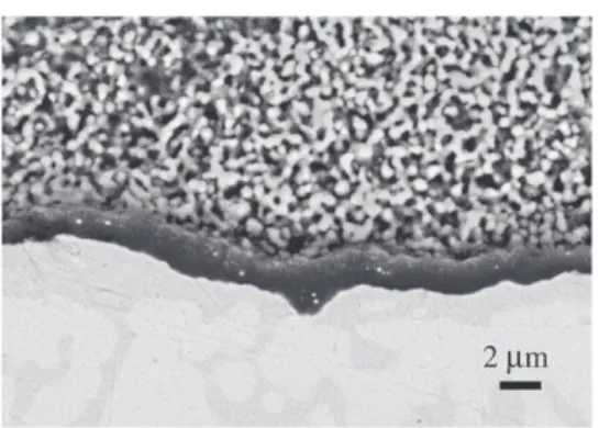
Carbide formation (WC) was also observed in the Ni-base AM1 superalloy during SPS. A carburized zone of 234 μm is observed (Fig. 3c) after 1 min SPS at 950 °C followed by 10 min annealing in air at 1100 °C.
3.4. Consequences of carburization
The most visible consequence of C ingress in MCrAlY or superalloy during SPS process is the formation of carbides (Figs. 2, 3b, c). Carbides are believed to be detrimental to high temperature oxidation and thermal cycling resistance. Indeed, their formation removes Cr from the matrix and the presence of this ceramic second phase may cause stresses during cycling. They can also oxidize at the sample surface and disturb the formation of the protective alumina layer. A second consequence of carburization was observed in this study with the fracture of the aluminide coating. When a β-NiAl coating was formed by adding an Al foil and a smaller Pt foil over an AM1 super-alloy, and after an annealing in air at 1100 °C during 16.5 h, cracks were observed in β phase and at the β/γ′ interface after cooling (Fig. 4a). When another part of the sample was cycled 50 × 1 h at 1100 °C in air, opened cracks were observed at the initial location of β and β/γ′ interface (Fig. 4b) (note that β transforms to γ′ during cycling). This was observed only in the coating area close to the border of the Pt foil, so that no protection against carburization was achieved. In the center of the sample, where the coating was protecting against carburization by the 10 μm thick Pt foil, no crack was observed. No crack was observed neither in the many following experiments in which the Pt foil was as large as the superalloy substrate.
3.5. Solutions to prevent carburization
Carburization during SPS was observed in NiCrAlY, NiCoCrAlYTa and AM1 superalloy. In the same materials, it was observed that a 10 μm thick Al foil reduces slightly the kinetics of carburization but did not prevent it[13]. But for NiCoCrAlYTa coating on AM3 and Ni aluminide coatings on AM1, it was found that a Pt foil prevents carbide formation and carbon embrittlement of Ni aluminides. This was observed for a 10 μm Pt foil on NiCoCrAlYTa[14]. With Pt foils on AM1 sintered during 20 min at 1050 °C, a 6 μm thick foil (or thicker) of Pt is necessary to prevent carbide formation in AM1. If a Pt foil is combined with an Al foil, the same effect is obtained.Fig. 3b shows an AM1 sample which was covered on its entire surface by an Al foil, and covered partially by a Pt foil. The SEM cross section shows the carbides formation in AM1 where the superalloy was covered by Al only, and no carbide formation where AM1 was covered by Al and Pt.
A second solution was found to prevent carbide formation. Before introduction in the SPS equipment, AM1 samples are pre-oxidized 1 h in air at 1100 °C. This results in the formation of an oxide scale about 1 μm thick with an outer mixed oxide layer and an inner α-alumina scale which is continuous and protective. This solution is used to protect all the superalloy surfaces which are not to be coated.
A third solution to prevent carburization consists in adding YSZ powder on top of the foils used to coat the superalloy. A ceramic powder layer of 100 μm prevents any carbide formation in the bond coating. Obviously, this is very useful when preparing full TBC systems in the SPS. Up until now, it is not known if the ceramic top coat is a C diffusion barrier by itself, or if the TGO formed at the bond coating surface during the process is the diffusion barrier.
Finally, a fourth solution consists in spraying hex-BN powder onto the surface of the assembly. This technique was successfully tested with our materials.
Fig. 1. Schematic arrangement of materials in the graphite die for SPS processing (Subs. = superalloy substrate, RE = Y, Si and/or Hf deposit).
Fig. 2. Progress of the carburization front in SPS–NiCoCrAlYTa coating during 24 to 500 h annealing at 1100 °C in laboratory air.
3.6. Y segregation during processing
Kwakernaak et al. [19] have shown that the Y solubility in a NiCoCrAlY alloy with typical microstructure and composition, is very small. Then, Y dopant is mainly present in Ni5Y phase [20]. Y
segregates in 10 μm long Ni5Y in Ni20Co19Cr24Al0.2Y with large
grains of about 50 μm, whereas a fine dispersion of Ni5Y (1–2 μm) is
observed in a fine grain NiCoCrAlY of same composition. Toscano et al.
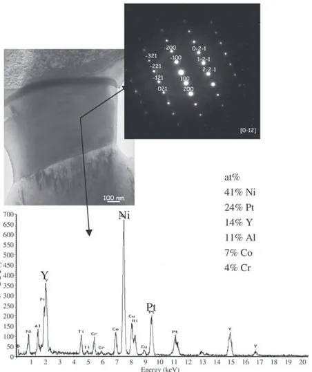
[21]have shown that Ni–Y compounds appear in NiCoCrAlY contain-ing 0.2–0.3at% Y after annealcontain-ing at 1000 °C, whereas, they were not present after annealing at 1100 °C, because Y solubility in γ and β phases certainly decreases with decreasing temperature. After SPS at 950 °C, it was expected then to see Y segregation at β/γ phase boundaries. This was observed in[13]with Y-rich phase surrounding the β phase at the interface with γ. Later, this Y segregation was also observed in Pt–Al-modified NiCoCrAlYTa[14](Fig. 5). TEM analysis identified this phase as being (Ni,Pt)5Y with as much as 14 at% Y
(Fig. 6). In this case, it is found that most of the Y is located in these precipitates and this confirms the work of Kwakernaak et al., but for a Pt-rich (Ni,Pt)5Y phase.
3.7. Preparation of aluminides coatings with defined microstructure and composition
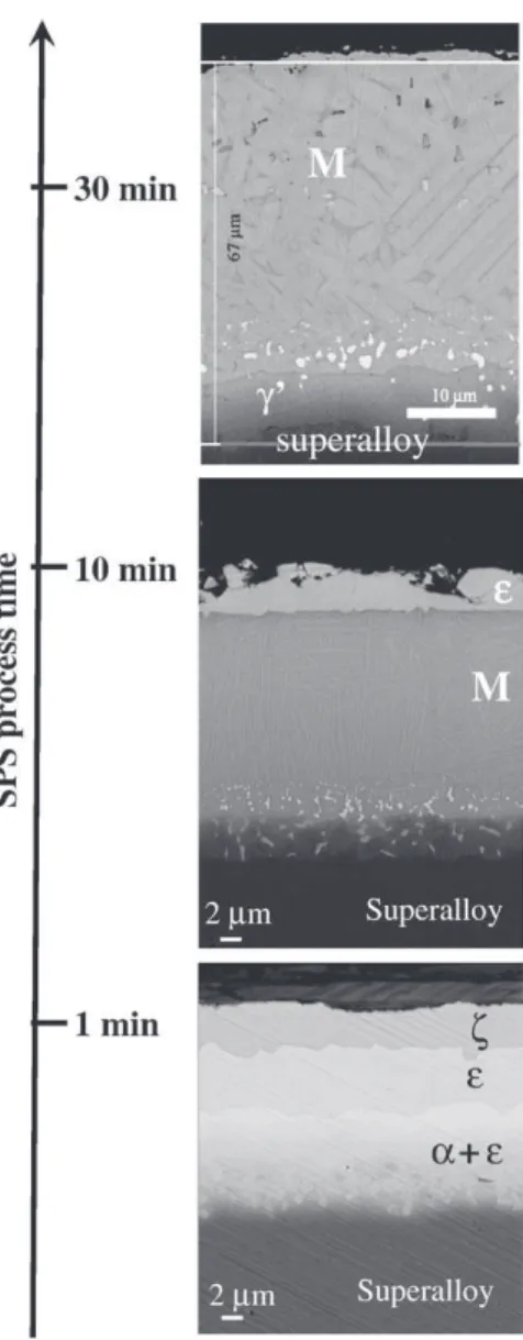
By using different thickness of Pt and Al foils, different dwell times during the SPS process and different durations of thermal treatment post SPS treatment, it was possible to fabricate coatings with ζ-PtAl2,
ε-PtAl, α-AlNiPt2, martensitic β, β, γ′, and γ/γ′ phases (Figs. 7–8). One
objective of this study was to fabricate an Al and Pt rich γ/γ′ coating on AM1 superalloy, able to form a pure alumina scale[16]. To obtain a composition with about 20 at% Al and 15 at% Pt, it was found that two diffusion paths are possible (Fig. 9). They both start with the formation of an external ζ-PtAl2(Fig. 7) layer to ε-PtAl. Then, one
path goes to β-(Ni,Pt)Al, to martensite β, to γ′ and to Pt-rich γ/γ′. The other path goes through α-AlNiPt2(Fig. 7) instead of β-(Ni,Pt)Al. This
shows that an α-AlNiPt2phase coating[22]can be seen as a precursor
of a Pt-rich γ/γ′ coating.
Fig. 3. Prevention of carbide formation a/ 1 h oxidation in air at 1100 °C of AM1 alloy prevents carbide formation during 3 min SPS at 950 °C; b/ Pt and Al foils on top of AM1 alloy prevent carbide formation (right side) whereas Al foil only does not prevent it (left side) after 30 min SPS at 950 °C; c/ carbide formation in AM1 alloy after 1 min SPS at 950 °C and 10 min annealing in air at 1100 °C.
Fig. 4. Cracks at β-NiAl grain boundaries when using insufficient protection against carburization (see text) for AM1 alloy/10 µm Pt/12 µm Al after 1 min SPS at 950 °C a/ and 16.5 h annealing at 1100 °C and cooling, b/ same sample after 50 cycles of 1 h at 1100 °C in air.
Fig. 5. Cross section of SPS sintered Pt–Al–NiCoCrAlYTa (SEM-BSE). “White” phase at NiCoCrAlYTa grain boundaries is enriched in Pt and Y.
3.8. Doping coatings in reactive elements
Reactive element (RE) doping was obtained by using a Y-alloyed powder for the MCrAlY-base coatings. For diffusion Ni aluminide coatings, Hf, Si and Y additions were obtained by PVD on the bare AM1 superalloy substrate before the SPS process. This process allowed preparation of doped coatings with various combinations of RE concentrations (Table 1,Fig. 10). Only few Hf or Y oxides could be found in the coating after SPS or annealing. Most of the RE were not oxidized and no void was created (Figs. 10–12).
3.9. One step fabrication of a complete TBC system
The fabrication of a complete TBC system was performed for the first time in one step by the SPS process (except for the preliminary PVD of reactive elements when used). Such an exercise is not obvious. Indeed, the Pt and Al metals and the YSZ have usually very different sintering temperatures. It was then necessary to optimize the sintering conditions of temperature, time and mechanical load. It was also necessary to use YSZ powder with small grains (50–200 nm) to give rise to enhanced sintering. The second difficulty concerns the bond coating/top coat interface adhesion. It requires the formation of an interfacial oxide (TGO), preferentially a pure alumina layer which provides the best diffusion barrier in service. But, the SPS chamber atmosphere is highly reducing as explained before. SPS conditions were found which allow the formation of the TGO during the one step
TBC fabrication. This alumina layer formation is certainly obtained by oxygen transfer from zirconia to the more stable alumina. Indeed, no alumina is formed in the absence of zirconia powder and it was shown previously that YSZ can be partially reduced during SPS sintering[23].
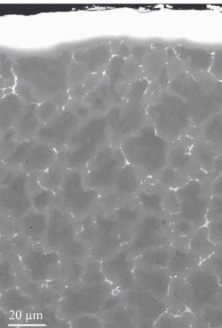
Fig. 11shows an example of TBC just after the SPS one step process. This system is composed of a thin Pt-rich γ/γ′ bond coating. The TGO is composed of pure alumina with some small zirconia inclusions. The TGO mean thickness is about 200 nm, as revealed by TEM analysis. Electronic diffraction has also shown that alumina was amorphous in the present case, just after SPS processing. The top coat is adherent onto the TGO. The YSZ that is formed is porous, nano-sized and not cracked, even after cross sectioning of sample.
3.10. First results of SPS coatings high temperature oxidation
Oquab et al.[14]reported preliminary isothermal oxidation results of Pt and Al-modified NiCoCrAlYTa SPS coatings at 1100 °C in air for durations up to 500 h. They found that this coating was an excellent α-alumina former with a low parabolic constant kp= 2E−8 mg2/cm4/s
between 192 h and 500 h. Nevertheless, because of the high Y content in the NiCoCrAlYTa powder (0.6 wt%) and Y segregation in the form of (Ni,Pt)5Y at the grain boundaries of the β - (Ni,Pt)Al, meant Y oxides
were formed in the oxide scale and also as intergranular oxidation. This is expected to result in low thermo-mechanical behaviour.
Concerning the SPS Ni aluminide coatings and full SPS TBC systems, first tests of cyclic oxidation were performed. The thermal
cycles consist in fast heating by moving samples into the hot furnace, 1 h at high temperature (including heating), and fast cooling during 15 min under a high flow of clean air.Fig. 12shows an example of a SPS processed TBC system after thermal cycling. This γ/γ′ based system is doped with Hf and Si. The TGO is composed of alumina with white precipitates of Hf-rich oxides. No internal oxidation is observed in this case, as has been observed for samples with higher dopant concentrations. First tests were performed at 1100 °C up to 300 cycles only. For some of the tested compositions, the SPS TBC system is still fully adherent, except at sample edges, as can be seen onFig. 13. Oxidation kinetics were evaluated from TGO thickness measurements on SEM cross sections. For example, a low mass γ/γ′ bondcoat fabricated with a single 2 μm thick Pt foil and a 60 nm Hf deposit shows a kp= 3E−7 mg²/cm4/s after 300 h. This value is closed to the
one found for α -alumina formation on β-NiPtAl-base TBC system without reactive elements [24] but slightly high for a Hf-doped alumina former. This can be related to the fact that the TGO formed on this bond coating composition is expected to form an external spinel layer on the top of the alumina scale[25]. Detailed high temperature oxidation results will be presented in a future paper.
3.11. Remaining questions and future developments
High quality oxidation protective coatings have been produced in a one step process using the SPS technique. This work follows the
Fig. 8. Microstructure of the aluminide coatings after SPS processing of AM1/10 µm Pt/ 12 µm Al during 1 min at 950 °C and increasing duration of post annealing in air at 1100 °C (SEM-BSE of cross sections).
Fig. 9. Ni–Pt–Al phase diagram showing 2 different diffusion paths from ζ-PtAl2phase to the Pt and Al-rich γ/γ′ final coating microstructure (Ni, Co and Cr are summed together, and Ti is summed with Al).
Fig. 7. Microstructure of the aluminide coatings after SPS processing of AM1/10 µm Pt/ 12 µm Al for different durations at 950 °C (SEM-BSE cross sections).
preceding works on surface modifications of alloys by Spark Plasma Sintering [5,26]. Nevertheless, some questions remained unsolved and should be addressed in future studies. Among them, it is still not clear if the microstructure evolution during the SPS process is controlled only by time and temperature or if kinetics and transformations are influenced by specific effect(s) of the pulsed high electric current passing through the die/punch/sample assembly. Thus, comparisons with annealing in a regular furnace should be performed. Concerning the fabrication of a TBC system in a one step process, the RE doping through PVD should be replaced by RE-alloyed metallic foils or powder in the SPS assembly or by using RE-doped superalloys. The formation of the initial TGO may be also improved with a thermal treatment allowing TGO full transformation to α-alumina. The SPS process could be used also to build even more complex multilayered structure, including a diffusion barrier at the bondcoat/superalloy interface, in order to limit Al diffusion toward the superalloy, and multilayered ceramic top coat to improve resistance to erosion.
4. Conclusions
To date, only few published works are available on SPS coatings. In these studies, SPS is used as a powerful tool to test rapidly a set of new compositions or microstructures. In the present work, it is shown that:
1. SPS is a powerful tool to fabricate a large range of coatings with defined compositions or to built complex multilayered architectures; 2. this can be done by combining powders and metal foils; 3. foils or substrates can be previously coated with thin films by PVD
in order to add controlled quantities of reactive elements; 4. carbide formation occurs because the SPS chamber atmosphere is
carburizing for metals such as Cr, Ta, W and reducing for oxides preventing the formation of a diffusion barrier;
5. carbide formation leads to cracks of β-NiAl containing coating upon cooling and thermal cycling at 1100 °C;
6. carbides do not form when the superalloy substrate is pre-oxidized for 1 h in air at 1100 °C to form an α-alumina protective inner layer, or when the top layer of the coating is YSZ, or a Pt foil, or if the surface is sprayed with hex-BN powder before sintering; 7. Pt- and/or Al-modified MCrAlY coatings were fabricated, with a slow growing alumina scale after 500 h at 1100 °C, but Y and Pt segregation occurred forming (Ni,Pt)5Y phase, which leads to
intergranular oxidation and certainly degrades the coating mechanical properties, i.e. Y concentration of 0.6 wt% is too high in such a coating;
8. Pt-rich γ/γ′ bond coatings can be obtained by combining Pt and Al foils. Two diffusion paths were identified from ζ-PtAl2to the desired
γ/γ′ microstructure: ζ-PtAl2- N ε-PtAl-N α-AlNiPt2- NPt-rich γ/γ′
and ζ-PtAl2- N ε-PtAl-N β-(Ni,Pt)Al-N Martensite-N Pt-rich γ/γ′;
Fig. 10. Pt-rich γ/γ′ SPS coating doped with Hf and Si (AM1 superalloy with 60 nm Hf and 320 nm Si PVD deposits/2 µm Pt). SEM-BSE cross section with corresponding EDX concentration profiles (average concentrations in windows as shown on cross section).
Fig. 11. One step SPS fabricated TBC system including AM1 substrate, Pt-rich γ/γ′ bond coating, alumina TGO and YSZ top coat (SPS of AM1/2 µm Pt/YSZ powder). SEM of cross section with TEM analysis of the TGO/bond coating interface.
Fig. 12. Cross section (SEM) of a one step processed SPS TBC system after 120 (+/−40) 1 h cycles at 1100 °C in air, showing adherent and porous YSZ top coat over alumina TGO containing Hf oxide precipitates (SPS of AM1/60 nm Hf-320 nm Si/2 µm Pt/YSZ powder).
Fig. 13. One step processed SPS TBC system after 300 cycles of 1 h at 1100 °C, showing adherent YSZ top coat (low mass Pt-rich γ/γ′ bond coat) with local edge spallation.
9. the obtained coatings are fully dense, and they present a very smooth interface with the substrate (smoother than VPS or pack cementation coatings);
10. a full TBC multilayer system can be built in a one step process, including the YSZ ceramic top coat, the interfacial alumina TGO and the Ni aluminide bond coating;
11. a multilayered ceramic top coats could be fabricated as well as a diffusion barrier at the bond coat/superalloy interface, using the same one step process, although this has not been demonstrated for the moment;
12. due to the specificity of SPS process, nanopowders or nanocrystal-line metal foils should allow to develop nanocrystalnanocrystal-line coatings. Acknowledgements
Part of this work was performed thanks to the financial support of DGA and SNECMA. AM3 alloy and AMDRY powders were furnished by Turboméca-SAFRAN company. TEM work was performed by M. C. Lafont at CIRIMAT laboratory. RF-sputtering was done at ICMCB, Bordeaux, France.
References
[1] K. Inoue, US Patent No. 3 250 892 (1966). [2] M. Omori, MSE A 287 (2000) 183. [3] J.R. Nicholls, MRS Bull. (Sept. 2003) 659.
[4] R. Orru, R. Licheri, A.M. Locci, A. Cincotti, G. Cao, MSER 63 (2009) 127. [5] T. Murakami, S. Sasaki, K. Ito, H. Inui, M. Yamaguchi, Intermetallics 12 (2004) 749. [6] Z. Song, S. Kishimoto, N. Shinya, Adv. Eng. Mater. 6 (2004) 211.
[7] N. Miyanoa, K. Tagaya, K. Kawase, K. Ameyamac, S. Sugiyama, Sensors and Actuators A (2003) 108.
[8] M. Tokita, Mat. Sc. Forum. 492–493 (2005) 711.
[9] T.A. Taylor, D.F. Bettridge, Surf. Coat. Technol. 86–87 (1996) 9. [10] D.S. Rickerby, US patent 005667663A (1997).
[11] B. Gleeson, B. Li, D. Sordelet, W.J. Brindley, International patent WO2006/076130, 2006.
[12] N. Birks, G.H. Meier, F.S. Pettit, Introduction to the High-Temperature Oxid. of Met, Cambridge University Press, 2006, p. 338.
[13] D. Oquab, C. Estournes, D. Monceau, Adv. Eng. Mat. 9 (5) (2007) 413. [14] D. Oquab, D. Monceau, Y. Thébault, C. Estournes, Mat. Sci. Forum. 595–598 (2008) 143. [15] P. Caron, T. Khan, Aerosp. Sci. Technol. 3 (1999) 513.
[16] B. Gleeson, W. Wang, S. Hayashi, D. Sordelet, Mat. Sci. Forum 461–464 (2004) 213. [17] B.S. Ramond, M. Carlin, M. Silva, J.R. Nicholls, Mat. Sci. Forum 461–462 (2004) 265. [18] L.G. Yu, K.A. Khora, H. Li, K.C. Pay, T.H. Yip, P. Cheang, Surf. Coat. Technol. 182 (2004)
308.
[19] C. Kwakernaak, T.J. Nijdam, W.G. Sloof, Metall. Mater. Trans., A 37 (2006) 695. [20] T.J. Nijdam, W.G. Sloof, Oxid. Met. 69 (2008) 1.
[21] J. Toscano, A. Gil, T. Hüttel, E. Wessel, D. Naumenko, L. Singheiser, W.J. Quadakkers, Surf. Coat. Technol. 202 (4–7) (2007) 603.
[22] B.S. Ramond, M. Silva, J.R. Nicholls, M. Carlin, EU Patent 20040292489 20041020, French patent 20030012619 20031028, US Patent Application 20050132717 (2003). [23] U. Anselmi-Tamburini, J.E. Garay, Z.A. Munira, A. Tacca, F. Maglia, G. Chiodelli, G.
Spinolo, J. Mater. Res. 19 (11) (2004) 3263.
[24] A. Vande-Put, D. Monceau, D. Oquab, Surf. Coat. Technol. 202 (2007) 665. [25] N. Mu, T. Izumi, L. Zhang, B. Gleeson, Mat. Sci. Forum 595–598 (2008) 239. [26] X.J. Chen, L.G.Yu, K.A. Khor, G. Sundararajan, Surf. Coat. Technol. 202 (13) (2008)