HAL Id: tel-01865813
https://tel.archives-ouvertes.fr/tel-01865813
Submitted on 2 Sep 2018HAL is a multi-disciplinary open access archive for the deposit and dissemination of sci-entific research documents, whether they are pub-lished or not. The documents may come from teaching and research institutions in France or abroad, or from public or private research centers.
L’archive ouverte pluridisciplinaire HAL, est destinée au dépôt et à la diffusion de documents scientifiques de niveau recherche, publiés ou non, émanant des établissements d’enseignement et de recherche français ou étrangers, des laboratoires publics ou privés.
Synthesis of Metal and Conjugated Polymer
Nanostructures in Hexagonal Mesophases for
Application in Fuel Cells and photocatalysis
Dita Floresyona
To cite this version:
Dita Floresyona. Synthesis of Metal and Conjugated Polymer Nanostructures in Hexagonal Mesophases for Application in Fuel Cells and photocatalysis. Polymers. Université Paris Saclay (COmUE), 2017. English. �NNT : 2017SACLS206�. �tel-01865813�
1
NNT : 2017SACLS206
THESE DE DOCTORAT
DE L’UNIVERSITE PARIS-SACLAY
PREPAREE AU
« L’UNIVERSITE PARIS-SUD»
ECOLE DOCTORALE N° 571
Science Chimiques : Molécules, Matériaux, Instrumentation et Biosystèmes
Spécialité de doctorat : chimie
Par
Dita Floresyona
Synthèse de nanostructures métalliques et de polymères conducteurs dans des mésophases hexagonales pour des applications dans les piles à combustible et le traitement de l'eau
Thèse présentée et soutenue à Orsay, le 15 Septembre 2017 :
Composition du Jury :
M. Ally AukaulooMme. Sophie Cassaignon M. Boniface Kokoh Mme. Anne-Lucie Teillout Mme. Hynd Remita Mme. Laurence Ramos
Professeur des Universités (Univ. Paris-Sud)
Professeur des Universités (Université Pierre et Marie Curie)
Professeur des Universités (Université de Poitiers) Maitre de Conférence (Univ. Paris-Sud)
Directrice de Recherche CNRS (Univ. Paris-Sud) Directrice de Recherche CNRS (Université de Montpellier) Présidente du jury Rapporteur Rapporteur Examinatrice Directrice de thèse Co-directrice de thèse
ii
Acknowledgements
I want to express my sincere gratitude to my supervisor, Dr. Hynd REMITA. I am grateful because she has been willing to accept me as her PhD student. I thank her for all the knowledge, guidance, and patience during my thesis. Her passion for research, her dynamic in working, her friendliness, and her awareness to people, inspired me. She taught me to be tough. She has given me opportunities to attend many conferences, to participate in scientific events, and to have many collaborations.
I want to thank my co-supervisor, Dr. Laurence RAMOS for the discussions, input, and detail corrections of my work and my thesis. She has been really patience in explaining all the detail calculations in SAXS and WAXS measurement. I thank her for her fast response.
I would like to thank Prof. Boniface Kokoh, Prof. Sophie Cassaignon, Prof. Ally Aukauloo, and Dr. Anne-Lucie Teillout. I am glad that they accepted to be a member of juries of my thesis.
I would like to thank Dr. Anne-Lucie Teillout and Prof. Pedro de Oliveira (LCP, Université Paris-Sud) for their guidance and help during electrochemistry experiment, for the fruitful discussions, and for correcting the electrochemistry part of my thesis. I particularly thank Anne-Lucie for her patience and help..
I thank Philippe Dieudonne-George for SAXS and WAXS experiments in Laboratoire de Charles Coulomb in Université de Montpellier.
I would like to thank all my collaborators. I thank Prof. Fabrice Goubard and Prof. Pierre-Henri Aubert (Université de Cergy-Pontoise) for the electrochemistry and conductivity measurements, for the discussion, and input for my work. I thank Prof Teko Napporn (Université de Poitiers) for glucose oxidation experiments, discussions, and very useful input for my thesis. I thank Prof. Isabelle Lampre (LCP, Université Paris Sud) for Fluorescence Spectroscopy experiments. I thank Jérémie Mathurin and Prof. Alexandre Dazzi from (LCP, Université Paris Sud) for AFMIR experiments. I thank Dr. Jean-louis Marignier for the experiments in ELYSE. I thank Dr. Daniel Bahena (IPCYT, Mexico) for HAADF-STEM and EDS analysis. I thank Diana Dragoe (ICCMO, Université Paris
iii Sud) for XPS analysis, data treatment, and discussion. I thank Patricia Beaunier (UPMC) for TEM characterizations.
I warmly thank Stephanie Mendes Merinho and Ally Aukauloo (ICCMO, Université Paris Sud) for O2 evolution experiments and for fruitful discussions.
I thank Mireille Benoît for being very helpful in finding chemical products, set-up some experiments, and dealing with many technical problems in the lab.
Special thanks to my friends and colleagues in LCP. I thank Srabanti Ghosh for the guidance and supervision during my master internship, it helped me a lot to understand my PhD projects. I thank Iyad SARHID, for helping me to prepare all the documents for Ecole Doctorale in 2 hours before the deadline, so I could finally be accepted. I thank Maria Guadalupe, Xiaojiao Yuan, Anais Lehoux, Marie Clement, Ana Laura, Teseer Bahri, and Zhengpeng Chui for helping me not only with the experiments and data treatment, but also to deal with French administration. I thank them for the good working ambience, friendship, and humor. They make my Monday mornings and comeback after vacations not so difficult.
I want to thank my Indonesian friends, for Mbak Arum, Mba Alvi, Ajeng, mbak Sundari, Tesa, Risa, Uun, and Vini. I thank them for the “ngopi-ngopi cantik” and “jalan-jalan bego” times in Paris during the weekend.
And at last but most importantly, I want to thank my family, especially my parents, for the endless love, support, and prayers. They are the two people who always believe in me, in my capability, who never stop me to continue education and pursue my dreams. This thesis is dedicated to them.
iv
Table of Content
Adknowledgements Table of content General introduction Résumé généralCHAPTER I. Objectives and State of the Arts I.1 Global environmental problem
I.2 Synthesis of nanomaterials
I.2.1 Radiolysis technique for the synthesis of nanomaterials I.2.2 Principle of radiolysis
I.2.3 Dose rate effect
I.2.4 Synthesis of nanomaterials using templates I.3 Soft templates: Swollen hexagonal mesophases
I.3.1 Surfactant
a. Anionic surfactants b. Nonionic surfactants c. Cationic surfactants
d. Zwitterionic (amphoteric) surfactants I.3.2 Surfactant self-assembly
I.3.3 Critical packing parameter (CPP) I.3.4 Self-assembly in hexagonal mesophases
I.3.5 Characterization of hexagonal mesophases by Small Angle X-Ray Scattering (SAXS)
I.3.6 Swollen hexagonal mesophases
I.4 Synthesis of nanomaterials in hexagonal mesophases
I.4.1 Synthesis of porous metal nanostructures in the water phase of hexagonal mesophases
a. The role of surfactants b. The role of the dose rate
I.4.2 Synthesis of conjugated polymer nanostructures in the oil phase of hexagonal mesophases
CHAPTER II. Experimental Part
II.1 Preparation of hexagonal mesophases
II.1.1 Synthesis of metal nanostructures in the aqueous phase of hexagonal mesophases for application in fuel cells
a. Swollen hexagonal mesophases containing Pd and Pt b. Preparation of hexagonal mesophases containing AuPd,
AuPt, and AuPdPt
c. Preparation of hexagonal mesophases containing PtNi II.1.2 Synthesis of conjugated polymer nanostructures in the oil
phase of hexagonal mesophases
a. Synthesis of conjugated polymer P3HT (poly(3-hexylthiophene))
b. Synthesis of nano PDPB (Poly(diphenylbutadyine) (as supporting polymer) in hexagonal mesophases
i iii vi ix 1 3 4 5 5 7 9 10 11 11 12 12 12 13 14 17 18 20 21 21 22 23 24 27 30 30 30 31 32 33 33 34
v II.1.3 Synthesis of Pt-PDPB nanocomposites in hexagonal
mesophases
II.2 Material characterizations
II.2.1 Small and Wide Angle X-Ray Scattering II.2.2 Transmission Electron Microscopy (TEM) II.2.3 Scanning Electron Microscopy (SEM) II.2.4 HAADF-STEM
II.2.5 XPS (X-Ray Photoelectron Spectroscopy) II.2.6 UV–vis spectrophotometer
II.2.7 Fluorescence spectroscopy
II.2.8 Maldi-TOF (Matrix Assisted Laser Desorption/Ionization Time of Flight)
II.2.9 Attenuated Total reflectance (ATR-FTIR) II.2.10 AFMIR
II.2.11 Electrochemical analysis for polymer nanostructures II.3 Application of metal and polymer nanostructures
II.3.1 Metal nanostructures
a. Ethanol oxidation using bimetallic PdPt
b. Glucose oxidation using AuPd, AuPt, and AuPdPt c. H2 evolution using PtNi
II.3.2 Application of conjugated polymer nano P3HT for photodegradation of pollutants
CHAPTER III Synthesis of Porous Metal Nanostructures in the Confined Water Phase of Hexagonal Mesophases for Application in Fuel Cells
III.1 Fuel cells
III.1.1 Basic working principle III.1.2 Direct alcohol fuel cells
III.1.3 Nanomaterials for electrocatalysis in DAFCs a. Anodic catalysis
b. Cathodic catalysis
III.2 Bimetallic PdPt Nanoballs Synthesized in Hexagonal Mesophases for Electrooxidation of Ethanol
III.2.1 Materials characterizations
a. Characterization of hexagonal mesophases by SAXS b. Transmission Electron Microscopy (TEM)
c. Pore size measurement by SAXS-WAXS d. Pore size measurement by BET
e. HAADF-STEM and EDS
III.2.2 Application of PdPt nanoballs for electrooxidation of ethanol a. Cyclic voltammetry of PdPt nanoballs in alkaline solution b. Mechanism of ethanol oxidation on PdPt nanoballs used as
electrocatalysts
c. Tuning the composition of porous PdPt bimetallic nanoballs for ethanol oxidation reaction
d. Influence of the pore size of pure Pd nanoballs on their electrocatalytic activity towards ethanol oxidation
34 35 35 35 36 36 36 36 37 37 37 37 38 38 38 38 39 39 40 43 45 46 47 49 51 51 51 53 53 59 61 63 64 65 65 66 67 70
vi e. Influence of pore size of Pd75Pt25 nanoballs on their
electrocatalytic activity towards ethanol oxidation III.3 Synthesis of bimetallic (Au@Pd and Au@Pt core shell) and
trimetallic AuPdPt nanostructures for ethanol and glucose oxidation reactions
III.3.1 Material characterizations
III.3.2 Application of Au@Pd, Au@Pt, and AuPdPt for ethanol oxidation reaction
III.3.3 Application of AuPd, AuPt, and AuPdPt for glucose oxidation reaction (in collaboration with Teko Napporn from Université de Poitiers)
III.4 Synthesis of PtNi porous nanostructures for H2 evolution reaction
III.4.1 Material characterization
III.4.2 Application of PtNi for H2 evolution
III.5 Conclusion
CHAPTER IV Conjugated Polymer Nanostructures Synthesized in the Oil Phase of Hexagonal Mesophases for Photocatalysis under Solar Light
IV.1 Theoretical background and bibliography VI.1.1 Heteregeneous photocatalysis
VI.1.2 Photocatalytic process VI.1.3 Conjugated polymers
VI.1.4 The importance of nanostructuration of conjugated polymers for photocatalytic application
IV.2 Synthesis and application of conjugated polymer poly (3-hexylthiophene) for pollutant degradation under visible light VI.2.1 Material characterizations
VI.2.2 Photocatalytic tests VI.2.3 Photocatalytic mechanism
VI.2.4 Deposition of nano P3HT on a support for photocatalytic application
IV.3 Conclusion
CHAPTER V Synthesis of Pt-PDPB (Platinum-Polydiphenylbutadiyne) Nanocomposites in Hexagonal Mesophases
V.1 Introduction
V.2 Material characterization V.2.1 Material characterization
V.2.2 Characterization by Transmission Electron Microscopy (TEM) a. PDPB nanostructures
b. Pt nanostructures
c. Pt-PDPB nanocomposites V.2.3 Characterization by AFMIR V.3 Conclusion and Perspectives
CHAPTER VI General conclusions and Perspectives REFERENCES 76 81 82 86 89 91 91 95 96 99 102 102 103 104 107 109 110 116 120 125 126 127 129 132 132 134 134 135 136 137 138 141 151
vii
General Introduction
The inevitable increase in population and economic development that must necessarily occur in many countries have brought two big problems: the crisis of energy and environmental pollution. Fossil fuels, which are polluting, non-renewable, and the main the contributor of greenhouse effect are still considered as the major energy resources in many countries nowadays. The other serious problem caused by the on-going industrialization and human activities is the environmental pollution (water, air and soils). Water, which is really essential to our existence, is polluted by those activities.
Fuel cells are considered as clean energy devices. However, the problems of high cost and limited durability of the electrocatalysts, which is mainly caused by the use of Pt electrocatalysts in most of the reactions involved in fuel cells, limit their action for commercialization. Combining Pt with other less expensive metals, decreasing the particle size or increasing the surface area by engineering porous Pt-based catalysts are expected to improve their activity and reduce their cost.
On the other hand, photocatalysis is considered as a promising technology for water and air depollution. Titanium dioxide (TiO2) is the most commonly used
semiconductor for photocatalysis because of its good photocatalytic activity, low price, high stability and non-toxicity. However, TiO2 is only active under UV light. Conjugated
polymer (CP) materials for photocatalysis has recently emerged as a very hot field topic of research. CPs combine the properties of organic materials (low cost and easy processing) and the properties of semiconductor materials (such as high conductivity, mechanical and thermal stability). It has been recently shown that nanostructuration of conjugated polymers is essential for their application in photocatalysis.
Physico-chemical properties of nanomaterials depend on their size and shape. Therefore, synthesis of metal, polymer or composite nanomaterials of controlled shape, structure and composition is a main challenge in nanoscience and nanotechnology.
In this work, we synthesized porous metal nanostructures, conjugated polymers, and composite nanomaterials in soft templates provided by hexagonal mesophases. These hexagonal mesophases are versatile templates made of quaternary systems (water, surfactant, co-surfactant, oil). The nanomaterials synthesized in situ can be extracted by
viii simple alcohol (ethanol or 2-propanol) addition to the template and washing (with the alcohol).
Radiolysis is a powerful technique to synthesize metal nanostructures and nanomaterials in solutions or in complex media. This technique has been used to synthesize porous mono- and multi-metallic nanostructures, polymer and composite metal-polymer nanomaterials. The porous metal nanostructures were used as electrocatalysts for reactions involved in fuel cells (mainly ethanol oxidation), while conjugated polymer nanostructures were used as photocatalysts for water treatment under visible light.
The structure of this manuscript is the following:
Chapter 1 is devoted to provide generalities concerning the synthesis process of nanomaterials using hard and soft templates. Principles of radiolytic synthesis of nanomaterials are presented. The soft templating approach for nanomaterials synthesis is described. The formation of hexagonal mesophases and their use as soft templates for the synthesis of metal, polymer and composite nanostructures are presented.
Chapter 2 gives details of the experimental procedures, which include synthesis of nanomaterials in soft template hexagonal mesophases, radiolytic synthesis, characterization techniques (x-ray scattering, microscopy, spectroscopy, and electrochemistry), and electrocatalytic tests (for metal nanostructures) and photocatalytic experiments (for conjugated polymer nanostructures).
In Chapter 3, synthesis of porous metal nanostructures in the confined water phase of hexagonal mesophases, and their application as electrocatalysts in several reactions involved in fuel cells are presented. Different porous metal nanostructures were synthesized and characterized with different techniques: porous PdPt nanoball (of controlled porosity and composition), Au@Pd, Au@Pt core-shells, AuPdPt nanoballs, and porous PtNi nanostructures.
Porous PdPt nanoballs were used as electrocatalysts for ethanol oxidation reaction in alkaline media. The pore size of PdPt nanoballs were tuned by controlling the volume ratio of oil over water of the hexagonal mesophase templates. PdPt
ix nanoballs with different pore sizes were characterized by transmission miscroscopy, x-ray scattering, and BET. The relative composition of Pd and Pt was optimized. The study of the influence of the pore size of PdPt nanoballs on their electroactive surface area as well as their electo-activity towards ethanol oxidation reaction are presented. Results show that the electro active surface (EAS) and ethanol oxidation activity increase with bigger pore size.
Other porous nanostructures were also synthesized by radiolysis in these soft templates: Au@Pd, Au@Pt (with core-shell structures), trimetallic AuPdPt nanostructures and PtNi nanoballs. Preliminary results about their application in fuel cells (ethanol oxidation, glucose oxidation, and H2 reduction) are presented.
In Chapter 4, synthesis of poly (3-hexylthiophene) nanostructures in the oil phase of hexagonal mesophases and their application in photocatalysis for water treatment was studied. Photodegradation of organic model pollutants (phenol and rhodamine B) under visible light irradiation was studied. The photocatalytic mechanism was also studied and O2.- was found to be the main responsible radical in oxidation processes. Deposition of
this conjugated polymer nanostructures gave promising results in photocatalysis.
Chapter 5 presents one pot radiolytic synthesis and characterization of Pt-PDPB (Poly(diphenylbutadyine)) nanocomposites. Co-doped mesophases (with Pt precursors confined in the water phase and diphenyl-butadyine DPB in the oil phase) were used as versatile soft templates. Nanowires of PDPB surrounded by 2-nm Pt nanoparticles were obtained.
Finally, in Chapter 6, we present the conclusions of this work and some perspectives. Overall, this works emphasize that radiolysis is a powerful method to synthesize nanomaterials and that mesophases are very versatile templates to synthesize different nanomaterials with large panel of applications.
x
Résumé general
Les mésophases hexagonales sont des systèmes quaternaires formés de tensioactifs et co-tensioactifs, eau salée et huile. Ces mésophases sont utilisées comme moules « mous » pour la synthèse de différents nanomatériaux tels que des nanostructures métalliques poreuses, des nanostructures de polymères conjugués et des nanocomposites métalliques-polymères. Contrairement aux matrices (ou moules) durs, qui nécessitent des réactifs chimiques corrosifs pour extraire les nanomatériaux synthétisés in situ, le processus d'extraction des nanomatériaux synthétisés dans les mésophases hexagonales est simple : les nanomatériaux peuvent être extraits simplement par lavage avec de l'éthanol ou du 2-propanol. Un autre intérêt à utiliser ces mésophases comme matrice de synthèse est qu’elles peuvent être gonflées en contrôlant le rapport huile / eau.
Cette thèse est divisée en trois parties: 1) La synthèse de nanostructures métalliques poreuses dans la phase aqueuse des mésophases hexagonales et leur application dans les piles à combustible (oxydation de l'éthanol), 2) La synthèse de nanostructures de polymères conjugués dans la phase huile des mésophases hexagonales pour des applications en photocatalyse et en particulier pour la dégradation de polluants, 3) La synthèse combinée dans les phases huile et eau des mésophases hexagonales de nanocomposites métal-polymère.
Des nanoballs poreux de PdPt ont été utilisés comme électrocatalyseurs pour la réaction d'oxydation de l'éthanol dans les milieux alcalins. La taille des pores des nanoballs de PdPt a été ajustée en contrôlant le rapport volumique de l'huile sur l'eau des modèles de mésophase hexagonale. Des nanoballs de PdPt avec différentes tailles de pores ont été caractérisés par une mauvaise mscoscopie de transmission, une diffusion des rayons X et un BET. La composition relative de Pd et Pt a été optimisée. L'étude de l'influence de la taille des pores des nanoballs de PdPt sur leur surface électroactive ainsi que leur électo-activité vis-à-vis de la réaction d'oxydation de l'éthanol sont présentées. Les résultats montrent que la surface électroactive (EAS) et l'activité d'oxydation de l'éthanol augmentent avec une plus grande taille des pores. D'autres nanostructures poreuses ont également été synthétisées par radiolyse dans ces gabarits mous: Au @ Pd, Au @ Pt (avec des structures core-shell), des nanostructures trimétalliques AuPdPt et des
xi nanoballs PtNi. Les résultats préliminaires concernant leur application dans les piles à combustible (oxydation de l'éthanol, oxydation du glucose et réduction de H2) sont présentés.
Des nanostructures de polymères conjugués (poly(3-hexylthiophène), P3HT) ont été synthétisées dans la phase huile des mésophases hexagonales. Ces nanostructures de polymères ont une activité photocatalytique élevée sous UV et lumière visible. Le phénol et la rhodamine B ont été utilisés comme polluants modèles. Ces photocatalyseurs sont très stables même après plusieurs cycles photocatalytiques. L'ajout de molécules capteurs et l’étude du mécanisme montrent que les radicaux O2.− sont les principaux radicaux
responsables de la dégradation du phénol. De manière très intéressante, l'activité photocatalytique de ces nanostructures de P3HT est fortement augmentée lorsqu'elles sont supportées sur une surface solide. Ce résultat ouvre de nouvelles perspectives pour des applications dans des réacteurs photocatalytiques et des surfaces autonettoyantes
Des résultats préliminaires sur la synthèse des nanocomposites Pt-PDPB (polydiphenylbutadiyne) sont également présentés dans cette thèse. Des mésophases co-dopées (avec des précurseurs de Pt confinés dans la phase aqueuse et des DPB diphényl-butadyine dans la phase huileuse) ont été utilisées comme matrices souples polyvalentes. Des nanofils de PDPB entourés de nanoparticules de 2 nm de Pt ont été obtenus.
Nous présentons les conclusions de ce travail et quelques perspectives. Dans l'ensemble, ces travaux soulignent que la radiolyse est une méthode puissante pour synthétiser les nanomatériaux et que les mésophases sont des modèles très polyvalents pour synthétiser différents nanomatériaux avec un large panel d'applications.
2
Chapter I
Objectives
and
4
Chapter I
Objectives and State of the Art
I.1 Global environmental problem
Global environmental pollution is not just problem which affects many people. It also affects the entire planet earth.1 The inevitable increase in population and economic development that must necessarily occur in many countries have brought two big problems: the crisis of energy and environmental pollution.
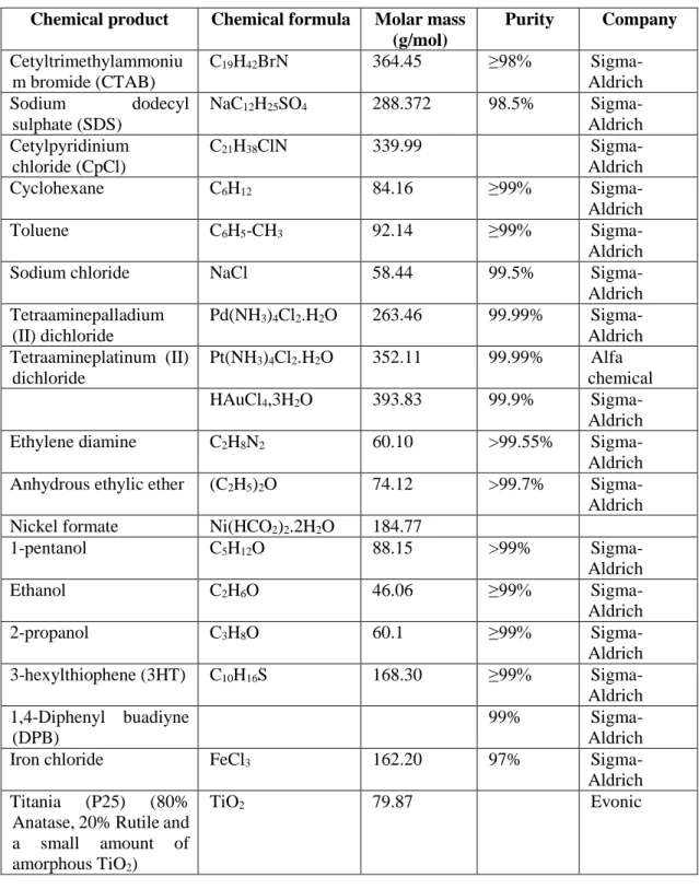
Fossil fuels such as coal, petroleum, and gas have been considered since the past century as major energy resources for electricity, transportation, industry, etc. In 2013, in Europe, 76% of the energy needs were still derived from fossil fuels, specifically 35 % from oil, 24 % from natural gas, and 17 % from coal (Figure 1.1).2 In France, the fossil fuel consumption is lower compared to EU because a large part of its energy need is supplied by nuclear energy (41%). As much as 49% of energy consumption in France is provided by fossil fuel (30% from oil, 14.5 % from natural gas, and 4.5 % from coal).
Figure 1.1 Energy consumption by source in Europe and France (2013)2
The utilization of fossil fuels is known to provoke various serious environmental problems, namely atmospheric pollution, greenhouse effect, global warming and depletion of natural resources. The combustion of fossil fuels releases greenhouse gases such as CH4, N2O, CO2, etc.3 The accumulation of those gases in the atmosphere leads to
an increase of the earth temperature, or so-called global warming, which generates many
35% 24% 17% 11% 7% 6% Europe oil natural gas coal nuclear hydro other renewable 30% 14.50% 4.50% 41% 9.50% 0.50% France
5 serious environmental problems. Furthermore, the reaction of those gases with water can produce sulfuric, carbonic, and nitric acid, which fall to earth as acid rains. The process of harvesting, processing, and distributing of fossil fuels can also have a harmful impact on the environment. For example, transport of coal requires the use of diesel-powered locomotives, and burning of coal generates large amount of fly ashes. In addition, fossil fuels are non-renewable resources and their amount is progressively reduced. Scientists and engineers will need to invest themselves in solving the issues generated by the utilization of fossil fuels. Greater investment in energy efficient technologies, low carbon technologies, renewable technologies, nuclear energy, and carbon capture and storage technologies is now needed. In transportation, increasing vehicle efficiency along with a gradual shift from conventional petroleum-fueled technology to fuel cells technology or rechargeable batteries for electrical cars is currently being a hot topic of research.
The other serious problem caused by the on-going industrialization and human activities is environmental pollution (water, air and soils). Water, which is really essential to our existence, is polluted by those activities. In the last few decades, it has become evident that water resources are limited. Approximately, from the total water in the hydrosphere (1,386 million cubic kilometers) only 2.5 % is fresh water, and only 0.26 % of this fresh water is accessible to humans (concentrated in lakes and river systems).4
Water is also fundamental for sustaining a high quality of life. Polluted water or water deficit may cause diseases and damages to the environment. The scarcity of clean water has progressively increased in the last 60 years. By 2025, the majority of population on earth will live under low water supply conditions.
To address these two big energy and environment issues, as material scientists, we can contribute in design of materials for application in energy generation (or storage) and water depollution.
I.2 Synthesis of nanomaterials
Nanosized materials, such as metal or bimetallic nanostructures, metal porous nanostructures, nanotubes, conjugated polymer nanofibers, are attracting growing interest because they often exhibit remarkable properties when compared to bulk materials.5 Exceptional magnetic, optical, electronic, and catalytic properties can be exploited for numerous technological applications in particular in energy generation and water
6 depollution.6–9 Properties such as catalytic, electrocatalytic, and photocatalytic activities could strongly depend on the size and shape of the nanomaterials.10 Therefore synthesis of nanomaterials that could exhibit well-controlled shapes and sizes has been explored to enhance their performances.11 Many approaches are currently developed to obtain metal and polymer nanostructures in a liquid phase.
The method of preparation of nanoparticles in aqueous medium involves reduction of metal precursor salt by a suitable reducing agent (such as sodium borohydride, ascorbic acid, formaldehyde and hydrazine). The reduction of metal precursor salt may also be carried out using UV-irradiation, microwave radiation and ionizing radiations like , X-rays or electron beams. Radiolytic reduction is a powerful method to synthesize metallic nanoparticles and nanostructures.12–16 The specificity of the radiation-induced reduction of metal ions into atom lies in generating radiolytic species of strongly reducing potential.
I.2.1 Radiolysis technique for the synthesis of nanomaterials
Radiolysis techniques have been successfully applied for the synthesis of several nanomaterials, including monometallic and bimetallic nanoparticles, polymers and composites.12,17 Concerning synthesis of metal nanoparticles, this method offers several advantages over the conventional chemical reducing technique such as: (1) mild conditions (atmospheric pressure and room temperature); (2) homogeneous reduction or polymerization (leading to nanomaterials with controlled and homogeneous size); (3) no additional reducing agents are used (as strong reducing species are formed by solvent radiolysis); and (4) most importantly in the case of bimetallic nanoparticles control of composition and structure (core-shell or alloy) by fixing the dose rate (which fixes the reduction kinetics).18
I.2.2 Principle of radiolysis
Radiolysis is the interaction of high-energy photons (γ-rays or X-rays) and atomic particles (electrons or ions beams) (so-called ionizing radiation) with matter. Radiolysis generates free radicals. The dose absorbed by the materials is expressed in grays (1Gy = 1 Jkg-1).19
7 The interaction of high-energy photon/atomic particles with a solvent such as water results in its excitation and formation of solvated electrons (es-) and radicals.19 The
processes of radical formation in the case of radiolysis of water are given in the reactions 1.1 to 1.4.
H2O H2O•+ + e− and H2O* (Equation 1.1)
H2O•+ + H2O •OH + H3O+ (Equation 1.2)
H2O* H• + •OH, H2 + O• (Equation 1.3)
e− + n H2O eaq− (Equation 1.4)
The hydrated/solvated electrons (e−s) and hydrogen radical (H•) are strong
reducing agents with the respective redox potentials: E°(H2O/eaq− ) = -2.87 VNHE (Normal Hydrogen Eelectrode) and E°(H+/H•) = −2.3 VNHE. These free radicals can reduce dissolved metal
ions down to the zero-valent state (complete reduction).
During radiolysis of water, hydroxyl radicals (HO•), which are very strong oxidative species [E0 (HO•/H
2O = +2.8 VNHE], are also formed. To avoid competitive
oxidation reactions which may limit or even prevent the reduction process of metals (in general), hydroxyl scavengers must be added in the solution prior to irradiation. Among these scavengers, primary or secondary alcohols (such as 2-propanol) molecules or formate ions, which also react with hydrogen atoms, are generally used.
(CH3)2CHOH + HO• (or H•) → (CH3)2C•OH + H2O (or H2) (Equation 1.5)
HCOO− + HO• (or H•) → COO•− + H2O (or H2) (Equation 1.6)
Due to their redox potentials [E0(CH3)2CO/(CH3)2C•OH) = −1.8 VNHE at pH 7,
and E0(CO2/COO•−) = −1.9 VNHE], the radicals formed by reactions (5) and (6) are almost
as powerful reducing agents as H• radicals to reduce the metal ions (M+) following the reactions below
M+ + (CH3)2C•OH → M0 + (CH3)2CO + H+ (Equation 1.7)
M+ + COO•− → M0 + CO2 (Equation 1.8)
When a chemical agent generally chosen as an electron donor (D) is added to the medium, its redox potential E0 (D+/D) in general is not negative enough to reduce directly isolated metal ions into atoms. Thus, it essentially reduces ions adsorbed on the nuclei,
8 which have more positive redox potential [reactions (1.9)–(1.11)]. Then a development process occurs, which results in larger clusters:
M+n + D → Mn + D+, (Equation 1.9)
Mn + M+ → M+n+1, (Equation 1.10)
M+n+1 + D → Mn+1 + D+. (Equation 1.11)
Therefore, the radiolysis technique can produce very small metal nanoparticles since solvent radiolysis leads to very strong reducing agents, which can effectively reduce metal ions into a zero-valent state metal.
I.2.3 Dose rate effect
In the case of metal nanoparticle synthesized by radiolysis (Figure 1.2), the nucleation and growth of the clusters depends on the dose rate, which fixes the reduction kinetics. At high dose rate, the reduction is very fast and followed by steps of coalescence of atoms separately created (Figure 1.2a). At low dose rate, the reduction is slower and association of M+ ions with atoms can be faster than the production rate of reducing radicals (Figure 1.2b). Therefore, the reduction of M+ ions occurs mostly in situ on
clusters already formed Mn+1+.
Figure 1.2. Nucleation and growth of clusters generated by radiolytic radicals at a) high and b) low dose rates.19
9 In the case of an irradiation-induced reduction process, when ions of two different metals are present in solution (figure 1.3), the competition reactions between those two metals will depend on the metal precursors and on the dose rate. At a low dose rate, the electron transfer occurs from the atoms of the less noble metal to the ions of the more noble metal, thus favoring the formation of bimetallic nanoparticles with a core-shell structure (the more noble metal being in the core). By contrast, at a high dose rate, the process of electron transfer from the less noble metal to the more noble metal can be prevented (due to fast reduction process) yielding alloyed clusters.20,21
Figure 1.3. Scheme of the influence of the dose rate on the competition between the inter-metal electron transfer and the coalescence processes during the radiolytic reduction of mixed metal ion solutions. High dose rates favor alloying, whereas low dose rates favor core-shell segregation of the metals in the nanoparticles.22
10 I.2.4 Synthesis of nanomaterials using templates
Synthesis of porous materials attracts a lot of interest for different applications: catalysis, electrocatalysis, sensing, drug delivery…To obtain a material with an organized and controlled porosity, a template synthesis is generally required. Different templates are available, and depending on their type and structure, a wide range of nanomaterials can be synthesized. There are three general steps for synthesis of nanomaterials using templates: (1) the template preparation, (2) the directed synthesis of the target material using the template, and (3) the template removal.23 The templates are classified into two types: hard templates, which are constituted of solid materials, and soft templates, which are formed by self-assembly of molecules.
Hard templates
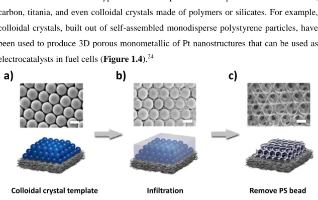
The most classical types of hard templates include porous aluminum oxide, carbon, titania, and even colloidal crystals made of polymers or silicates. For example, colloidal crystals, built out of self-assembled monodisperse polystyrene particles, have been used to produce 3D porous monometallic of Pt nanostructures that can be used as electrocatalysts in fuel cells (Figure 1.4).24
Figure 1.4 Schematic diagram of the fabrication process. (a) Self-assembly of a colloidal crystal template on GDL (gas diffusion layer). (b) Infiltration and pulse electrodeposition. (c) Removal of colloidal crystal template by soaking in toluene. Scale bar, 500 nm.24
Bimetallic nanostructures have been previously obtained using hard templates. For instance, porous AuPd structures have been successfully synthesized by successive deposition of Au and Pt inside porous silica SBA-15 (two dimensional hexagonal
a)
b)
c)
11 mesoporous silica) used as a hard template. The porous nanomaterial is then extracted by dissolution of silica (Figure 1.5).25
Figure 1.5 Preparation of mesoporous bimetallic Au–Pt with a phase-segregated heterostructure.25
Hard templates such as track-etch polycarbonate or polyester membranes and anodic aluminium oxide membranes have been employed for the synthesis of controllable nanorods, nanofibers, nanotubes of conjugated polymers such as PANI (polyaniline), PEDOT (poly(3,4-ethylenedioxythiophene), PPy (Polypyrrole), P3HT (poly(3-hexylthiophene)) etc.26,27 Other materials such as zeolites, silica-based mesoporous molecular sieves, metal oxides, polyoxometallates, solid porous materials can also be used as hard templates for the synthesis of nanostructures.26,28,29 Here, nanostructures grow inside the pores or channels of a membrane, in order to control their size and shape.
However, one of the major drawbacks of using hard templates lies on the extraction process, which requires the use of harsh chemical agents that can alter the synthesized nanostructures. An alternative way to obtain metal or polymer nanostructures is by using soft templates, based on the self-assembly of surfactants or amphiphilic block copolymers.30 Unlike with hard templates, the extraction process of these soft templates is very easy, as the synthesized materials can be extracted by simple addition alcohol (ethanol or 2-propanol) to the template and washing with the alcohol.
I.3 Soft templates: Swollen hexagonal mesophases
Thermotropic liquid crystals are molecular liquid crystals whose phase transitions are governed by temperature. By contrast, in lyotropic liquid crystals, made by a surfactant (or a mixture of surfactants in a solvent) the main control parameter is the concentration. Consequently, depending on their composition, different types of liquid
12 crystals with different symmetries, such as hexagonal, cubic, lamellar, etc.. can be formed. Swollen hexagonal mesophases are made of quaternary systems namely surfactant, brine, oil, and co-surfactant.
1.3.1 Surfactant
Surfactant is an abbreviation for surface active agent, which literally means active at the surface.31 Surfactant molecules are used to lower the free energy at the phase boundary. Surfactants are amphiphilic, which means that the molecules consist of at least 2 parts: a hydrophilic head group and a hydrophobic tail. The hydrophobic tail is usually a carboxylic chain.
Figure 1.6 Schematic illustration of a surfactant31
Surfactants can be classified depending on the nature of the polar head groups, which can be anionic, nonionic, cationic, or zwitterionic.
a. Anionic surfactants
Carboxylates, sulfates, sulfonates, and phosphates are polar groups found in anionic surfactants. The most commonly used counterions are sodium, potassium, ammonium, calcium, and various protonated alkyl amines. Figure 1.7 shows the chemical structure of sodium dodecyl sulfate (SDS), one the more common surfactant types belonging to this class.
13 b. Nonionic surfactants
Most non-ionic surfactants have a polyhydroxyl or polyether (consisting of oxyethylene units, made by polymerization of ethylene oxide) polar head.
Figure 1.8 An example of nonionic surfactant: Polyoxyethelene glycol (hydroxyl group).33
c. Cationic surfactants
The vast majority of cationic surfactants are based on the nitrogen atom carrying the cationic charge. Both amine and quaternary ammonium-based products are common.
Cetyl ammonium bromide (CTAB)
Cetyl pyridinum chloride (CpCl)
Figure 1.9 Two examples of cationic surfactants: cetyl ammonium bromide (CTAB)34 and cetyl pyridinum chloride (CpCl).35
d. Zwitterionic (amphoteric) surfactants
Zwitterionic (amphoteric) surfactants have both cationic and anionic centers attached to the same molecule. The cationic part is based on primary, secondary, or tertiary amines or quaternary ammonium cations. The anionic part can be more variable and include sulfonates, as in the sultaines CHAPS (3-[(3-Cholamidopropyl) dimethylammonio]-1-propanesulfonate) and cocamidopropyl hydroxysultaine. Betaines
14 such as cocamidopropyl betaine have a carboxylate with the ammonium. The most common biological zwitterionic surfactants have a phosphate anion with an amine or ammonium, such as phospholipids, phosphatidylserine, phosphatidylethanolamine, phosphatidylcholine, and sphingomyelins.
Figure 1.10 An example of zwitterionic (amphoteric) surfactant: CHAPS (3-[(3-Cholamidopropyl) dimethylammonio]-1-propanesulfonate) (anionic part).36
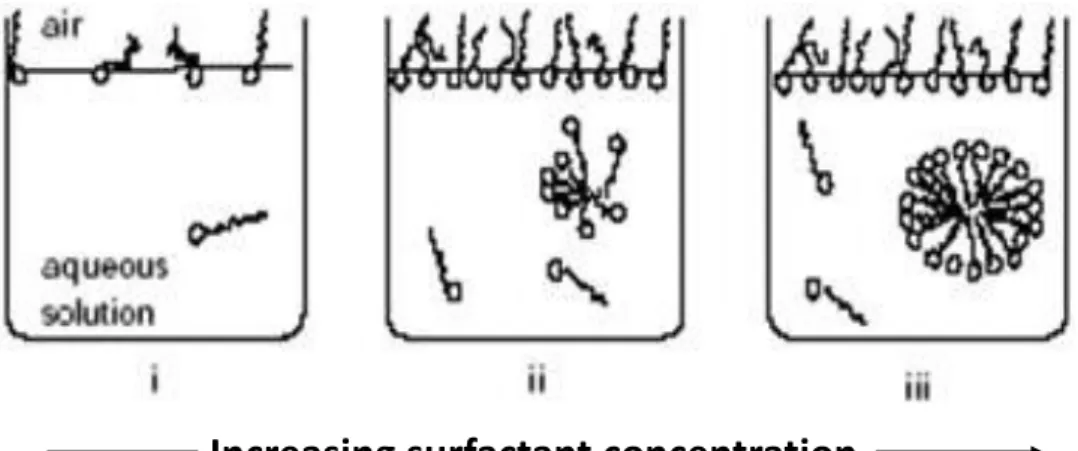
1.3.2 Surfactant self-assembly
Surfactant molecules cover the air/water interface where the hydrophobic tails point to air and the polar head remains in contact with water. When the surfactant concentration increases, surfactants molecules disperse in water. As the surfactant concentration increases, an aggregate called micelle is formed, where the hydrophilic head groups are in contact with water, and the hydrophobic tails are in the center of the aggregate and protected from the water. The driving force of micelle formation is the elimination of the contact between the hydrophobic tails and water. The radius of a micelle is equal to the elongated length of hydrophobic tail.37 The concentration where micelle starts to form is called critical micelle concentration (CMC). Different surfactants have different CMC values. Figure 1.11 presents the formation of a micelle in water.
15
Figure 1.11 Micelle formation37
Spherical micelles, as shown in figure 1.12, are one possibility of surfactant self-assembly. At higher surfactant concentrations or for different types of surfactant, different shapes of micelle may form. To understand the different structure of micelles that may form, it is convenient to introduce the critical packing parameter (CPP).
Figure 1.12 An illustration of spherical micelle (for dodecyl sulfate) emphasizing the liquid-like character with a disordered hydrocarbon core and rough surface.38
1.3.3 Critical packing parameter (CPP)
CPP is the most important parameter to determine the self-assembly behavior of surfactant molecules in a solvent and was proposed by Israelachvili and co-workers.39,40
CPP can be interpreted as the ratio between the cross-sectional area of the hydrocarbon part and that of the head group (the hydrophilic part). Estimating the CPP enables us to determine the surfactant molecular packing and preferred geometrical structure such as spherical micelles, cylindrical micelles, bilayers, reversed micelles, etc. The illustration
16 of CPP is given in Figure 1.13. Analysis of different geometrical shapes of aggregates, leads to simple rule presented to predict the shape of the micelles, as illustrated in Table 1.1.
Figure 1.13 The critical packing parameter (CPP) or surfactant number relates the head group area, a0, the extended length, lc, and the volume v of the hydrophobic part of a
surfactant molecules into dimensionless number CPP = v/(lca0).38
The interactions between the head groups in the aggregate are another factor that can affect the preferred geometrical structures. A strongly repulsive interaction between the head groups will drive an aggregate to the left in Fontell scheme, while the opposite applies for attractive interactions.
17
Table 1.1 Critical packing parameter (CPP) of surfactant molecules and preferred aggregate structures for geometrical packing reasons41
Critical packing parameter (v/a0lc) Critical packing shape Structures formed < 1/3 Spherical micelles 1/3 – 1/2
Hexagonal phase (cylindrical micelles)
1/2 - 1
Lamellar phase (sheet-like micelles)
≥ 1
*- Cubic
> 1
Reverse hexagonal phase (reverse cylindrical micelles)
18 Fontell scheme for surfactant self-assembly (Figure 1.14) clearly represents the normal and reverse mesophase formation.
Figure 1.14 Schematic representation of an amphiphilic molecule and normal and reverse type of surfactant self-assembled structures. L1, I1, H1, V1, and Lα represents
normal micelle, micellar cubic phase, hexagonal phase, bicontinuous cubic phase, and lamellar phase, respectively. V2, I2, H2, and L2α respectively represent reverse (inverted)
phases.42
1.3.4 Self-assembly in hexagonal mesophases
In a mixture of surfactant, water and oil, the micelles formation strongly depends on the ratio between the three components, as illustrated in the phase diagram shown in Figure 1.15.
Figure 1.15 A three component (water, oil, surfactant) phase diagram showing the formation of micelles and mesophases by the self-assembly of surfactants.43
19 Direct hexagonal phases consist of surfactant tubes regularly arranged on a triangular lattice in water. The structure is intermediate between a liquid phase and a crystalline phase. This is the reason why it is refereed as a liquid crystalline phase, or mesophase.
There are several factors affecting the formation of hexagonal mesophases: Polar head group interaction
Salt concentration Nature of the counterion Co-surfactant
The self-assembly of hexagonal mesophases is illustrated in Figure 1.16. A high concentration of surfactants in water (containing salt or not) will lead to the formation of micelles. When oil is added to the micelles, an unstable emulsion (oil drops in water) is formed. The addition of a small amount of co-surfactant (small molecule of alcohol that goes at the air/oil interface, as a surfactant molecule) will lead to the self-assembly in hexagonal mesophases. The co-surfactant helps to balance the interaction between the head groups of the surfactant molecules.
Figure 1.16 Formation of hexagonal mesophases
1.3.5 Characterization of hexagonal mesophases by Small Angle X-Ray Scattering (SAXS)
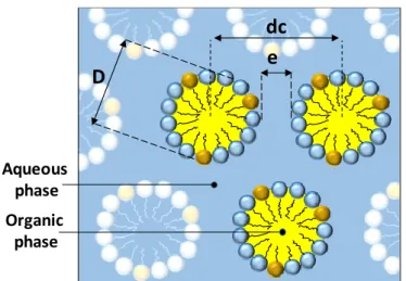
Characteristics of swollen hexagonal mesophases
There are several characteristic parameters of a hexagonal mesophase: Diameter of oil tube (D);
The distance between the center of the adjacent tubes (dc);
The water channel between the two adjacent tubes (e) (dc = D + e).
Water phase Oil/organic phase cyclohexane/ toluene Cosurfactant: n-pentanol
surfactant Water phase (cyclohexane/toluene)Oil
Micelles Microemulsion Hexagonal mesophase
Water phase Oil/organic phase cyclohexane/ toluene Cosurfactant: n-pentanol
surfactant Water phase Oil
(cyclohexane/toluene)
Micelles Microemulsion Hexagonal mesophase
Oil (Cyclohexane/ Toluene) Emulsion Water phase
20
Figure 1.17 Scheme of the cross-section of a hexagonal mesophase.
The formation of hexagonal mesophases can be confirmed by observation of their texture using a polarized optical microscopy. The pattern and orientation formed can clarify the formation of hexagonal mesophases. However, this technique cannot be used to quantify the geometric parameters of the mesophase. Small angle X-ray scattering (SAXS) are used to characterize the mesophases. The positions of the Bragg peaks define the symmetry of the mesophase. For hexagonal mesophases, the positions of the successive Bragg peaks are in the ratio of 1, √3, and 2.
Figure 1.18 Example of SAXS spectra of a hexagonal mesophase; a) 2D scattering pattern; b) scattering profile, scattered intensity as a function of the wavevector, obtained by integration of the scattering pattern shown in a; c) calculation of the ratio between the peak positions.
The distance between the center of two adjacent tubes (dc) isgiven by equation 1.1.
𝑑𝑐 = 4𝜋 (√3)∗𝑞0 (Equation 1.12) D dc e Aqueous phase Organic phase 0.2 0.4 0.6 0.8 1.0 101 102 103 104 I /abr.u n q (nm-1)
q
oq
1q
2 q1/q0= √3 (≈1.73) q2/q0= 2 a) b) c)21 where q0 is the position of the first Bragg peak as determined from the SAXS
spectrum.
The diameter of the oil tube (D) can thus be calculated using equation 1.2.
𝐷 = 2 ∗ 𝑑𝑐∗ √(√32𝜋) ∗ (1 − ∅𝑝) (Equation 1.13)
Here ϕp is the volume fraction of the polar phases comprising the aqueous phase,
the polar head group of the surfactant and cosurfactant molecules, relative to the total volume (equation 1.3).
∅𝑝 = 𝑉𝑎𝑞𝑢𝑒𝑜𝑢𝑠 𝑝ℎ𝑎𝑠𝑒+ 𝑉𝑝𝑜𝑙𝑎𝑟 ℎ𝑒𝑎𝑑 𝑜𝑓 𝑠𝑢𝑟𝑓𝑎𝑐𝑡𝑎𝑛𝑡+ 𝑉𝑝𝑜𝑙𝑎𝑟 ℎ𝑒𝑎𝑑 𝑜𝑓 𝑐𝑜−𝑠𝑢𝑟𝑓𝑎𝑐𝑡𝑎𝑛𝑡
𝑉𝑡𝑜𝑡𝑎𝑙 (Equation
1.14)
Where for CTAB, the volume of one polar head group is 102 Å3 and the volume of one polar head group of 1-pentanol is 20.3 Å3.
The thickness of water channel (e) can be calculated subtracting the distance between two adjacent tubes with the diameter of oil tube.
𝑒 = 𝑑𝑐 − 𝐷 (Equation 1.15)
1.3.6 Swollen hexagonal mesophases
One interesting property of hexagonal mesophases lies on their ability to be swollen. The tube diameter can be controlled by varying the ratio between the volume of oil to that of water (O/W). In our experiment, the volume of water is kept constant, while varying the volume of oil. To keep the mesophases stable, while increasing the volume of oil, the spontaneous curvature of the surfactant monolayer has to be varied concomitantly. This can be done by changing the ionic strength of the aqueous phase when using an ionic surfactant. Therefore, the salt concentration must be increased when increasing the O/W ratio.44 Figure 1.19 shows the scheme of the cross-section of a
22 hexagonal mesophase (a) and the tubes of mesophases arranged in a hexagonal lattice structures when the volume of oil is increased (b).
Figure 1.19 The scheme of the cross-section of hexagonal mesophases in a hexagonal lattice structures when the volume of oil is increased.
I.4 Synthesis of nanomaterials in hexagonal mesophases
Several nanomaterials including metal and conjugated polymer nanostructures have been successfully synthesized in the soft template hexagonal mesophases.16,17,45–49 Metals, which precursors are in general soluble in water, are synthesized in the confined aqueous phases of hexagonal mesophases. By contrast, the conjugated polymers, which monomers are soluble in oil, are polymerized in the oil phase of hexagonal mesophases.
I.4.1 Synthesis of porous metal nanostructures in the water phase of hexagonal mesophases
Swollen hexagonal mesophases can be doped with high concentrations of metal ions or complexes.44,50 The reduction of metal ions confined in the water phase has led to synthesis of 1D- 2D- or 3D-metal nanostructures such as Pd nanowires, Pd nanosheets Pd nanoparticles, Pd nanoballs, Pt nanoballs, PdPt nanoballs, AuPd core-shell.15,16,45,48,49,51 Those metals were synthesized by radiolysis (except Pd nanosheets which were synthesized through the reaction with CO) without any addition of reducing agents (the reducing species are induced by solvent radiolysis). Several factors can affect the shape of metal nanostructures formed in hexagonal mesophases such as the nature of
e
D
e
Swelling
Aqueous phasec
Oil phase
D’
surfactants
23 surfactants, the nature of metal precursors and the dose rate of radiation, which will be discussed in the following section.
I.4.1.1 The role of surfactants
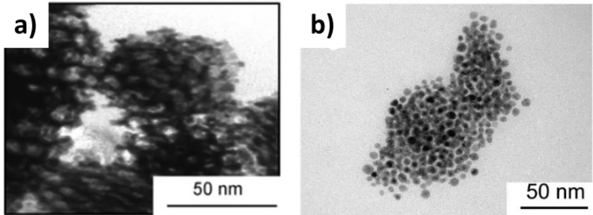
Previous studies in our group have shown that a specific cationic surfactant (cetyl trimethyl ammonium bromide, CTAB) is essential to obtain porous Pd and Pt nanoballs (formed by 3D-connected nanowires and synthesized in hexagonal mesophases).16,48 Other shapes of Pd and PdPt nanostructures were obtained using mesophases based on other cationic surfactants such as cetylpyridinium chloride (CpCl), cetylmethylammonium chloride (CTAC) and cetylpyridinium bromide (CpBr). Experiments conducted with CpCl gave small Pd particles with diameters around 3 nm.16 Nanostructures made of less ordered Pd or Pt parallel nanowires were obtained with CTAC and formation of nanoballs were not observed in this case. In the case of CPBr, the obtained nanostructures were spherical aggregates made by nanoparticles of diameter 3 to 4 nm.48
Figures 1.20 and 1.21 show TEM images of Pd nanostructures and PdPt nanostructures (with the atomic ratio Pd/Pt = 1/1) synthesized in hexagonal mesophases using different surfactants. Porous PdPt nanoballs can only be obtained using CTAB as surfactant. CTAB plays the role of structure-directing agent: It is known to favor formation of anisotropic nanostructures by preferential adsorption on (100) facets.52,53
Figure 1.20 Different shapes of Pd nanostructures synthesized with different surfactants: a) Pd nanoballs synthesized using CTAB; b) Pd nanoparticles synthesized using CPCl.16
24
Figure 1.21 TEM images of Pd-Pt nanostructures (Pd/Pt = 1:1) synthesized in hexagonal mesophases based on different cationic surfactants and containing 0.1 M of metal salts, (O/W=1.5): (a) CTAB, (b) CTAC and (c) CpBr after 48 h irradiation with dose rate of 1.85 kGy/h (total dose: 88.8 kGy) under N2 atmosphere.48
I.4.1.2 The role of the dose rate
The dose rate fixes the reduction kinetics. A slow reduction kinetics provided by low dose rate is necessary for the formation of nanoballs.16,45 Palladium nanowires
(Figure 1.22a) were synthesized using electron beams (which deliver a very high dose rate (48 kGy/h)) in hexagonal mesophases with CTAB as the surfactant (the same surfactant used to synthesize palladium nanoballs), whereas Pd nanoballs (figure 1.22b) were synthesized in mesophases using a low dose rate (1.85 kGy/h).16,45
25
Figure 1.22 TEM images of palladium nanostructures synthesized in hexagonal mesophases using different dose rates; a) Pd nanowires synthesized using electron beam with 48 kGy/h dose rate, b) Pd nanoballs synthesized using gamma radiation with 2.2 kGy/h dose rate.16,45
I.4.2 Synthesis of conjugated polymer nanostructures in the oil phase of hexagonal mesophases
Conjugated polymer nanostructures such as PDPB (Poly(diphenylbutadyine)and PEDOT (poly(3,4-ethylenedioxythiophene) for application in photocatalysis have been successfully synthesized in the oil phase of hexagonal mesophases.17,46,47,54 Depending on the ratio of oil to water (O/W) different diameter size/shapes of conjugated polymer nanostructures can be formed.
PDPB nanostructures were synthesized through a radical induced polymerization process. The formation of radicals is induced by either gamma irradiation or UV light. The diameter of the PDPB nanostructures can be tuned by controlling the O/W ratio in the soft template hexagonal mesophases. The higher the O/W ratio, the bigger the diameter of PDPB nanostructures is (Figure 1.23), as expected from a direct templating approach, since the synthesis takes place in the oil phase.17
26
Figure 1.23 Transmission electron micrographs of PDPB nanostructures prepared by UV-irradiation in mesophases with (a, b)O/W= 2.21, (c, d) O/W= 0.98, and (e, f) O/W= 0.72.17
PEDOT nanostructures were synthesized by a chemical polymerization process (by oxidation polymerization process using oxidant FeCl3). Depending on the O/W ratio,
different shapes of PEDOT nanostructures can be formed. Vesicle-like structures were synthesized in mesophases with O/W = 1.5, while PEDOT nanospindles were synthesized with O/W = 2.5 (Figure 1.24).47
Figure 1.24 TEM images of PEDOT vesicles (a) and PEDOT nanospindles (b).47
27 Synthesis of metal, polymer, and metal-polymer nanostructures in these soft templates and their applications will be discussed in chapters III, IV, and V. Several mono-, bi- and trimetallic nanostructures will be used as electrocatalysts for several reactions involved in fuel cells, while conjugated polymers are used as photocatalytic materials for water depollution
28
CHAPTER II
30
CHAPTER II
Experimental Part
All the chemical products and solvents used for the experiments are shown in Table 2.1
Table 2.1 List of chemical products and solvents and their specification
Chemical product Chemical formula Molar mass (g/mol) Purity Company Cetyltrimethylammoniu m bromide (CTAB) C19H42BrN 364.45 ≥98% Sigma-Aldrich Sodium dodecyl sulphate (SDS) NaC12H25SO4 288.372 98.5% Sigma-Aldrich Cetylpyridinium chloride (CpCl) C21H38ClN 339.99 Sigma-Aldrich Cyclohexane C6H12 84.16 ≥99% Sigma-Aldrich Toluene C6H5-CH3 92.14 ≥99% Sigma-Aldrich
Sodium chloride NaCl 58.44 99.5%
Sigma-Aldrich Tetraaminepalladium (II) dichloride Pd(NH3)4Cl2.H2O 263.46 99.99% Sigma-Aldrich Tetraamineplatinum (II) dichloride Pt(NH3)4Cl2.H2O 352.11 99.99% Alfa chemical HAuCl4,3H2O 393.83 99.9% Sigma-Aldrich Ethylene diamine C2H8N2 60.10 >99.55%
Sigma-Aldrich Anhydrous ethylic ether (C2H5)2O 74.12 >99.7%
Sigma-Aldrich Nickel formate Ni(HCO2)2.2H2O 184.77
1-pentanol C5H12O 88.15 >99% Sigma-Aldrich Ethanol C2H6O 46.06 ≥99% Sigma-Aldrich 2-propanol C3H8O 60.1 ≥99% Sigma-Aldrich 3-hexylthiophene (3HT) C10H16S 168.30 ≥99% Sigma-Aldrich 1,4-Diphenyl buadiyne (DPB) 99% Sigma-Aldrich
Iron chloride FeCl3 162.20 97%
Sigma-Aldrich Titania (P25) (80%
Anatase, 20% Rutile and a small amount of amorphous TiO2)
31
Rhodamine B C28H31ClN2O3 479.02 Fluka
Phenol C6H5OH 94.11
Sigma-Aldrich
Potassium hydroxide KOH 56.10 99.5%
Sigma-Aldrich
Nitrogen N2 28.0 Air liquid
Oxygen O2 32.0 Air liquid
Ultra-pure water H2O 18.0 Millipore
System, 18.2 MΩ cm
II.1 Preparation of hexagonal mesophases
Hexagonal mesophases were prepared following the previous published method.50,55 Initially, surfactant was dissolved in water (with or without salt). The mixture was vortexed for a few minutes, then put in the oven to reach the equilibrium (the temperature of the oven will depend on the type of surfactant; 50°C for CTAB, 30°C for SDS, and 40°C for CpCl). A certain amount of oil (here we used either cyclohexane or toluene) was added to the mixture under vortex. The addition of n-pentanol as cosurfactant led to a perfectly birefringent and transparent gel, a hexagonal mesophase.
II.1.1 Synthesis of metal nanostructures in the aqueous phase of hexagonal mesophases for application in fuel cells
Porous metal nanostructures such as PdPt, AuPd, AuPt, AuPdPt, and PtNi are synthesized in hexagonal mesophases through radiolysis technique. The precursors of metallic salts are dissolved in the aqueous phase. The ratio of oil to water in hexagonal mesophases can be adjusted, thus allowing us to control the pore size of metal nanostructures. In the synthesis of bimetallic PdPt, the ratio of oil to water in hexagonal mesophases is varied from 1.5 to 4.5. Hence, we expect to have different pore size for the PdPt bimetallic nanostructures.
a. Swollen hexagonal mesophases containing Pd and Pt
The mesophases are prepared following the procedure described above. Here we used CTAB as surfactant, n-pentanol as co-surfactant, cyclohexane as the oil phase, and water containing metallic salts and eventually NaCl. The total metallic salt concentration (Pd(NH3)4Cl2 and Pt(NH3)4Cl2)is kept at 0.1 M. The ratio of Pd to Pt is varied as shown in Table 2.2.
32
Table 2.2 Pd/Pt composition to prepare Pd, Pt, and Pd/Pt nanoballs
CTAB
Aqueous phase Cyclohe
xane (mL) n-pentanol (µL) water Pd/Pt composit ion Pd(NH3)4Cl2 (M) Pt(NH3)4 Cl2 (M) [NaCl] (M) 1.03 g 2 mL 100% Pd 0.1 0 0 2.98 240 100% Pt 0 0.1 0 2.98 240 (Pd50Pt50) 0.05 0.05 0 2.98 240 (Pd25Pt75) 0.025 0.075 0 2.98 240 (Pd75Pt25) 0.075 0.025 0 2.98 240
In order to obtain porous PdPt nanoballs with different pore sizes, the tube of hexagonal mesophases is swollen by varying the ratio of oil to water as shown in Table 2.3.
Table 2.3 Composition to prepare hexagonal mesophases with different oil to water ratios
CTAB
Aqueous phase Cycloh
exane (mL) O/W n-pentanol (µL) Water Total Pd-Pt salts (M) [NaCl] (M) [Total salt] (M) 1.03 g 2 mL 0.1 M 0 0.1 2.98 1.5 240 0.1 0.2 4 2 240 0.2 0.3 5 2.5 250 0.3 0.4 6.5 3.25 260 0.4 0.5 7.5 3.75 260 0.5 0.6 9 4.5 260
b. Preparation of hexagonal mesophases containing AuPd, AuPt, and AuPdPt Here we also used CTAB as surfactant, n-pentanol as co-surfactant, cyclohexane as the oil phase, and water containing metallic salts. The compositions of metallic salt, cyclohexane, and co-surfactant, (1-pentanol) are shown in Table 2.4.
33
Table 2.4 Composition to prepare hexagonal mesophases doped with Au, Pd, and Pt precursors.
CTAB
Aqueous phase cyclohex
ane (mL) n-penta nol (µL) V of water Au/Pd/Pt composition [Au(en)2] Cl3 Pd(NH3)4 Cl2 Pt(NH3)4 Cl2 1.03 g 2 mL Au5Pd95 0.005 0.095 0 2.98 240 Au10Pd90 0.01 0.090 0 2.98 240 Au5Pt95 0.005 0 0.095 2.98 240 Au10Pt90 0.01 0 0.090 2.98 240 Au5Pd70Pt25 0.005 0.070 0.025 2.98 240
The precursor of gold (ethylenediamine (gold(III) ([Au(en)2]Cl3)) is synthesized
following the previous published method.56 0.5 mL of ethylene diamine (purity >99.5%) diluted by 2.5 mL anhydrous ethylic ether (>99.7%) is added to a solution containing 0.5g of HAuCl4,3H2O and 5 mL of ether. A yellow gum precipitates. The upper solution is
discarded and the precipitate is dissolved in 0.5 mL of distilled water. The complex [Au(en)2]Cl3 precipitates with the addition of 5 mL of glacial ethanol. The process of
solubilization-precipitation is repeated 3 times. The yellow precipitate sample is dried on a filter Tamb, and kept in the dark.
c. Preparation of hexagonal mesophases containing PtNi
1.03 g of CTAB is mixed with 2 mL of water containing 0.085 M of Pt precursor (Pt(NH3)4Cl2) and 0.015 M of Ni precursor (Nickel nitrate (Ni(NO3)2 or Nickel formate
(C2H2NiO4)) under continuous vortex. The mixture is then placed in an oven at T= 50°C
for 1 h to reach reach a complete dissolution of the metallic salts. 2.98 mL of cyclohexane is added to the mixture under vortex leading to an unstable emulsion. The addition of ≈240 µL of n-pentanol as cosurfactant leads to a perfectly birefringent and transparent gel: a hexagonal mesophase.
34 Radiolytic synthesis of metal nanostructures in hexagonal mesophases
Hexagonal mesophases containing metallic complexes or salts are transferred into small vials, covered with rubber plastic septums, centrifuged for 15 minutes at 3000 rpm speed, and deoxygenized with N2 flow for 10 minutes. The samples are then exposed to
gamma irradiation for 24 hours at room temperature (the irradiation dose, 84 kGy, enables a complete reduction of the metal ions). Gamma irradiation is used as a technique to synthesize mono, bimetallic, and trimetallic nanostructures. The γ source located at Orsay is a 60Co gamma-facility of 7000 Curies with a maximum dose rate of 3.5 kGy h-1. Few samples are also prepared with electron beams at Elyse (Fast kinetics center in LCP) with a dose rate of 1062 kGy/h or 59 Gy/pulse (5 pulses/second). The color of the samples changes after irradiation from transparent to black. The nanomaterials are extracted from hexagonal mesophases using warm propanol, centrifuged and washed (with warm 2-propanol) several times to remove the excess of surfactant and salt.
II.1.2 Synthesis of conjugated polymer nanostructures in the oil phase of hexagonal mesophases
a Synthesis of conjugated polymer P3HT (poly(3-hexylthiophene))
Poly(3-hexylthiophene) (P3HT) nanostructures (here after called nano P3HT) were synthesized inside the oil phase of hexagonal mesophases. The hexagonal mesophases were prepared following the previously published method with some modifications. To prepare the hexagonal mesophases, 1.03 g of CTAB was first dissolved in 2 mL of sodium chloride 0.1 M and then, vortexed for a few minutes. The mixture was then let in an oven at 50°C for 1 h to form a transparent and viscous micellar solution. Then, 1 mL of toluene containing 54 µL of the 3HT monomer was added to the micellar solution under vortex. Subsequently, 2 mL of toluene containing 96 mg of FeCl3 was
added, and the mixture was vortexed for a few minutes. This led to an opaque unstable emulsion. The cosurfactant (20 µL of n-pentanol) was added dropwise and strongly vortexed until an orange, translucent and birefringent gel (a hexagonal mesophase) was formed. The polymerization of 3-hexylthiophene was induced by oxidation with FeCl3.
To avoid bulk polymerization, the monomer and oxidizing agent were never put together, but instead were dissolved in toluene separately and then added to the mixture during the mesophase formation.