HAL Id: tel-00945457
https://tel.archives-ouvertes.fr/tel-00945457
Submitted on 12 Feb 2014
HAL is a multi-disciplinary open access
archive for the deposit and dissemination of sci-entific research documents, whether they are pub-lished or not. The documents may come from teaching and research institutions in France or
L’archive ouverte pluridisciplinaire HAL, est destinée au dépôt et à la diffusion de documents scientifiques de niveau recherche, publiés ou non, émanant des établissements d’enseignement et de recherche français ou étrangers, des laboratoires
appliqué aux roues aubagées désaccordées
Biao Zhou
To cite this version:
Biao Zhou. Etude de l’amortissement piézoélectrique shunté appliqué aux roues aubagées désaccordées. Autre. Ecole Centrale de Lyon, 2012. Français. �NNT : 2012ECDL0055�. �tel-00945457�
Ecole Centrale de Lyon, Examinateur
Soutenu publiquement le 7 d´ecembre 2012,
M´
EMOIRE DE TH`
ESE
PR´
ESENT´
E POUR OBTENIR LE TITRE DE
DOCTEUR
DE L’´
ECOLE CENTRALE DE LYON
SP´
ECIALIT´
E: M´
ECANIQUE
´
ECOLE DOCTORALE DE M´
ECANIQUE DE LYON
(UCBL/INSA/ECL)
PAR
Biao ZHOU
´
ETUDE DE L’AMORTISSEMENT
PI´
EZO´
ELECTRIQUE SHUNT´
E APPLIQU´
E
AUX ROUES AUBAG´
EES D´
ESACCORD´
EES
devant le jury d’examen
F. LEBOEUF, Professeur, ´
L. PANNING-VON SCHEIDT, Professeur, Universit¨at Hannover, Rapporteur
G. KERSCHEN, Professeur, Universit´e de Li`ege, Rapporteur
L. LI, Professeur, Beijing University of Aeronautics & Astronautics, Examinateur
M. GRUIN, Ing´enieur, SNECMA, Examinateur
F. THOUVEREZ, Professeur, ´Ecole Centrale de Lyon, Directeur de th`ese
SUBMITTED FOR THE DEGREE OF
DOCTOR OF PHILOSOPHY
OF ´
ECOLE CENTRALE DE LYON
SPECIALITY: MECHANICAL ENGINEERING
´
ECOLE DOCTORALE DE M´
ECANIQUE DE LYON
(UCBL/INSA/ECL)
BY
Biao ZHOU
STUDY OF PIEZOELECTRIC SHUNT
DAMPING APPLIED TO MISTUNED
BLADED DISKS
Defended publicly on 7 december 2012
Doctoral Committee
F. LEBOEUF, Professor, ´Ecole Centrale de Lyon, Examiner
L. PANNING-VON SCHEIDT, Professor, Universit¨at Hannover, Reviewer
G. KERSCHEN, Professor, Universit´e de Li`ege, Reviewer
L. LI, Professor, Beijing University of Aeronautics & Astronautics, Examiner
M. GRUIN, Engineer, SNECMA, Examiner
F. THOUVEREZ, Professor, ´Ecole Centrale de Lyon, Thesis supervisor
I would like to express appreciation to those who have helped me through my doctoral studies. First of all, my most sincere gratitude goes to my supervisor Prof. Fabrice Thouverez and co-supervisor, Mr. David Lenoir, with whom it is my honor to work. It is them that gave me this unique opportunity to experience research in France. There is no doubt that this is one of the most exciting journeys in my life. I gratefully acknowledge their keen insights and clear guidance, as well as their patience, leading to a good completion of my doctoral life. I am pleased to acknowledge my colleagues in the D2S group. Special acknowledge is given to Aurelien Grolet and Emmanuelle Sarrouy for their helpful scientific discussion and friendly support. I really appreciate the companion of other chinese colleagues: Tianli Huang, Kai Zhang and Changwei Zhou in this laboratory.
I am grateful to Prof. Francis Leboeuf, who has honored me as the president of doctoral committee. I would like to also thank Prof. Lars Panning-von Scheidt, Prof. Ga¨etan Kerschen, Prof. Lin Li and Miss Marion Gruin for their review work of my thesis and presence in my defence.
Finally, I would like to deeply express my love and gratitude to my parents, my brother and Rong Li, who are always being there for me. Their understanding has encouraged me throughout my PhD.
Thanks go to the Ecole Centrale de Lyon and Chinese Scholarship Council for their financial supports on this research project.
This study deals with piezoelectric shunt damping in the mistuned bladed disks. Bladed disks are rich dynamical systems that are known to suffer from severe vibration problems. Blade mistuning is an issue of major concern since it is responsible for high cycle fatigue and failure risks. In the mitigation practice, additional damping is usually introduced into the structure to reduce vibration amplitudes. Here, we are interested in piezoelectric shunt damping applied into mistuned bladed disks.
In our proposed damping strategy, shunted piezoelectrics are attached onto the disk surface between adjacent blades in order to dissipate the disk mechanical energy. Consequently the blade vibration can be reduced due to the blade-disk coupling. This strategy is of engi-neering interest since piezoelectric transducers are placed outside of the main stream in turbomachinery. This idea is developed based on a lumped-parameter bladed disk model. Resonant shunt circuits are adopted. Both piezoelectric shunt damping and optimized piezoelec-tric mistuning are introduced to minimize the blade mistuning effect. Piezoelectric mistuning can be seen as a kind of damping mistuning; it is modeled as a small variation of the inductance value of each shunt circuit.
In reality the blade mistuning pattern is not constant in the long run. Due to various complexities, a perturbation of the blade mistuning pattern might result. In benefitting from the manageability and con-trollability of piezoelectric shunt circuits, an adaptive control strategy is developed to adjust the optimal piezoelectric mistuning pattern ac-cording to the perturbation. Numerical simulations reveal that a fine
An essentially nonlinear piezoelectric shunt circuit is proposed as prac-tical realization of nonlinear energy sink (NES). This piezoelectric-based NES is featured by nonexistence of preferential resonant fre-quency. It is therefore able to act in essence, as a passive, adap-tive, broadband vibration absorber, when integrated into a mechanical structure. A variable-coefficient harmonic balance method for quasi-periodic responses is devised. It helps gain insights into the complex dynamics of forced response when the coupled electromechanical sys-tem is under harmonic external forcing.
The appealing property of the piezoelectric-based NES enables it es-pecially suitable for applications in mistuned bladed disks since it is capable of adaptively interacting with each sector of mistuned bladed disks in a broadband fashion. Promising results obtained in the nu-merical studies further demonstrate this viewpoint.
Key words: piezoelectric shunt damping, blade mistuning, adaptive control, nonlinear energy sink.
Ce travail porte sur l’´etude d’amortissement pi´ezo´electrique shunt´e pour les roues aubag´ees d´esaccord´ees de turbomachines. Les probl`emes vibratoires sont de premi`ere importance pour les motoristes a´eronautiques et, parmi ceux-ci, les vibrations caus´ees par le d´esaccordage des aubes tiennent une place importante puisqu’elles sont `a l’origine des ph´enom`enes de fatigue oligocyclique et des risques de d´efaillance associ´es. L’usage de technologies d’amortissement est donc assez r´epandu pour r´eduire l’amplitude vibratoire. Ici, on s’int´eresse `a l’´etude de l’amortissement pi´ezo´electrique shunt´e appliqu´e aux roues aubag´ees d´esaccord´ees. Dans notre strat´egie, des patchs pi´ezo´electriques shunt´es sont attach´es sur la surface de la roue entre les aubes adjacentes afin de dissiper l’´energie m´ecanique de la roue. Par cons´equent, l’amplitude des aubes peut ˆetre r´eduite du fait du couplage entre les aubes et la roue. Cette strat´egie est d’int´erˆet pour l’ing´enieur car les transducteurs pi´ezo´electriques sont plac´es en dehors du flux principal des turboma-chines. Un mod`ele num´erique a ´et´e d´evelopp´e int´egrant des circuits pi´ezo´electriques shunt´es r´esonnants. L’amortissement pi´ezo´electrique shunt´e et un motif optimis´e de d´esaccordage pi´ezo´electrique sont tous les deux introduits afin de minimiser l’effet du d´esaccordage des aubes. En pratique, le d´esaccordage des aubes change au cours de la vie du moteur. Les raisons peuvent ˆetre multiple comme l’usure, des endommagement par impacts qui vont conduire in´evitablement `a une ´evolution du motif du d´esaccordage. En s’appuyant sur la strat´egie de contrˆole adaptatif, nous avont propos´e un shunt pi´ezo´electrique resonant capable de suivre l’´evolution de la structure au cours du temps. Les simulations num´eriques montrent qu’une bonne efficacit´e
Dans cette th`ese, une derni`ere strat´egie est propos´ee qui correspond `a la mise en place d’un syst`eme de pompage ´energetique nonlin´eaire bas´e sur les ´elements pi´ezo´electriques. Une fois int´egr´ees dans une struc-ture m´ecanique, il est donc en mesure d’agir en tant qu’amortisseur de vibrations, adaptatif et large bande. Une m´ethode num´erique, `a coefficient variables de balance harmonique, a ´et´e d´evelopp´ee afin de calculer les r´eponses quasi-p´eriodiques associ´es `a ce type de probl`eme. Ce dispositif de pompage ´energetique pi´ezo´electrique semble partic-uli`erement int´eressant dans le cadre des roues aubag´ees d´esaccord´ees, car il est capable d’interagir de fa¸con adaptative avec chaque secteur de la roue d´esaccord´e. Des r´esultats prometteurs ont ´et´e obtenus et illustrent d´emontrent ce point de vue.
Mots cl´es: amortissement pi´ezo´electrique shunt´e, roues aubag´ees,
Contents vii
Introduction 1
1 Dynamics of the bladed disk 5
1.1 Overview of turbomachinery, compressors and bladed disks . . . . 5
1.2 Vibratory phenomenons in bladed disk . . . 8
1.2.1 Aeroelastic aspect . . . 8
1.2.2 Mechanical sources of excitation . . . 10
1.3 Bladed disk modeling: cyclic symmetry strategy . . . 11
1.3.1 Cyclic components . . . 11
1.3.2 Spatial Fourier transform of matrices . . . 14
1.3.3 Continuity conditions in neighboring sectors . . . 16
1.4 Structure problems formulated with cyclic symmetry . . . 17
1.4.1 Modal analysis . . . 18
1.4.2 Forced response . . . 21
1.5 Vibration in mistuned bladed disks . . . 26
1.5.1 Mistuning sources . . . 26
1.5.2 Mistuning, coupling and mode localization . . . 29
1.5.3 Mistuning sensitivity . . . 31
1.5.4 Mistuning is always adverse? . . . 34
1.6 Vibration reduction in mistuned bladed disks . . . 36
1.6.1 Intentional mistuning . . . 36
1.6.2 Additional damping . . . 37
2 Conceptions of piezoelectric shunt damping 43
2.1 Overview of piezoelectric materials . . . 43
2.1.1 Constitutive equations . . . 44
2.1.2 Different transduction modes . . . 46
2.2 Piezoelectric shunt damping . . . 49
2.2.1 Piezoelectric-based system modeling: in the frequency do-main . . . 49
2.2.2 Piezoelectric-based system modeling: in the time domain . 57 2.3 Recent advances in piezoelectric shunt damping . . . 59
2.4 Conclusion . . . 64
3 Resonant shunt circuits applied into mistuned bladed disks 65 3.1 Introduction . . . 65
3.1.1 State-of-art: piezoelectric shunt damping in turbomachinery 66 3.1.2 Problem Statement and Research Objective . . . 69
3.2 Piezoelectric shunt damping in the tuned bladed disk . . . 71
3.2.1 Piezoelectric shunted bladed disk model . . . 71
3.2.2 Tuning design . . . 75
3.3 Blade mistuning . . . 77
3.3.1 Blade mistuning: deterministic viewpoint . . . 78
3.3.2 Blade mistuning: statistic viewpoint . . . 80
3.4 Piezoelectric mistuning . . . 82
3.4.1 Piezoelectric mistuning effect . . . 82
3.4.2 Piezoelectric mistuning pattern optimization . . . 83
3.5 Conclusion . . . 87
4 Adaptive control strategy for mistuned piezoelectric shunted blisks 89 4.1 Framework of the adaptive control strategy . . . 90
4.2 Estimation of random perturbation ∆δ . . . 92
4.2.1 Modeling gradual degradation of blade stiffness . . . 93
4.2.2 Online parameter estimation algorithm . . . 94
4.3 Response expansion . . . 97
4.5 Numerical simulation and results . . . 102
4.5.1 Performance of the adaptive control strategy . . . 103
4.5.2 Adaptive control strategy applied to time-varying mistuned bladed disks . . . 105
4.6 Conclusion . . . 106
5 Essentially nonlinear piezoelectric shunt circuit 107 5.1 Targeted energy transfer and nonlinear energy sink . . . 107
5.1.1 Configurations of nonlinear energy sink . . . 108
5.1.2 Analysis method and NES design . . . 109
5.1.3 Implementation of nonlinear energy sink . . . 111
5.2 Methods in nonlinear analyses . . . 112
5.2.1 Harmonic balance method . . . 114
5.2.2 Continuation technique . . . 118
5.3 Stability analysis . . . 122
5.3.1 Notion of stability . . . 123
5.3.2 Floquet theory . . . 125
5.3.3 Hill method . . . 127
5.4 Configuration of essentially nonlinear piezoelectric shunt circuit . 129 5.5 Nonlinear normal mode and free vibration . . . 132
5.5.1 Analytical study of nonlinear normal mode . . . 133
5.5.2 Numerical study of nonlinear normal mode . . . 136
5.6 Forced response . . . 141
5.6.1 Forced response by HBM & arc length continuation . . . . 142
5.6.2 Variable-coefficient harmonic balance method . . . 143
5.6.3 Nonlinear modal damping . . . 151
5.7 Conclusion . . . 154
6 Essentially nonlinear piezoelectric shunt circuits applied in blisks155 6.1 Multi-frequency TETs and resonance capture cascades . . . 156
6.2 Essentially nonlinear piezoelectric shunt circuits in tuned bladed disks . . . 159
6.2.2 Nonlinear normal modes . . . 164
6.2.3 Forced response . . . 167
6.3 Essentially nonlinear piezoelectric shunt circuits in mistuned bladed
disks . . . 168
6.4 Conclusion . . . 171
Conclusions and perspectives 173
Appendix A 176
Appendix B 178
.1 Linear approximation of the response . . . 178
.2 Gauss-Newton method for nonlinear least squares problems . . . . 179
Appendix C 181
List of Figures 183
Bladed disk structures are used in a number of propulsion and power generation applications. Bladed disks, as the name implies, consists of a central circular disk surrounded by blades. A bladed disk is featured by cyclic symmetry in the design phase. The structure can be divided into a number of identical substructures or sectors, which are arranged symmetrically around the central axis. In practice, however, the sectors are never perfectly identical due to manufacturing tolerances, material defects, and uneven wear in the operation. The small discrepancies between sectors are known as mistuning. It is well known that mistuning has a profound effect on the dynamic behavior of the bladed disk structure.
Vibration in mistuned bladed disks has received significant attention from the academic and industrial community in the last decades. In general, various research efforts in this domain can naturally fall into three categories.
The first category concerns the comprehensive understanding of the mistun-ing mechanism. Early research efforts on the phenomenological aspects of blade mistuning have been conducted in the area of structural dynamics. In fact, the subject matter is an interdisciplinary one requiring expertise in aerodynamics of cascades as well as structural dynamics of bladed disk assemblies leading to aeroelasticity of blades. The current trend is to include effects either previously absent or ignored from the early mistuned bladed disk analyses. For example, specific features of the aerodynamic damping and aerocoupling are now taken into account in the modeling of mistuned bladed disks.
The second category is more methodological in the field of structural dynam-ics. These research works focus on both a better representation of modeling and reducing computational cost. Studies on this subject are often initially mo-tivated by the request for phenomenological representation of mistuned bladed
disks. For example, nowadays, more and more investigations are performed on reduced-order models generating from large scale modern industrial finite element models of a full bladed disk. The reduced order models could reduce the com-putational models of the full bladed disk to manageable size, while retaining the model accuracy.
Finally, the last category focuses on blade vibration reduction. To this end, several schemes have emerged in the literature. One possibility is to act at the level of excitation to reduce their impact on the structure (e.g., symmetry break-ing excitations). One can also optimize the distribution of vibrational energy in the mistuned bladed disks and accordingly limit vibration levels in critical areas (structural optimization, or intensional mistuning). In the mitigation practice, additional damping is usually introduced into the bladed disk. In this thesis, we will pay special attention to the piezoelectric shunt damping in mistuned bladed disks.
Thesis outline
This thesis is dedicated to applying piezoelectric shunt damping into bladed disks in order to suppress blade mistuning effects. Chapter 1 is devoted to introducing dynamics and vibration phenomenons in bladed disks. The modeling methodol-ogy of tuned bladed disks is then illustrated in taking advantage of cyclic sym-metry property. Of particular interest is the vibration in mistuned bladed disks. A range of fundamental research issues are briefly presented.
In Chapter 2, conceptions of piezoelectric shunt damping are fully discussed. We present a detailed discussion on physical principles and constitutive mod-els of piezoelectric materials and structures. The concept of piezoelectric shunt damping is illustrated when piezoelectric materials are connected with classical shunt circuits, i.e. the resistive shunt circuit and resonant shunt circuit. Recent advances in this area will be also covered in the end of this chapter.
We propose a new piezoelectric damping strategy especially suitable for blisks, i.e., using resonant shunted piezoelectrics solely attached onto the disk, in Chap-ter 3. Both the piezoelectric shunt damping and piezoelectric mistuning effect will be utilized to achieve a maximum blade vibration reduction. Piezoelectric
mistuning can be seen herein, to some extent, as a kind of damping mistuning; it is modeled as a small variation of the inductance value of each shunt circuit. More specifically, an optimal piezoelectric mistuning, obtained by genetic algo-rithm optimization, could be introduced into a bladed disk with a given blade mistuning to achieve further blade vibration mitigation.
Chapter 4 presents an adaptive control strategy based on the piezoelectric shunt technique. This adaptive control strategy has focused on more realistic cases where the blade mistuning pattern is slowly time-varying. By taking ad-vantage of the controllability of piezoelectric shunt circuits, the piezoelectric mis-tuning pattern can be adjusted to keep “optimal” in terms of maintaining low blade vibration levels.
An essentially nonlinear piezoelectric shunt circuit is proposed in Chapter 5 as practical realization of nonlinear energy sink (NES). This piezoelectric-based NES is featured by nonexistence of preferential resonant frequency. It is therefore able to act in essence, as a passive, adaptive, broadband vibration absorber, when integrated into a mechanical structure. This appealing property enables it especially suitable for application in mistuned bladed disks.
In Chapter 6, essentially nonlinear piezoelectric shunt circuits are applied into mistuned bladed disks as an attempt. These essentially nonlinear shunt circuits are capable of adaptively interacting with each sector of mistuned bladed disks in a broadband fashion. Consequently, a sound damping performance can be expected.
Finally, main contributions of the research work presented in this thesis are summarized and a brief discussion on future directions for piezoelectric shunt damping in bladed disks is given at the end of this thesis.
Dynamics of the bladed disk
This chapter is dedicated to introducing dynamics and vibration phenomenons in bladed disks. Following a general overview on the functional environment of bladed disks, excitation sources and principal blade vibratory phenomenons are described. The modeling methodology of tuned bladed disks is then illustrated in taking advantage of cyclic symmetry property. Of particular interest is the vibration in mistuned bladed disks. A range of fundamental research issues will be briefly presented.
1.1
Overview of turbomachinery, compressors
and bladed disks
A turbomachine is a device that exchange energy with a fluid using continuously
flowing fluid and rotating blades [1;2]. Examples of these devices include aircraft
engines (see Fig.1.1) and wind turbine. Although aircraft engines have been built
and operated successfully for the past century, their inherent complexity still gives rise to unexpected behavior.
In a basic aircraft engine, air enters the front inlet and is compressed through a compressor. The compressor is made up of many blades that are attached to a disk mounted onto a shaft. These rotating blades compress the air and raise the pressure. Then the compressed air is mixed with sprayed fuel and an electric spark lights the mixture. The hot gases are expanded either through a turbine
Figure 1.1: The aircraft engine RB211-535E4 manufactured by Rolls-Royce (UK)
to generate shaft power or through a nozzle to create thrust. This shaft power, drives the compressor or the fan in turn, therefore bringing in a fresh air supply through the inlet. Aircraft engines are self sustaining machines. As long as fuel is provided they will keep operating.
The turbine and compressor components are mated by a shaft, since the former powers the latter. A single shaft aeroengine has only one shaft connecting the compressor and turbine components. A twin-spool aeroengine has two concentric shafts, a longer one connecting a low-pressure compressor (LPC) to a low pressure turbine (the low spool), which rotates inside a shorter, larger-diameter shaft. The latter connects the high-pressure turbine with the higher pressure compressor (HPC), which rotates at higher speeds than the low spool. A triples pool engine would have a third, intermediate-pressure compressor-turbine spool.
The more efficient, higher capacity axial flow compressor is widely used on
most gas turbines for high level of compression and thrust generation (see Fig.1.2a).
A stationary row in the form of inlet guide vanes is located at the start of the passage. Air or any other working fluid is first accelerated and then diffused to obtain the right pressure increment in an axial compressor stage. Rotating blades (airfoils) mounted on the disk impart kinetic energy to the fluid; stationary blades (stator vanes) then convert it into potential energy in the form of increased
(a) (b)
Figure 1.2: a)Low pressure axial compressor scheme of the Olympus BOl.1 tur-bojet; b)Diagram of an axial flow compressor.
each row of stationary and moving blades constituting a stage.
Bladed disks are therefore essential components of compressors and turbines.
A bladed disk assembly is represented in Figure 1.3. Vibration-induced fatigue
failure of rotating blades has been a problem of major concern to the designer [3].
Vibration reduction technologies are needed for high performance and lifespan requirement in modern aeroengines.
reference sector
In the following, the principal excitation sources and vibratory phenomenons in bladed disks will be discussed.
1.2
Vibratory phenomenons in bladed disk
There are several excitation sources, arising out of aerodynamic and structural environment in aeroengine, which can lead to vibration phenomenons of engine blades. The most common vibration problems of rotating bladed disks in op-eration include: a) resonant vibration occurring at multiple of rotation speed (integral order vibration); b) flutter, which is an aeroelastic instability (nonin-tegral order vibration), having the potential to escalate into larger and larger amplitude and leading to severe damage to the blades. The associate failures of engine blades are referred to as high cycle fatigue (HCF) failures. Both the reso-nance and flutter are induced by aerodynamic excitation. In addition, mechanical sources of excitation are also briefly referred.
1.2.1
Aeroelastic aspect
The principal sources of excitation in bladed disk is related to the aerodynamic loading acting on the blade. As remarked earlier, air flow entering the engine inlet meets with the rotating bladed disks and static obstructions (stator vanes) in its path from the inlet to the exhaust. The flow field inside the engine is inherently unsteady. Various of aerodynamic unsteady phenomenons, such as wakes, potential pressure disturbances, circumferential flow distortions, shocks in passages, secondary flows, coexist in either upstream or downstream of any rotor stage. The unsteady flow produces pressure variations, which is experienced by the spinning blades as a time-varying forces. A more detailed introduction is given
by Srinivasan [3] and numerous research efforts in this domain are presented by
Hall and Kielb [4]. In this section, we mainly introduce the aforementioned two
Resonant response
The flow conditions of air drawn through fan stages of an engine and delivered to compressors generally vary in space and time at any engine stage. Similar conditions prevail in the turbine stages. Therefore, blades experiencing pressures, velocities, incidence, temperatures, etc., that vary periodically in time. From the viewpoint of the structural dynamics, the key point relates to an accurate estimate of aerodynamic forcing and determining the resonant conditions under which the pattern of varying aerodynamic forces match any blade-disk modes both in time and space. If the resonant condition is met, the resulting vibration amplitude is controlled by attainable aerodynamic and structural damping in aeroengines. Therefore, the reliability of predicting resonant stresses depends upon the accuracy of prediction of aerodynamic forces, bladed disk modes and damping available in the operational environment. All these efforts are made to avoid resonant conditions based on a Campbell diagram, which will be introduced
in Section 1.4.
Flutter
Susceptibility of rotor blades to flutter instabilities is a major consideration in the design of turbomachines. A principal reason is that flutter is an aeroelas-tic instability leading to very high vibration amplitudes. Flutter is caused by an interaction between the blade vibratory motions and the aerodynamic forces resulting from these motions. In the instable condition the aerodynamic forces feed energy into the blade, and thus stresses escalate with each sequential cycle of vibration. Vibration amplitude of blade can thus cumulate. Unless the energy dissipated by aerodynamic and mechanical damping matches the energy input, blade vibration will not be limited, which can result in large amplitude vibration and potentially lead to rapid failure.
Because of this, the blades are designed carefully within known parameters to avoid flutter. However, usually both the unsteady aerodynamics and the me-chanical properties of the bladed disks in aeroengines are not fully understood, flutter can only be kept under control through detailed testing. An important feature of flutter is that the resulting vibration is nonintegral and therefore the
frequency-speed characteristic does not “ride” the engine order line in the Camp-bell diagram. On the contrary, resonant conditions at an integral order are met when the frequency speed characteristic goes across the engine order line. When it departs from the engine order line, then the aeroelastic instability of flutter could take place.
1.2.2
Mechanical sources of excitation
In addition to the aerodynamic sources, there also exist mechanical sources of excitation that can produce forces at frequencies that may lead to forced vibration in an individual blade mode or a system mode. For example, foreign object damage occurs when either the low compressor blades are impacted by a bird (or a block of ice) at take-off/landing, or if a downstream blade is impacted by debris of an upstream blade. Whatever the case is, the metal pieces must be contained by the casing. Fan blade-off and bird ingestion are two tests used in the certification process of an engine.
Among various effects of mechanical excitation, the nonlinearity caused by contact interface are receiving more and more attention. In fact, there are non-linearities caused by contact at shroud interface, at dovetail attachments for
in-serted blades [5; 6], and caused by the blade-tips/casing contact phenomenons
[7; 8]. A number of emerging studies in this area are beyond the scope of this
work. Hence they are not listed here.
Above all, vibrations of bladed disks occur in an aerodynamical environment in aeroengines. Therefore, apart from structural dynamic characteristics, significant advances in the aerodynamic aspect is also required for the prediction of blade vibration risks. Next we will turn to the structural dynamic aspect of bladed disks.
1.3
Bladed disk modeling: cyclic symmetry
strat-egy
The bladed disk modeling methodology takes advantage of the cyclic symmetry property in this periodic structure. A structure is said to present cyclic symmetry when it is composed of a number of geometrically identical substructures, i.e.
sectors. For instance, Fig.1.3depicts a full model of bladed disk and its reference
sector.
The assumption of perfect cyclic symmetry greatly simplifies the tuned bladed disk vibration analysis. It enables equations of motion to be uncoupled by spatial Fourier decomposition. Instead of analyzing the full bladed disk as a whole, we could therefore have an insight of the full structure by only investigating the dynamic behavior of the reference sector. For more details, readers are referred
to early research efforts by Thomas [9], Wildheim [10] and Sternchuss [11].
1.3.1
Cyclic components
Let’s consider a cyclic structure that is composed of N sectors numbered from 0 to N −1. It is generated by rotation of the reference sector with a phase difference
α = 2π/N . A vector uj represents a certain quantity (displacements, forces etc.)
in physical coordinates for the jth sector. As usual, u
0 stands for the quantity in
the reference sector. According to the cyclic symmetry condition, we have:
uN +j = uj, j = 0, 1, · · · , N − 1 (1.1)
From the theory of cyclic components, the vector uj in physical coordinates
for all N sectors may be expressed as a linear combination of the corresponding
quantity ˜u0 in cyclic coordinates for the reference sector as:
uj = N −1 X k=0 ˜ uk0eijkα, i2 = −1 (1.2) The amplitude ˜uk
0 is named cyclic component of harmonic order k on the
that a quantity is represented in cyclic coordinates. For each cyclic component of harmonic order k, the inter-sector phase difference is fixed and equals kα.
The cyclic components ˜uk
0 is defined as a function of physical coordinates uj:
˜ uk0 = 1 N N −1X j=0 uje−ijkα (1.3)
Transforms (1.2) and (1.3) are (inverse) discrete spatial Fourier transforms, in
essence. Since the physical quantity u is considered in the valued form, a real-valued matrix presentation of the discrete spatial Fourier transform is preferable for convenience. The complex cyclic components could be written as:
˜
uk0 = ˜uk,c0 + i˜uk,s0 (1.4)
A real form of cyclic representation is introduced as: ˜
u = [˜u00 · · · ˜uk,c0 u˜k,s0 · · · ˜uN/20 ]T (1.5)
where the last term ˜uN/20 only exists if N is even.
The physical representation is:
u = [u0 · · · uj · · · uN −1]T (1.6)
Since cyclic components are represented by trigonometric series, the physical
quantity uj for jth sector can be expressed as:
uj = 1 √ Nu˜ 0 0+ r 2 N κ X k=1 h ˜ uk,c0 cos(jkα) + ˜uk,s0 sin(jkα) i + (−1) j−1 √ N u˜ N/2 0 (1.7)
In the above expression, the harmonic index k varies from 0 to κ. κ is defined as:
κ = (
N/2 − 1 if N is even;
(N − 1)/2 if N is odd. (1.8)
discrete spatial Fourier transform:
u = [E]˜u (1.9)
The unitary Fourier matrix [E] is defined as:
[E] = √1 N 1 √2 0 · · · 0 1
1 √2cosα √2sinα · · · √2sinκα −1
1 √2cos2α √2sin2α · · · √2sin2κα 1
... ... ... ... ...
1 √2cos(N −1)α √2sin(N −1)α · · · √2sin(N −1)κα (−1)N −1
(1.10)
where the last column only exists if N is even.
Similarly, the cyclic components could also be expressed with the inverse matrix of [E]. Let’s note that the matrix [E] is orthonormal, or unitary, such
that [E]T[E] = I, where I is an identity matrix of size N and the superscript (.)T
denotes the transpose. This implies that [E]T = [E]−1. We have:
˜
u = [E]−1u = [E]Tu (1.11)
where the corresponding backward transform from physical to cyclic coordinates could also be given by the following series of relations:
˜ u00 = √1 N N −1X j=0 uj (1.12) ˜ uk,c0 = r 2 N N −1X j=0 cos(jkα)uj ˜ uk,s0 = r 2 N N −1 X j=0 sin(jkα)uj ˜ uN/20 = √1 N N −1X j=0 (−1)j−1u j (1.13)
In the rest of this thesis, the real-valued form of spatial Fourier transform is
preferred. The physical representation u = {uj, j = 0, · · · , N − 1} and cyclic
representation ˜u0 = {˜u00, ˜u k,c
0 , ˜uk,s0 , ˜u
N/2
0 , k = 1, · · · , κ} are equivalent. Due to the
fact that the cyclic components contain the complete set of admissible circumfer-ential mode shapes of the cyclic assembly, this transform is not an approximation, but an accurate description of the global system behavior.
1.3.2
Spatial Fourier transform of matrices
In finite element formulations (Ritz-Galerkin procedure), the continuous field u is discretized which leads to a physical vector of degree of freedom (DOF) U on the
full bladed disk structure. We can gather all the DOFs as a series of vectors Uj
defined on jth sector. Since it is assumed the full bladed disk has a perfect cyclic
symmetry, it is possible to compute cyclic components defined on the reference
sector by the spatial Fourier transform. Let U = [U0, U1, · · · , UN −1]T, we have:
˜
U = ([E]T ⊗ In)U (1.14)
where ˜U is the vector in cyclic coordinates in the form of
˜
U = [ ˜U00, · · · , ˜U0k,c, ˜U0k,s, · · · , ˜U0N/2]T (1.15)
As aforementioned, the last term ˜U0N/2 only exists if N is even. Inis n×n identity
matrix and n is the number of DOFs in each sector. The symbol ⊗ denotes the Kronecker product. U could also be recovered by the inverse discrete Fourier transform:
U = ([E] ⊗ In) ˜U (1.16)
At this stage, the physical discretized fields defined in two adjacent sectors
are assumed disjoint. The continuity condition will be discussed in Section 1.3.3.
The spatial Fourier transform of a field, either continuous or discretized, only requires a periodic distribution of points. A matrix representation of the operator that acts on the physical field is to be examined below.
results from the assembly of the disjoint sector matrices: A = A0 · · · 0 · · · 0 ... ... ... ... 0 · · · Aj · · · 0 ... ... ... ... 0 · · · 0 · · · AN −1 (1.17)
The bladed disk is said to be tuned when all sectors share exactly the same set of mechanical properties, i.e. perfect cyclic symmetry. In this particular case, the
matrix A could be derived from the submatrix A0 associated with the reference
sector so that:
A = IN ⊗ A0 (1.18)
The spatial Fourier transform could then be applied to the the matrix A: ˜
A = ([E]T ⊗ In)(IN ⊗ A0)([E] ⊗ In) (1.19)
Taking into account properties of the unitary Fourier transform matrix [E],
we have a block-form matrix of ˜A:
˜ A = ˜ A0 · · · 0 · · · 0 ... ... ... ... 0 · · · A˜k · · · 0 ... ... ... ... 0 · · · 0 · · · A˜N/2 (1.20)
Blocks in ˜A depend on the mechanical properties of the reference sector A0
and the harmonic index k: ˜ A0 = A˜N/2 = A0 (1.21) ˜ Ak = " A0 0 0 A0 # , k = 1, · · · , κ (1.22)
imaginary part of the spatial Fourier harmonic with index k.
The property exhibited in this section reveals that in the tuned bladed disk, structure matrices do not couple the Fourier harmonics to each other if sectors in the full bladed disk are considered disjoint. Next, it is necessary to define continuity conditions between the reference sector and its neighboring sectors.
1.3.3
Continuity conditions in neighboring sectors
Continuity conditions are imposed on the interface of the reference sector. Fig.1.4
gives an illustration of interfaces between the reference sector and its neighboring
sectors. Let us consider that an arbitrary vector U0 defined on the reference
sector could be partitioned into the DOFs on the left interface lU
0, on the right
interface rU
0 and interior DOFs iU0:
U0 = [lU0 rU0 iU0] (1.23) sector 1 right interface left interface sector 0 rU1 lUN− 1 lU0 rU0 iU0 sector N-1
Figure 1.4: Illustration of interfaces of the reference sector
Continuity conditions on interfaces of the reference sectors with the neighbor-ing sector numbered 1 and N − 1 are given by:
lU
0 = rU1 (1.24)
rU
0 = lUN −1 (1.25)
Substituting the relation in Eq. (1.3) into Eq. (1.24) and Eq. (1.25), one could
index k:
lU˜k
0 = rU˜0keikα (1.26)
rU˜k
0 = lU˜0kei(N −1)kα (1.27)
These propagation equations in cyclic coordinates allow to relate the DOFs on the left interface to that on the right interface. They are completely equivalent.
Eq. (1.26) is then adopted to eliminate the DOFs on the left interface. Once
again, we can write continuity conditions in the real-valued form: • k = 0, lU˜0 0 =r U˜00 (1.28) • k = 1, · · · , κ, " lU˜k,c 0 lU˜k,s 0 # = " coskα sinkα −sinkα coskα # " rU˜k,c 0 rU˜k,s 0 # (1.29) • k = N/2, lU˜N/2 0 = −rU˜ N/2 0 (1.30)
With inter-sector continuity conditions, it enables to carry out the bladed disk structure analysis based on the reference sector. This will considerably reduce the size of vibration problems. In the next section, the method of formulating bladed disk structure problems with cyclic symmetry is to be presented.
1.4
Structure problems formulated with cyclic
symmetry
Consider a discrete structure problem of the bladed disk in physical coordinates:
M ¨U (t) + C ˙U (t) + KU (t) = F (t) (1.31)
where M , C and K are mass matrix, damping matrix and stiffness matrix, re-spectively. U (t) is the vector of displacement and F (t) denotes the external
excitation.
As described in the precedent sections, the physical quantities U and F could
be reformulated in cyclic coordinates according to the relation in Eq. (1.14).
Consequently, the problem presented by Eq. (1.31) in physical coordinates could
be reformulated in cyclic coordinates. This reformulation consists of a set of independent subproblems for each harmonic order k:
˜ MkU¨˜k
0(t) + ˜CkU˙˜0k(t) + ˜KkU˜0k(t) = ˜F0k(t) (1.32)
For each subproblem corresponding to harmonic order k, the continuity
con-ditions defined in Eq. (1.28), (1.29) and (1.30) should be taken into account.
After resolving each subproblem, the complete response U (t) could be
ob-tained by the superposition of all cyclic components (see Eq. (1.16)). We discuss
the details of the modal analysis and the force response respectively in this sec-tion.
1.4.1
Modal analysis
The modal analysis of a tuned bladed disk is realized through solving the eigen-value problems defined in the reference sector for each harmonic index k:
( ˜Kk− ω2M˜k) ˜X0k = 0 (1.33)
For the harmonic index k = 0 and k = N/2, the system matrix in cyclic
coordinates are of size n (see Eq. (1.21)) and the corresponding modes are
non-degenerate; for the other harmonic index k = 1, · · · , κ, system matrices in cyclic
coordinates are of size 2n (see Eq. (1.22)). The rows in system matrices are
de-coupled into the real and imaginary part of the spatial Fourier harmonic. Note that these system matrices are symmetric and that their two diagonal blocks are identical. The eigenvalue problems belongs to a degenerate class of structural eigenvalue problems, which will yield pairs of real eigenvalues. The circumferen-tial positioning of mode shapes pertaining to double harmonics is arbitrary. As a result, these mode shape pairs can also be represented by complex,
Mode shapes of the full bladed disk are obtained by applying the relation
Eq. (1.16) to the eigenmode ˜Xk
0 in the cyclic coordinates. Let’s note that each
subproblem for harmonic index k is independent. For practical consideration, it is possible to only solve the subproblems with some particular harmonic index k. Then the full blade-disk mode with respect to harmonic index k is reconstructed separately: Xk = ([E]0⊗ I n) ˜X00 k = 0; ([E]k⊗ I n) ˜Xk,c 0 ˜ X0k,s ! k = 1, · · · , κ; ([E]N/2⊗ I n) ˜X0N/2 k = N/2. (1.34) with [E]0 = √1 N 1 1 1 ... 1 [E]N/2 = √1 N 1 −1 1 ... (−1)N −1 (1.35) [E]k = r 2 N 1 0 ... ... cos(jkα) sin(jkα) ... ... cos(N − 1)kα sin(N − 1)kα
It is a classical strategy to plot the eigenfrequency of a tuned bladed disk with respect to the number of nodal diameters (harmonic index k). A typical
frequency/nodal diameters plot is shown in Fig. 1.5 for a monobloc disk with 36
blades [13].
As remarked earlier, blade-disk mode can be represented by counter-rotating waves propagating in the circumferential direction. Blade vibration is thus related to energy transfer among consecutive sectors in the blade-disk structure. In most cases, the structure coupling, particularly blade-disk coupling, plays the key role as the dominant mechanism for inter-sector energy transfer. The blade-disk coupling strength can be examined in the frequency/nodal diameters plot
0 2 4 6 8 10 12 14 16 18 0 50 100 150 200 250 300 Frequency (rad/s)
Number of nodal diameters veering #1
veering #2
Figure 1.5: Example of Frequency/ Nodal diameters diagram
blade-dominated mode
Modes dominated by blade motion tend to appear as horizontal lines in the plot. They feature little disk motion and thus they have weak inter-blade coupling. This feature tends to confine the strain energy to the inter-blades. There may be numerous blade-dominated modes corresponding to moderate or high nodal diameters. These regions of high modal density are referred to as clustered mode area.
disk-dominated mode
The modal stiffness of a disk increases rapidly as the number of nodal diameters is increased. So disk-dominated modes appear as slanted lines in this plot. In disk-dominated modes, the inter-blade coupling is high enough so that the strain energy spreads over the blades and the disk.
There are several regions where the disk and blade modes appear to veer
away from each other, as indicated by “veering” in Fig. 1.5. For example, in
the veering area #2, blade-dominated modes at 5 nodal diameters loses its blade characteristics through the veering, becoming disk-dominated mode at 6 nodal diameters; on the other hand, the disk-dominated mode at 5 nodal diameter
gains more blade participation through the veering, becoming blade-dominated at higher nodal diameters. Modes in the veering regions tend to be featured by mixed disk-blade motion. Therefore, the blades will have significant vibration response if these modes are excited. There is also a mechanism for transferring energy between blades through the disk. This combination of conditions can lead to the blade vibration energy being localized in a few blades when blade
mistuning is present [14]. Blade mistuning will be discussed in detail in Section
1.5.
The relationship between the veering and inter-blade coupling has been
in-vestigated extensively [15–17]. From curve veering theory, it is known that the
strength of the blade-disk interaction, and thus the inter-sector coupling, is a function of veering curvature. If the interaction between disk-dominated and dominated motion is negligible, then the disk-dominated and the blade-dominated frequency curves will appear to “pass through” each other (veering
#1 in Fig. 1.5). The veering is therefore extremely sharp with high curvature. In
contrast, a lower-curvature veering indicates a higher level of modal interaction,
and accordingly, stronger inter-sector coupling (veering #2 in Fig. 1.5).
The veering theory has been further developed by Bladh et al. [18] to
ob-tain continuous natural frequency curves. The continuous veering plot offers a tool to better determine the type of the examined blade-disk modes. Thus, the inter-sector coupling strength can be quantified by examining the veering char-acteristics.
Another benefit of examining blade-to-blade coupling through the disk is that it enables one to affect the blade response through variation of the disk parameters
[19]. This finding also raise possibility of introducing some kind of damping to
the disk for the purpose of affecting the blade response. For example, friction rings are usually arranged inside the integral blisk grooves in order to enhance the structural damping.
1.4.2
Forced response
When it comes to compute the response of a tuned bladed disk under an external excitation, a similar procedure as described in the modal analysis is adopted.
This procedure consists of three typical steps:
• Decomposition of the external excitation into spatial Fourier harmonics; • Resolving subproblems for each harmonic;
• Reconstructing the displacement vector of the full bladed disk in physical coordinates from the cyclic coordinates.
First, the external excitation F (t) is decomposed into its spatial Fourier
com-ponents using the Fourier transform Eq. (1.14). This transform allows to obtain
the cyclic component ˜Fk
0 of external force defined in the reference sector using
the physical representation Fj acting on each sector:
˜ F00 = √1 N N −1X j=0 Fj (1.36) ˜ F0k,c = r 2 N N −1 X j=0 cos(jkα)Fj ˜ F0k,s = r 2 N N −1 X j=0 sin(jkα)Fj ˜ F0N/2 = 1 √ N N −1X j=0 (−1)j−1Fj
Following the spatial Fourier decomposition, we can solve a series of subprob-lems corresponding to each harmonic component:
• k = 0, ( ˜ M0U¨˜0 0(t) + ˜C0U˙˜00(t) + ˜K0U˜00(t) = F˜00(t) lU˜0 0 = rU˜00 (1.37)
• k = 1, · · · , κ, ˜ Mk" ¨˜U k,c 0 (t) ¨˜ U0k,s(t) # + ˜Ck" ˙˜U k,c 0 (t) ˙˜ U0k,s(t) # + ˜Kk" ˜U k,c 0 (t) ˜ U0k,s(t) # =" ˜F k,c 0 (t) ˜ F0k,s(t) # " lU˜k,c 0 lU˜k,s 0 # = " coskα sinkα −sinkα coskα # " rU˜k,c 0 rU˜k,s 0 # (1.38) • k = N/2, ( ˜ MN/2U¨˜N/2 0 (t) + ˜CN/2U˙˜ N/2 0 (t) + ˜KN/2U˜ N/2 0 (t) = F˜ N/2 0 (t) lU˜N/2 0 = −rU˜ N/2 0 (1.39)
After resolving each subproblems, the complete forced response U (t) could be obtained by the superposition of all cyclic components:
U = ([E] ⊗ In) ˜U (1.40)
Equivalently, this principle of superposition could be expressed by trigono-metric series: Uj = 1 √ N ˜ U00+ r 2 N κ X k=1 h ˜ U0k,ccos(jkα) + ˜U0k,ssin(jkα)i+(−1) j−1 √ N ˜ U0N/2 (1.41)
Engine order excitation
The primary form of excitation in the analysis of forced response in
turbomachin-ery is that of engine order excitation. As remarked in Section 1.2.1, this forcing
condition occurs due to the fact that the rotors are rotating through a unsteady flow that is non-uniform in the circumferential direction. The non-uniformity of the flow stems from the multiple obstructions in the flow field. Each blade on the rotating assembly experiences these spatial variations in the steady flow as time-varying and therefore responds by vibrating with frequencies that are directly related to the speed of rotation.
The forcing function is characterized by a frequency which is an integer mul-tiple of the rotation speed; on the other hand, it has also a characteristic shape since it is applied simultaneously to all the blades around the assembly. By per-forming a spatial Fourier transform of the flow field it may be broken into its spatial harmonics. In assuming linear dynamics, the response of the assembly to each of these harmonics can be analyzed separately. An engine order excitation is therefore assumed, which is harmonic in time and differs only in phase from blade to blade. The forcing function of an engine order EO with excitation frequency ω on blade j can be expressed as:
Fj = Fampeiωtei2πEO
j−1
N (1.42)
which is a traveling wave excitation of amplitude Famp traveling in the positive j
direction with wave speed:
ωN 2πEO
The advantage of examining individually the spatial harmonics of the excita-tion is that each harmonic excites only modes with a harmonic index that matches
the engine order. The relationship between the number of nodal diameters (Nd)
of the excited mode and the excitation order p (excitation harmonic EO multi-plied by the number of obstacles (stator blades) in the upstream of the considered
bladed disk) is determined analytically by: Nd= |kN − p| with 0 ≤ k ≤ N/2 and
0 ≤ |kN − p| ≤ N/2. For example, the nodal diameter 3 mode shown in Fig. 1.5
would be excited by engine order excitation EO = 3. If there are 36 blades in the system, this mode would be excited by an excitation of order p = 33, and p = 39, and so forth. This relationship could also be intuitively illustrated in a
Zig-zag diagram [10].
Campbell diagram
Let’s turn to the realistic case where the bladed disk is rotating at speed Ω. As remarked above, the engine order EO excitation will excite all blade-disk modes that contain a component of EO nodal diameters in their mode shape, and will do so at a frequency experienced by the bladed disk of EOΩ. A convenient way
to present the characteristics of forced response due to engine order excitation is
with a Campbell or interference diagram (see Figure 1.6 for a 18-sector bladed
disk).
Figure 1.6: Example of Campbell diagram
Campbell diagram in Figure 1.6 plots the vibration frequency (as
experi-enced on the rotating bladed disk) against rotation speed. When the bladed disk is subjected to an engine order excitation, resonance vibration can be ex-pected. It can be clearly seen on this diagram that each EO selectively picks out the vibration mode with the matching number of nodal diameters and gen-erates resonance accordingly. Furthermore, coincidence of excitation frequencies with natural frequencies does not necessarily satisfy the additional requirement of matching engine order and number of nodal diameters; consequently it does not
lead to resonance vibration [20]. Hence, in the design phase, resonant conditions
are always carefully identified and further avoided at a glance of the Campbell diagram.
At this point, it should be emphasized that all the analyses presented in
Sec-tion 1.3 and Section 1.4 are based on a common hypothesis: the bladed disk
phe-nomenon in the realistic blade disk where the perfect cyclic symmetry is destroyed, i.e. mistuning vibration, is introduced.
1.5
Vibration in mistuned bladed disks
Bladed disks, as shown in precedent sections, are rich dynamical systems that are known to suffer from severe vibration problems. Although a bladed disk in the ideal, tuned design has uniform blades, there are always random, inevitable de-viations among the blades, which is called mistuning. Blade mistuning could be caused by manufacturing tolerances, wear, and other causes in operation. Even though mistuning is typically small (e.g. blade properties deviate on the order of a few percent of the nominal values), it has a profound effect on the system dynamics of bladed disks. The most important and dangerous consequence is that the mistuned bladed disk can have drastically larger forced response levels than the tuned design. The attendant increase in vibration amplitude can lead to unexpected high cycle fatigue (HCF) of the blades. HCF is widely supposed to be related to blade failures in aeroengines. The comprehensive modeling, analysis, and understanding of bladed disk vibration is thus critical to reducing the
occur-rence of HCF and improving the performance and reliability of aeroengines [14].
To gain an insight to the mistuning phenomenon, modeling the entire blade-disk structure is indispensable since each blade differs from the others. This process is certainly much more computationally expensive compared to the tuned case. In this section, some fundamental issues in the mistuned bladed disk are briefly covered.
1.5.1
Mistuning sources
Vibration in mistuned bladed disks has received significant attention from the research community in the last decades. To understand the basic vibration char-acteristics, bladed disks have often been modeled as cyclic chains of spring-mass oscillators in early mistuning studies. The simplest such model of an N -sector bladed disk is a chain of N single-degree-of-freedom oscillators coupled by linear springs. Additional oscillators can be added at each sector to have both blade and
disk degrees of freedom. In the literature, we observe a general classification into structural coupling methods for forced response predictions of mistuned bladed
disks, incorporating deterministic and statistical approaches [21], and
aerody-namic methods for turbomachinery applications [22; 23].
Nowadays, more and more investigations are performed on reduced-order models generating from large scale modern industrial finite element models of a full bladed disk. The reduced order models could reduce the computational models of the full bladed disk to manageable, smaller size, while retaining ade-quate model accuracy. Numerous studies on this subject reveals that there exist a set of parameters whose spatial variations have a significant impact on the be-havior of the nominally tuned bladed disks. These identified structure parameters range over:
blade mass
The bladed disk is mistuned by the addition of small, unequal weights to
the blade tips [24] or by the perturbation of blade mass matrices [25–27].
blade stiffness
The mistuning model can be represented by perturbation of the individual sector partition of the bladed disk stiffness matrix. Blade stiffness mistuning
models are adopted in most of publications [28–32].
damping
In reality, blade energy is dissipated by a combination of mechanisms such as material damping, Coulomb friction at the interfaces between sectors and aerodynamic damping. Early studies have used lumped parameter
models to investigate the damping mistuning effect [28; 33]. Using large
scale finite element models, Petrov and Ewins [30] have studied friction
damping mistuning and its effects on the dynamics of bladed disks. In recent researches, damping mistuning has been characterized at the sector
level as variations in the modal damping values of each sector [27] or by
deviations of the structural damping coefficients of the blades from their
average value [34; 35].
Natural frequencies of the cantilevered blades [36; 37] or of bladed sectors
whose inter-sector interfaces are fixed [38–41] differ from each other. This
can be interpreted as a combined effect of the blade mass and stiffness. geometry
Geometry mistuning could originate from the manufacturing process [42;
43], from in service wear or from an accidental damage (a foreign object
crash leading to a permanent blade deformation)[44], etc. Generally,
geo-metric mistuning is considered to cause simultaneous perturbations in mass and stiffness matrices, which alter mode shapes associated with the blade. In the case of severe foreign object crash, some blades undergo drastic geometric deformation, which definitely changes the mode deformation of blades. This characterizes geometric mistuning from “frequency mistun-ing”, which does not alter the blade mode shapes, but only the blade alone
frequencies [45].
Besides these various mistuning sources, there are still many potentially im-portant phenomena that are typically neglected in early vibration models of mis-tuned bladed disks, such as aerodynamic coupling and Coriolis force effect. aerodynamic coupling effect
The aerodynamic coupling effect has been first included in a lumped
pa-rameter model of mistuned bladed disk by Pierre and Murthy [23]. The
authors state that aerodynamic coupling has an effect qualitatively simi-lar to that of structural interblade coupling. In particusimi-lar, the blade-disk assemblies with weak aerodynamic inter-blade coupling (e.g. high solidity assemblies, for which aerodynamic forces are small compared to structural forces) are highly sensitive to mistuning. In recent years, Mayorca and Vogt
et al [46] present a Multimode Least Square method for stability and forced
response analyses of aerodynamically coupled blades considering the inter-action of various mode families. The mistuned forced response calculated with aerocoupling effects included has been studied for cases of random
blade mistuning and for mistuned blade rearrangements by Petrov [47].
The effect of Coriolis forces is neglected in most of studies in the domain of bladed disk dynamics. In general, Coriolis forces are derived as components of blade and disk motion along the axes, which are perpendicular to the axis of disk rotation. At the same time the force components related with the disk motion in the parallel direction do not participate in the effect. The effects of Coriolis forces and magnitude of disorder on the localization phe-nomenon of a rotating bladed-disk system are investigated numerically by
Huang [48]. Obtained results indicate that Coriolis forces may enhance the
localization phenomenon. Coriolis effects and their mutual interaction with
mistuning is studied in [49] numerically with a lumped mass model and
ex-perimentally by means of a specially designed so-called swept test piece with 24 blades allowing a strong Coriolis coupling of blade vibrations. Typical changes in the dynamics induced by Coriolis effect are shown and
quan-tified experimentally and numerically in [31]. It is concluded that modes
affected by Coriolis effects are rather low nodal diameters coupled modes for which significant splits of frequencies appear with increase of the rotating speed. In cases where these modes are concerned by forced responses, it is recommended to take into account the demonstrated effects for accurate prediction of bladed disks dynamic properties. Similar conclusions are also
reported in another numerical investigation by Xin and Wang [50].
In summary, a trend toward including effects either previously absent or ig-nored from the mistuned bladed disk analysis is highlighted in recent years. In-volving these aforementioned aerodynamic effects or Coriolis force effect may give rise to new insights into mistuned bladed disk analysis.
1.5.2
Mistuning, coupling and mode localization
As described in Section1.4, mode shapes of a periodic structure with perfect cyclic
symmetry are characterized by sinusoidal shapes that are extended throughout
the structure (see Fig. 1.7a). However, mistuning in bladed disks could have a
drastic effect on system behaviors of the full structure. In particular, the mode shapes can become spatially confined in a small region of the structure, as shown
Hodges [51] pointed out that the degree of mode localization depends largely on the mistuning-to-coupling ratio. In other words, mode localization increases monotonically with increasing mistuning strength or decreasing mechanical cou-pling strength between substructures.
5 10 15 20 25 30 35 −0.4 −0.3 −0.2 −0.1 0 0.1 0.2 0.3 0.4 Modal amplitude Blade number (a) 5 10 15 20 25 30 35 −0.4 −0.2 0 0.2 0.4 0.6 0.8 1 Modal amplitude Blade number (b)
Figure 1.7: Mode shape of a lumped-parameter bladed disk model (which will be described in Chapter 3): a) 3 nodal diameter-mode of a tuned bladed disk; b) localized mode of a mistuned bladed disk.
In bladed disks, the coupling includes: the structural coupling arising from blade-disk coupling or shroud coupling (in shrouded cases), and the aerodynamic coupling between blades. For an ideal, cyclic bladed disk, engine order excita-tion will excite only those modes whose number of nodal diameters meets the
harmonic index of the excitation (see Section 1.4). For a mistuned bladed disk,
the localized modes could be decomposed into multiple harmonic contents. Con-sequently many tuned mode components will be excited by a single engine order excitation. Among those excited modes, the one that retains significant harmonic content matching the engine order of excitation will be strongly excited, leading
to exceptional large forced response level [14].
When it comes to the maximum forced-response levels, things become dif-ferent. Unlike the phenomenon that mode localization increases monotonically
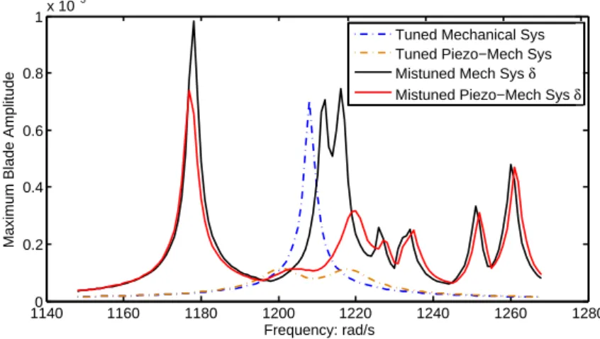
with respect to the mistuning-to-coupling ratio, it is shown in Fig.1.8that
vibra-tion amplitude magnificavibra-tion tends to exhibit a peak value when blade mistuning
1 1.2 1.4 1.6 1.8 0 0.02 0.04 0.06 0.08 Amplitude magnification
Standard deviation of random mistuning
Figure 1.8: Amplitude magnification as a function of mistuning strength. Calcu-lation is based on a lumped-parameter bladed disk model described in Chapter 3.
moderately weak interblade coupling is required for significant increases in forced-response amplitudes. Neither weak coupling nor extremely strong coupling could lead to spatial vibration localization and further amplitude magnification.
1.5.3
Mistuning sensitivity
With the identified mistuning sources and the basic understanding of the mis-tuning mechanism in the bladed disk, additional research issues to assess and improve the bladed disk design with respect to its sensitivity are presented. Blade-disk coupling
As just mentioned, the inter-sector coupling plays an important role in the sys-tem dynamics because it governs the communication of vibration energy among blades. Moreover, inter-sector coupling is largely dependent on the blade-disk interaction. This is deduced throgh an examination of the frequency/nodal
di-ameters diagram, as presented in Fig. 1.5.
In Section1.4.1, the relationship between the veering and the inter-blade
key information for the quantification of blade-disk coupling strength. Natu-rally, these quantitative coupling strength could be used for predicting mistuning sensitivity [15].
Blade-disk coupling can also be quantitatively measured through so-called
“coupling index” proposed by Javier and Mignolet [53]. The coupling index allows
to intuitively qualify the blade-disk coupling by observing the impact of blade stiffness drifts on the variation of blade-disk mode frequencies. Furthermore, an examination of blade-disk coupling also raises the possibility of influencing blade response by damping the disk. This concept will be discussed and calculated in Chapter 3.
Maximum forced response
A major concern in the academic community of mistuning is the prediction of maximum attainable forced response levels. The maximum amplification factor is traditionally defined as a ratio of the largest amplitude of mistuned bladed disk to the corresponding value of tuned response. Prediction of the maximum forced response increase due to mistuning has been one of the most challenging mistuning questions. A number of studies have attempted to provide a definitive answer.
The first research effort to address this issue was by Whitehead [54] who
concluded that the amplitude of blade response on a mistuned N-blade disk could
be as large as (1 +√N )/2. A single degree of freedom per blade model with a
negligible damping is used to obtain this upper limit to the amplification factor. This expression reveals that the number of blades is a major factor influencing the maximum forced response amplification.
Subsequent analyses [55–57] typically have supported and qualified the
oc-currence of such amplitude, and also extended the discussion to multi-degree of
freedom per blade models [58; 59] and further multi-stage assemblies [60]. The
maximum amplification factors were announced ranging from about 1.2 to 5.3 in these research efforts. On the other hand, these studies have also argued that the maximum amplification factor is affected by a range of possible factors, such as the mistuning strength, coupling level, attainable damping and the specificity of
operating conditions, etc. For this reason, the conflicting results tend to be case-dependent and difficult to generalize. A better understanding of the interaction of important factors affecting the maximum forced response is needed.
Mistuning pattern
It is well known that some particular pattern of the blade mistuning has a large effect on the forced response amplification, even for small mistuning. It is then natural to wonder what kind of mistuning patterns lead to high or low forced response and whether there exist common characteristics among these worst/best mistuning pattern.
Ewins [61] has first noted that by careful rearrangement of the same set of
non-identical blades on the disk, it is possible to reduce the maximum forced response levels. There have been several studies on using optimization methods to find the worst and best overall mistuning pattern in terms of forced response amplification
in recent decades [62; 63]. Petrov and Ewins [57] showed that the same set of 92
blades can be rearranged into a pattern, such that the maximum forced response could have a value less than 2 for the best arrangement and greater than 5 for the worst blade arrangement. If the industrial blades are detachable, this indicates a considerable potential for vibration reduction of mistuned bladed disks by simply rearranging the blade locations.
Mistuning identification
For mistuned bladed disk vibration research, how to identify the mistuning pat-tern existing in a manufactured bladed disk is also of engineering interest. For disks with detachable blades, the standard method consists of removing the indi-vidual blades for measurements of their natural frequencies. But problems arise when it comes to the integrally bladed disk structures (blisks), where the blades and disk form one integral piece and blades can not be removed from the as-sembly. Therefore, in order to accurately identify mistuning pattern in blisks, mistuning identification techniques based on experimental measurements of sys-tem response have been therefore developed recently to determine the individual blade mistuning pattern.


![Figure 2.1: A typical piezoelectric material with the top and bottom surfaces electrode and x 3 axis in the polarization direction [94]](https://thumb-eu.123doks.com/thumbv2/123doknet/14526719.723070/62.892.171.771.244.427/figure-typical-piezoelectric-material-surfaces-electrode-polarization-direction.webp)
![Figure 2.2: Different piezoelectric transduction modes [95]; P : polarization di- di-rection, ǫ: electric field.](https://thumb-eu.123doks.com/thumbv2/123doknet/14526719.723070/64.892.291.627.360.778/figure-different-piezoelectric-transduction-modes-polarization-rection-electric.webp)
![Figure 2.7: Synthetic inductances (gyrators) made of operational amplifiers: a) Riordan circuit; b) Antoniou circuit [95].](https://thumb-eu.123doks.com/thumbv2/123doknet/14526719.723070/76.892.208.732.705.945/figure-synthetic-inductances-gyrators-operational-amplifiers-riordan-antoniou.webp)
![Figure 3.3: a) Bladed-disk model with piezoelectric network; b) Base line bladed- bladed-disk model system with piezoelectric patches [125].](https://thumb-eu.123doks.com/thumbv2/123doknet/14526719.723070/85.892.187.730.264.478/figure-bladed-piezoelectric-network-bladed-bladed-piezoelectric-patches.webp)