HAL Id: tel-01866718
https://tel.archives-ouvertes.fr/tel-01866718
Submitted on 3 Sep 2018HAL is a multi-disciplinary open access archive for the deposit and dissemination of sci-entific research documents, whether they are pub-lished or not. The documents may come from teaching and research institutions in France or abroad, or from public or private research centers.
L’archive ouverte pluridisciplinaire HAL, est destinée au dépôt et à la diffusion de documents scientifiques de niveau recherche, publiés ou non, émanant des établissements d’enseignement et de recherche français ou étrangers, des laboratoires publics ou privés.
Control of multicellular power converters for microgrids
and renewable energies applications
Khaled Tamizi
To cite this version:
Khaled Tamizi. Control of multicellular power converters for microgrids and renewable energies appli-cations. Electric power. Université Paris Saclay (COmUE), 2018. English. �NNT : 2018SACLS212�. �tel-01866718�
Control of Multicellular Power
Converters for Microgrids and
Renewable Energies Applications
Thèse de doctorat de l'Université Paris-Saclaypréparée à Université Paris-Sud
École doctorale n°575 electrical, optical, bio : physics and engineering (EOBE) Spécialité de doctorat: génie électrique
Thèse présentée et soutenue à Gif sur Yvette, le 12 Juillet 2018, par
M Khaled TAMIZI
Composition du Jury : Eric MONMASSON
Professeur des Universités de Cergy Pontoise (SATIE) Président Guillaume GATEAU
Professeur, ENSEEIHT (- LAPLACE) Rapporteur
Mickaël HILAIRET
Professeur des Universités Franche-Comte (–FEMTO-ST) Rapporteur Cyrille GAUTIER
Doctor, site SAFRAN Paris-Saclay (SAFRAN TECH) Examinateur Eric LABOURE
Professeur des Universités Paris-Sud (– GeePs) Directeur de thèse Olivier BETHOUX
Professeur des Universités Sorbonne Université (– GeePs) Co-Directeur de thèse NNT = 20 18 S A C L S 212
I
Titre : Commande de convertisseurs multicellulaires destinés aux microgrids et aux systèmes d'énergies renouvelables
Mots clés : Electronique de puissance, commande, Energie renouvelable, Microgrids, MPC Résumé Les convertisseurs multicellulaires
DC-DC sont utilisés dans de nombreuses applications et de nombreux systèmes électriques. Ils présentent un intérêt particulier pour des applications spécifiques liées aux énergies renouvelables et aux Microgrids. Leur principal avantage provient de leur capacité intrinsèque à réduire les ondulations liées au découpage des grandeurs électriques en entrée et en sortie du système de conversion. Cette propriété intéressante au niveau système peut être étendue au fonctionnement interne du convertisseur en adjoignant à ce dernier un élément de filtrage par inductances couplées magnétiquement. Ce composant permet d’étendre les propriétés externes de
réduction des ondulations au
fonctionnement de chaque cellule du convertisseur. Il permet également d’augmenter la dynamique propre du système de conversion. Ces propriétés permettent de réduire significativement le niveau et le volume de filtrage en entrée et sortie du convertisseur et donc d’augmenter de manière importante sa compacité et son rendement énergétique. Cependant, l’ajout de ce dispositif magnétique induit, de par le couplage des équations du système qu’il provoque, une complexification du contrôle de la structure associée également à la nécessité d’augmenter le nombre de capteurs.
Ce travail de thèse a pour objectif d’établir et d’évaluer différents modes de contrôle pour les convertisseurs multicellulaires DC-DC. Le point commun aux méthodes proposées est de permettre la gestion aussi
bien des grandeurs externes au
convertisseur que des grandeurs internes constituées par les courants de circulation entre cellules connectées en parallèle. Ces composantes de courant sont également nommées « courants différentiels ». Trois types de contrôle sont étudiés : Pour le premier, des correcteurs linéaires classiques sont utilisés conjointement avec des techniques de découplage des équations du système. La robustesse de ces méthodes de contrôle vis-à-vis des incertitudes sur la connaissance des paramètres du système fait l’objet d’un focus particulier dans cette partie du travail. Pour le second, une version modifiée de la technique de commande connue sous le nom Model Predictive Control est proposée. Celle-ci permet d’assurer le contrôle de la fréquence de commutation et l’entrelacement des commandes PWM des cellules. Pour le troisième mode, nous étudions une méthode basée sur le contrôle vectoriel direct des courants différentiels.
Une implantation sur un système
numérique équipé d’un micro-processeur et d’un FPGA est proposée et permet de valider les résultats de l’étude théorique.
II
Title : Control of multicellular power converters for microgrids and renewable energies applications Keywords : Power Electronics, Control, Renewable Energy, Microgrids, MPC
Abstract : The interleaved multicell
DC-DC power converters are broadly used in many applications and systems especially
in renewable energy systems and
microgrids. They reduce the current ripple at the input and output side. Also, an implemented magnetic coupling between cells leads to reduce the current ripple in each of them and to improve the dynamical electrical behavior. These properties involve a reduction on the filtering requirements and so, allow to improve the converter compactness as well as its conversion efficiency. Nevertheless, for such power converters, the control complexity is also increased as well as the number of required sensors.
The thesis aims to establish different mode of control of interleaved multicell DC-DC converters. The common point of these
methods is to control the external quantities at the output of the converter but also the internal quantities, constituted by the circulating currents between parallel cells or in other words the differential currents. Three main strategies are investigated: the first one uses classical linear controllers with different decoupling technics and focuses on the robustness regarding the system parameters variations. The second one uses a Model Predictive Control technic which is designed to provide a fix switching frequency and interleaving of the cells PWM commands. The last one presents a space vector direct control of the differential currents.
In a last part, these control principles are tested on a prototype and implemented on a Microcontroller and FPGA board in order to carry out an experimental verification.
III
Table of Contents
Table of Contents ... III Table of Tables ... VII Table of Figures ... VIII Abbreviations ... XII
Description du contexte et travaux réalisés ... i
Les principaux résultats ... iii
Contrôle linéaire des convertisseurs multicellulaires entrelacés ... iii
Model Predictive Control des convertisseurs multicellulaires... iv
Contrôle vectoriel et Model Predictive Control des convertisseurs multicellulaires ... v
Résultats expérimentaux ... vi
Chapter 1. Introduction ... 1
Chapter 2. State of Art ... 3
2.1. Introduction ... 3
2.2. Multicell Power Converter ... 3
2.2.1. Topologies of Multilevel DC/DC Converters ... 3
2.2.2. Multicell Power Converter in Solar application and microgrids ... 6
2.3. Classical control and LQR ... 7
2.3.1. Hysteresis control ... 8
2.3.2. Linear control using PWM ... 9
2.3.3. PI/IP control ... 9
2.3.4. State space control ... 10
2.4. Model Predictive Control ... 11
2.4.1. Basic principles of Model Predictive Control ... 12
2.4.2. Finite control set MPC ... 13
2.5. Space vector Placement ... 17
Chapter 3. Classical control of multicell interleaved power converter ... 19
3.1. Introduction ... 19
3.2. Multi-cell interleaved buck converter and its control-oriented model ... 20
3.2.1. Multi-cell interleaved buck converter for solar application ... 20
IV
3.2.3. Mode analysis of the state-space average model. ... 24
3.2.4. Simulink model of multicell interleaved DC-DC buck converter ... 25
3.2.5. Simulation specifications ... 27
3.3. Proportional-Integral Controller ... 28
3.4. State Feedback ... 29
3.4.1. Control structure and the related extended model ... 29
3.4.2 . Tuning of state feedback gain ... 31
3.4.3. Simulation results ... 33
3.5. Decoupling strategy ... 37
3.5.1. Control structure degrees of freedom... 37
3.5.2. Simulation results ... 39
3.6. Linear quadratic regulator (LQR) ... 43
3.6.1. Objective function ... 43
3.6.2. State feedback design by using LQR ... 44
3.7. Conclusion (Comparison) ... 48
Chapter 4. Model Predictive Control ... 49
4.1 . Introduction ... 49
4.2. Finite control set MPC ... 50
4.3. FCS-MPC with fixed switching frequency ... 53
4.3.1 . PWM with sawtooth carriers ... 53
4.3.2. Fixed switching frequency algorithm for FCS-MPC ... 54
4.4. Model Predictive Control for multicell Buck Converter ... 58
4.4.1. Mathematical model of a 3-cells Buck converter ... 58
4.4.2. Current Control of multicell Buck converter ... 59
4.4.3. Voltage Control of multicell Buck converter ... 68
4.5. Model Predictive Control for multicell Boost converter ... 70
4.5.1. Mathematical Modeling of multicell boost converter ... 71
4.5.2. Current Control of multicell Boost converter ... 74
4.5.3. Voltage Control of Boost converter ... 80
4.6. Conclusion ... 81
Chapter 5. Space vector placement based on model Predictive Control ... 83
5.1. Introduction ... 83
V
5.3. Physical impact of common and differential modes of the currents on output coupled inductors 86
5.4. Control of the three current modes ... 87
5.4.1. Control of the three voltage modes ... 88
5.4.2. Determination of the duty-cycles ... 90
5.4.3. Direct control of differential currents ... 91
5.4.4. Choice of the space vector sequence... 97
5.4.5. Impact of the choice of a sequence ... 99
5.4.6. Levels transitions ... 103
5.4.7. Control point of view of the proposed strategy... 104
5.4.8. Simulation ... 105
5.5. MPC with space vector placement... 107
5.5.1. Main controller... 107
5.5.2. Secondary controller ... 108
5.5.3. Simulation ... 110
5.6. Conclusion ... 112
Chapter 6. Experimental Results ... 114
6.1. Introduction ... 114
6.2. Experimental test bench ... 115
6.2.1. Power supply ... 116
6.2.2. The inductance elements ... 116
6.2.3. The converter ... 117
6.2.4. Measurements sensors ... 117
6.2.5. Hardware for implementation of the controller ... 118
6.3. Implementation of classical controller ... 119
6.3.1. Controller implementation ... 120 6.3.2. Current controllers ... 120 6.3.3. Voltage controller ... 123 6.3.4. Controllers implementation ... 124 6.3.5. Experimental results ... 128 6.4. Implementation of FCS-MPC ... 131
6.4.1. Synthesis of the controller ... 131
VI
6.4.3. Controller implementation ... 133
6.5. Conclusion ... 137
Chapter 7. Conclusion ... 138
VII
Table of Tables
Table 2-1 The values of QP cost function ... 16
Table 3-1 Multi-Cell coupled power converter parameters ... 22
Table 3-2 Closed loop system specification ... 27
Table 3-3 coefficients of the equivalent full state feedback ... 36
Table 3-4 coefficients of the equivalent full state feedback ... 42
Table 3-5 LQR design of the full state feedback strategy setting parameters ... 44
Table 4-1: Switching vectors satisfying the sawtooth carriers behavior ... 56
Table 2 Simulation parameters for the 3-cell buck converter ... 61
Table 3 Switching vector for multicell boost converter ... 73
Table 4 Simulation parameters for boost converter ... 75
Table 5-1 Parameters used for the 3-Cell buck converter ... 84
Table 5-2 Switch combinations for a multi-cell power converter: cell-voltages and cell-states ... 85
Table 5-3 Switch combinations for a multi-cell power converter: fictitious voltage ... 88
Table 5-4 Switch combinations for a multi-cell power converter: dimensionless output voltage ... 89
Table 5-5 Valid sequences for level 0 to 1 ... 98
Table 5-6 Valid sequences for level 1 to 2 ... 99
VIII
Table of Figures
Figure 2-1 Multicell Power converter: series connection with isolated power supply ... 4
Figure 2-2 Different topology of flying capacitor converters ... 4
Figure 2-3 Parallel multicell converter with star-connected inductors ... 5
Figure 2-4 InterCell Transformers. a) cyclic cascade configuration b) monolithic configuration ... 6
Figure 2-5 phase currents of three cells parallel multicell converter: a) uncoupled b)coupled[6] ... 6
Figure 2-6 schematic diagram of DC microgrid structure ... 7
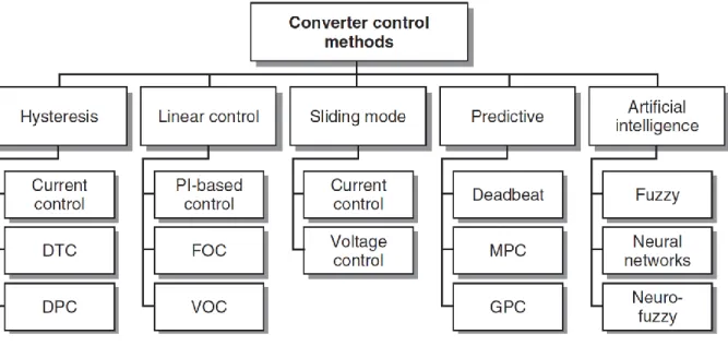
Figure 2-7 Different types of converter control for power converters and drives ... 8
Figure 2-8 Hysteresis current control for a single-phase inverter. (a) Control scheme. (b) Load current .... 9
Figure 2-9 Diagram of the decoupled PQ Control ... 10
Figure 2-10 Bloc diagram of the decoupled control strategy of a multicell power converter ... 10
Figure 2-11 current sharing and voltage regulation for n-arm buck converter ... 11
Figure 2-12 MPC principle ... 12
Figure 2-13 Model predictive control :a) with continuous control set, b)with finite control set ... 14
Figure 2-14 Block diagram of model predictive control of the currents of a 3-Cell buck converter ... 15
Figure 2-15 Current response :a)currents in the 3 cells , b) zoom and predicted currents ... 16
Figure 2-16 block diagram of DPC with VF control and choke inductance estimators for three phase ac/dc voltage source converters(VSCs) ... 17
Figure 2-17 Example response of (a) derivatives of active and reactive powers, and (b) cost function and their components. ... 18
Figure 3-1 Multi-Cell coupled power converter architecture ... 21
Figure 3-2 The equivalent average model of Multi-cell interleaved buck converter ... 23
Figure 3-3 The Simulink model of a multicell interleaved DC-DC buck converter (a) The buck converter model with three half-bridges in parallel (b) One half bridge model using two IGBTs (c)The implemented equivalent average model of a half-bridge ... 26
Figure 3-4 Open loop simulation of multicell interleaved DC-DC converter : (a) Switched model (b)Average model ... 27
Figure 3-5 PI controller with system dynamics of multicell interleaved Buck DC-DC converter... 28
Figure 3-6 PI and IP simulation result : (a)The same current command , (b)Coupling effect ... 29
Figure 3-7 Extended system with full state feedback... 30
Figure 3-8 closed loop behavior using state feedback criteria: common mode response ... 34
Figure 3-9 closed loop behavior using state feedback criteria: differential mode response ... 34
Figure 3-10 . closed loop behavior using state feedback criteria: a single current step response (a)small signal (b) large signal ... 35
Figure 3-11 . closed loop behavior using state feedback criteria: ICT parameters l and m change(a) 𝑙 = 19.8𝑚𝐻 and 𝑚 = 9.7𝑚𝐻 (b) 𝑙 = 19.7𝑚𝐻 and 𝑚 = 9.8𝑚𝐻. ... 36
Figure 3-12 Control structure of the decoupling strategy ... 38
Figure 3-13 closed loop behavior using decoupling criteria: common mode response ... 39
Figure 3-14 closed loop behavior using decoupling criteria: differential mode response ... 40
Figure 3-15 . closed loop behavior using decoupling criteria: a single current step response (a)small signal (b) large signal ... 41
IX
Figure 3-16 . Closed loop behavior using decoupling criteria: ICT parameters l and m change(a) 𝑙 =
19.8𝑚𝐻 and 𝑚 = 9.7𝑚𝐻 (b) 𝑙 = 19.7𝑚𝐻 and 𝑚 = 9.8𝑚𝐻. ... 42
Figure 3-17 . Closed loop behavior using LQR design:(a) Common mode and (b)Differential mode response. ... 45
Figure 3-18 . Closed loop behavior using LQR design a single current step response :(a) Small signal (b) Large signal. ... 46
Figure 3-19 . Closed loop behavior using LQR design ICT parameters change (𝑙 = 19.7𝑚𝐻 and = 9.8𝑚𝐻 ):(a) Small signal (b) Large signal. ... 47
Figure 4-1 Classification of predictive control methods used in power electronics ... 49
Figure 4-2 Flowchart of MPC algorithm ... 52
Figure 4-3 PWM with Sawtooth carrier ... 53
Figure 4-4 Three sawtooth carriers –two periods ... 54
Figure 4-5 Flowchart for fixing the switching frequency ... 55
Figure 4-6 Illustration of possible sequences for 3 cells and one line (S) change per switching period... 57
Figure 4-7 Illustration of possible sequences for 3 cells and 3 line (S) changes per switching period ... 57
Figure 4-8 Block diagram of model predictive current control for interleaved multicell buck converter ... 59
Figure 4-9 Flowchart of MPC :current control of multicell interleaved Buck DC-DC converter ... 60
Figure 4-10 Simulation result of Buck converter-MPC-Current response: common mode uncoupled system ... 62
Figure 4-11 Command applied to each cell in steady state ... 63
Figure 4-12 Current in Cell1 for a magnetically uncoupled system :(a) Time domain (b) Frequency domain ... 63
Figure 4-13 Simulation results: Buck converter-MPC-Current response for common mode ... 64
Figure 4-14 Command applied to each cell in steady state ... 65
Figure 4-15 Simulation results: Buck converter-MPC-Current response for differential mode ... 65
Figure 4-16 Simulation results: Buck converter-MPC-Current response in case of single current step ... 66
Figure 4-17 Simulation results: Buck converter-MPC-Current response with current saturation in common mode ... 66
Figure 4-18 Simulation results: Buck converter-MPC-Current response ; Sensitivity to load variations.... 67
Figure 4-19 Simulation result: Buck converter-MPC-Current response; Sensitivity to change in the self-inductance and mutual self-inductance ... 68
Figure 4-20 Simulink model of FCS-MPC –Voltage control ... 70
Figure 4-21 Simulation result: Control of the buck converter output voltage (a)Outputs response (b) Current response ... 70
Figure 4-22 Interleaved Multicell Boost converter in parallel connection ... 71
Figure 4-23 Equivalent average model of the interleaved multicell DC-DC boost converter ... 71
Figure 4-24 Block diagram of model predictive control applied to an interleaved multicell boost converter ... 74
Figure 4-25 Simulation result: Boost converter-MPC-Current response for common mode ... 76
Figure 4-26 Simulation result of Boost converter-MPC-Current response: differential mode ... 76
Figure 4-27 Simulation result of Boost converter-MPC-Current response: single current step mode ... 77
Figure 4-28 Simulation result: Boost converter-MPC-Current response; Current saturation in common mode ... 77
X
Figure 4-29 Simulation result of Boost converter-MPC-Current response: sensitivity to the change in the
load ... 78
Figure 4-30 Simulation result: Boost converter-MPC-Current response; sensitivity to the magnetic filtering device parameters ... 79
Figure 4-31 Impact of the magnetic filtering device parameters ... 79
Figure 4-32 Simulink model of boost converter-Two loops Voltage Control ... 81
Figure 4-33 Simulation of the controlling output voltage of boost converter (a)Outputs response (b) Current response ... 81
Figure 5-1 3-Cell parallel Buck converter ... 84
Figure 5-2 Cyclic cascade coupling inductor topology ... 86
Figure 5-3 reluctance model of the multicell interleaved power converter ... 86
Figure 5-4 An example of sequence and the corresponding dimensionless voltage modes ... 89
Figure 5-5 Direct control of differential currents in one switching period ... 95
Figure 5-6 Flowchart of the proposed method for the direct control of differential currents ... 97
Figure 5-7 Figure helping to select a proper sequence ... 98
Figure 5-8 Impact of sequences on the average differential currents when 𝑣𝑐𝑚 ∗ 𝑘 ∈ [0,1] ... 100
Figure 5-9 Impact of sequences on the average differential currents when 𝑣𝑐𝑚 ∗ 𝑘 ∈ [1,2] ... 101
Figure 5-10 Impact of sequences on the average differential currents when 𝑣𝑐𝑚 ∗ 𝑘 ∈ [2,3] ... 102
Figure 5-11 The average differential currents when of sequences 5,6,1 and 𝑣𝑐𝑚 ∗ 𝑘 ∈ [0,3] ... 103
Figure 5-12 The block diagram of controlling differential currents ... 104
Figure 5-13 The 𝑧 model of the control system ... 104
Figure 5-14 Simulation results for 𝑣𝑐𝑚 ∗ steps within one level interval:(a) when 𝑣𝑐𝑚 ∗∈ [0,1] (b) when 𝑣𝑐𝑚 ∗∈ [1,2] (c) when 𝑣𝑐𝑚 ∗∈ [2,3] (d) moving average of differential currents ... 105
Figure 5-15 Simulation results for 𝑣𝑐𝑚 ∗ steps variation from one level interval to another: (a) when 𝑣𝑐𝑚 ∗∈ [0,1] ↔ 𝑣𝑐𝑚 ∗∈ [1,2], (b) when 𝑣𝑐𝑚 ∗∈ [1,2] ↔ 𝑣𝑐𝑚 ∗∈ [2,3] (c) when 𝑣𝑐𝑚 ∗∈ [0,1] ↔ 𝑣𝑐𝑚 ∗∈ [2,3] (d) moving average of differential currents ... 106
Figure 5-16 Block diagram of the whole control system ... 107
Figure 5-17 Flowchart of the secondary controller(MPC with space vector placement) ... 109
Figure 5-18 Simulation results of the 3-Cell Buck converter controlled with the proposed MPC-Space vector placement ... 110
Figure 5-19 Simulation result of 3-Cell Buck converter using MPC- Space vector placement: sensitivity to load change,(a)three mode currents (b)moving average of the differential currents ... 111
Figure 5-20 Simulation result of 3-Cell Buck converter using MPC- Space vector placement: sensitivity to inductance change,(a)three mode currents (b)moving average differential currents ... 112
Figure 6-1 Block diagram of the test bench ... 115
Figure 6-2 Configuration of electrical machine inductance (a) the stator winding (b) the connection configuration ... 116
Figure 6-3 The structure of power converter for test bench ... 117
Figure 6-4 The hall effect current sensors ... 118
Figure 6-5 Block diagram of the DS1202 card ... 118
Figure 6-6 Block diagram of the DS1302 card ... 119
Figure 6-7 The block diagram of buck converter control structure ... 120
Figure 6-8 Block diagram of the currents control: decoupling strategy ... 122
XI
Figure 6-10 Simulink implementation of voltage controller: PI controller ... 124
Figure 6-11 Implementation of the external data acquisition with XSG blocks ... 125
Figure 6-12 Implementation of the IIR filter with XSG blocks... 125
Figure 6-13 Synchronization and averaging of data acquisitions with XSG blocks ... 126
Figure 6-14 Implementation of PI and IP controllers with anti-windup with XSG blocks ... 127
Figure 6-15 Implementation of the decoupling strategy with XSG blocks(a) current transformation (b) duty cycles transformation ... 127
Figure 6-16 Programing the LQR strategy by XSG blocks ... 128
Figure 6-17 experimental results for PI controllers: (a) for the same current references , (b) in case of differential solicitations ... 128
Figure 6-18 experimental result of closed loop behavior using the decoupling strategy: a) common mode response b) differential mode response c) single current step response ... 129
Figure 6-19 . Experimental result of closed loop behavior using LQR design: a) Common mode b)Differential mode response. ... 130
Figure 6-20 . Experimental result of closed loop behavior using LQR design a single current step response :(a) Small signal (b) Large signal. ... 130
Figure 6-21 Block diagram for implementation of FCS-MPC on FPGA ... 131
Figure 6-22 Block diagram for the FPGA program of FCS-MPC ... 133
Figure 6-23 Implementation of the predicted currents with XSG blocks ... 134
Figure 6-24 Programing the average currents calculations by XSG blocks ... 135
Figure 6-25 Implementation of the cost function calculations with XSG blocks ... 135
Figure 6-26 Programing the constraints by XSG blocks ... 136
XII
Abbreviations
µC Microcontrollers
AC Alternating Current
ADC Analog to Digital Converters
ASIC Applied-Specific Integrated Circuit
A-W Anti-Windup
CC-MPC Continuous Control - Model Predictive Control
CT Conversion Ratio
DC Direct Current
DPC direct power control
DSP Digital Signal Processor
DTC Direct Torque Control
FCS-MPC Finite Control Set -Model Predictive Control
FFT Fast Fourier Transform
FPGA Field-Programmable Gate Array
I/O Input/Output
ICTs Inter Cell Transformers
IGBT Insulated-Gate Bipolar Transistor
IIR Infinite Impulse Response
LP Linear Programing
LQR Linear Quadratic Regulator
MIMO Multi Inputs Multi Outputs
MPC Model Predictive Control
MPP Maximum Power Point
Op-Amp Operational Amplifiers
P Active Power
PI proportional–integral
PV Photovoltaic
PWM Pulse Width Modulation
Q Reactive Power
QP Quadratic Programing
RAM Random Access Memory
RMS Root Mean Square
seg Time segment
SISO Single Input Single Output
SVD Space Vector Direct Control
SVM Space Vector Modulation
SVP space vector placement
VF Virtual Flux
VOC Voltage Oriented Control
VSC Voltage Source Converters
i
Résumé
Description du contexte et travaux réalisés
Les convertisseurs DC-DC multicellulaires entrelacés sont d'excellents candidats pour les microgrids et les systèmes de production électrique à base de renouvelable en raison de leur comportement électrique et de leur possible dynamique élevée. En effet, l'une des principales caractéristiques de ces convertisseurs est de réduire les ondulations des grandeurs électriques à leur entrée et à leur sortie. Ils constituent donc une bonne option pour les convertisseurs destinés aux applications solaires en raison de la réduction des contraintes électriques sur la chaine de conversion photovoltaïque tout en réduisant les exigences de filtrage et donc la taille des filtres entrainant, de ce fait, une augmentation de la compacité du convertisseur. De plus, la nature multicellulaire de cette famille de convertisseurs offre la possibilité d'obtenir un rendement énergétique très élevé sur une très large plage de puissance en permettant de choisir le nombre de cellules à mettre en service. Là encore, ceci constitue un avantage indiscutable pour les applications de conversion pour les systèmes de production électrique à base de renouvelable par essence de nature très fluctuante.
Ces avantages sont contrebalancés par la difficulté de contrôle due à l'augmentation significative du nombre de grandeurs à contrôler. Le couplage magnétique entre cellules qui conduit à une amélioration supplémentaire des performances du système ajoute à cette complexité en introduisant des relations croisées entre les commandes de chacune des cellules et les grandeurs à contrôler.
Le travail présenté dans ce document porte sur le contrôle de telles structures. Nous présentons trois approches différentes pour contrôler les convertisseurs DC-DC multicellulaires entrelacés couplés. La première utilise des contrôleurs linéaires appliqués à une représentation modale du système. Un modèle de contrôle prédictif (MPC) est utilisé dans la seconde et une approche basée sur un contrôle vectoriel direct avec prédiction de modèle est utilisée pour la troisième.
Il existe plusieurs publications sur le contrôle des convertisseurs de puissance multicellulaires. Dans [1-6] les auteurs proposent des solutions basées sur le contrôle linéaire, certaines d'entre eux travaillent sur des contrôleurs PI indépendants et les autres sur le contrôle d'état. Dans [7-9], des techniques du type MPC (Model Predictive Control) sont utilisées mais dans les implémentations proposées, la fréquence de commutation est variable. Ce problème est traité dans [10-16], où les auteurs proposent des méthodes pour limiter les variations ou pour régler la fréquence de commutation. Dans [17-27], les méthodes de contrôle direct de la puissance et de placement vectoriel des commandes sont étudiées. Nous pouvons noter que la plupart de ces travaux ont été réalisés sur des convertisseurs AC ou AC multicellulaires, mais le problème des convertisseurs DC-DC multicellulaires entrelacés couplés n'a pas été traité de manière significative.
L'objectif principal de cette thèse est de concevoir le système de contrôle dédié à de tels convertisseurs. Les stratégies de contrôle proposées devraient permettre d'équilibrer et
ii
de stabiliser les convertisseurs de puissance multicellulaires entrelacés couplés et de surmonter les effets de couplage. Le fort couplage magnétique entre les cellules du convertisseur rend en effet l'équilibrage du courant difficile et augmente la complexité du contrôle. Quels sont les effets du couplage sur l'équilibrage ? Quelle est l'influence des variations des paramètres du convertisseur sur la stabilité ? Quelles sont les limites de mise en œuvre du contrôleur en temps réel ?
Nous tentons dans ce document de répondre à ces questions. Nous nous concentrons pour cela sur l'équilibrage des courants dans les cellules, sur la stabilité et sur la robustesse du contrôleur vis-à-vis des variations de la charge ou des paramètres du convertisseur. La mise en œuvre en temps réel est également un axe important de ce travail.
Ce document est constitué de six chapitres :
- En introduction, nous avons formulé le problème, la portée, les motivations et les objectifs de ce travail.
- Le deuxième chapitre donne un bref état des lieux des différents sujets abordés dans la thèse.
- Le troisième chapitre présente une première approche basée sur la commande linéaire des convertisseurs de puissance multicellulaires entrelacés couplés. Ce chapitre couvre la modélisation mathématique du convertisseur de puissance et présente différentes stratégies de contrôleurs linéaires et une analyse de chacune d'entre elles. Les méthodes de contrôle présentées sont successivement basées sur des contrôleurs PI appliqués avec une stratégie de découplage modale, sur un retour d'état découplant et un retour d’état réglé sur un critère quadratique (LQR : linear quadratic regulator).
- Le chapitre quatre présente une méthode basée sur le principe du contrôle prédictif du convertisseur par la méthode FCS-MPC (Finite Control Set Model Predictive Control). La méthode proposée est une évolution des méthodes utilisant ce principe de contrôle. Elle est conçue de telle manière à permettre de fixer la fréquence de découpage et à assurer un séquencement des commandes imitant l’entrelacement des commandes des cellules générées par les modulateurs à porteuses triangulaires généralement utilisés pour cette famille de convertisseurs. La conception et les performances d’un tel contrôleur sont analysées dans le cas de deux structures de type Boost et Buck et la robustesse du contrôleur est analysée vis-à-vis d’une modification de certains paramètres du système.
- Le chapitre cinq présente une stratégie de contrôle vectoriel des commandes des cellules (Space Vector Control) combinée à une stratégie MPC (Model Predictive Control). Les performances de la combinaison des deux méthodes de contrôle sont analysées et validées par simulation.
- Le dernier chapitre concerne la mise en œuvre expérimentale de différents contrôleurs proposés aux chapitres trois et quatre. Ce chapitre est divisé en trois parties. La première partie décrit le banc d'essai expérimental et ses composants. La deuxième partie traite de la mise en œuvre du contrôle linéaire et présente les résultats expérimentaux. La dernière partie est consacrée à la mise en œuvre de la méthode FCS-MPC et montre la stratégie d’implantation dans une cible FPGA et les difficultés de mise en œuvre.
iii
Les principaux résultats
Contrôle linéaire des convertisseurs multicellulaires entrelacés
La structure servant de support à cette partie est un convertisseur multicellulaire à 3 cellules de type Buck dont le filtre de sortie est constitué par une inductance couplée.
Le modèle moyen (à l’échelle de la fréquence de découpage) permet de construire le modèle d’état du convertisseur. Cette modélisation orientée contrôle montre qu’il existe un couplage significatif entre les différentes cellules.
𝑑 𝑑𝑡[ 𝑖1 𝑖2 𝑖3 ] = − [ 𝑙 −𝑚 −𝑚 −𝑚 𝑙 −𝑚 −𝑚 −𝑚 𝑙 ] −1 [ 𝑟 0 0 0 𝑟 0 0 0 𝑟 ] [ 𝑖1 𝑖2 𝑖3 ] + [ 𝑙 −𝑚 −𝑚 −𝑚 𝑙 −𝑚 −𝑚 −𝑚 𝑙 ] −1 ([ 𝑑1 𝑑2 𝑑3 ] 𝑣𝑖 − [ 1 1 1 ] 𝑒𝑙)
Dans ce premier chapitre, on aborde la manière la plus simple et la plus robuste de mettre en œuvre un schéma de contrôleur dédié au contrôle des courants dans cette famille de convertisseur.
Pour faire face à ce problème, différentes approches sont évaluées.
- La première est basé sur un contrôle des courants dans chaque cellule par des contrôleurs indépendants classiques de type PI. Ce type de contrôleur est facile à mettre en œuvre et un anti-windup est facile à utiliser dans cette stratégie. Ce contrôleur donne de bons
PV array 3-Cell DC-DC converter
Filter : Coupled inductors
LOAD : - Batteries Charger - DC-AC inverter - …. PWM Filter + -controller MPP tracker
iv
résultats lorsque les courants dans les cellules ont des variations identiques, mais lorsqu'il y a variation individuelle des courants ou déséquilibre dans le convertisseur, il est démontré que ce type de contrôleur ne peut pas gérer correctement l’influence des voies les unes sur les autres.
- La seconde est basée sur une méthode modale. Elle est aisée à comprendre et à synthétiser d’un point de vue technique. Il est démontré qu’en fonctionnement en mode linéaire, cette méthode permet un très bon découplage entre les entrées de référence et les sorties associées. Cependant, un système anti-windup efficace ne peut pas être mis en œuvre pour prendre en compte de façon optimale la saturation des intégrateurs dans cette stratégie. Une stratégie équivalente sur le papier utilise une stratégie de contrôle d’état découplante, ce qui signifie que les coefficients du contrôleur sont définis de manière à assurer un découplage de la structure de commande. Les simulations montrent que le couplage est plus faible que dans le cas du contrôle modal et moins agressif en ce qui concerne les variations du rapport cyclique. Il est également montré que le comportement du système en boucle fermée est sensible aux paramètres magnétiques du coupleur. Or, ces derniers peuvent être difficiles à évaluer avec précision. Notons également que le contrôle des modes différentiels de cette structure met en œuvre des gains élevés pour compenser la dynamique naturellement lente associée à ces modes, ce qui peut entraîner une sensibilité au bruit et un risque de saturation des rapports cycliques.
- La dernière méthodologie est basée sur un retour d'état complet d'un modèle étendu dont les paramètres sont définis en minimisant une fonction de coût quadratique. Cette technique dite LQR permet de trouver un bon compromis entre les différents points clés du comportement du contrôleur, à savoir la stabilité, le temps de réponse, le découplage et la robustesse. Il est démontré que les réglages obtenus, maintiennent un couplage qui reste toutefois faible et acceptable. De plus ce contrôleur présente une structure quasi découplée du point de vue des intégrateurs permettant de mettre en œuvre aisément une technique anti-windup simple et efficace. De plus, le contrôleur actionne moins les rapports cycliques pendant les phases transitoires, ce qui réduit la sensibilité au bruit. Enfin, avec de tels réglages, ce contrôleur est également plus robuste aux changements de paramètres magnétiques des coupleurs, ce qui constitue un atout important.
En conclusion de ce chapitre, l'approche par retour d'état complet basée sur la méthode LQR présente un compromis très intéressant vis-à-vis des différentes exigences issues d’un cahier des charges. De plus ce type de contrôleur peut être aisément implanté dans un microcontrôleur ou un FPGA. Ces résultats très positifs encouragent à valider l'étude sur un banc d'essai de laboratoire. Ce qui sera fait dans le dernier chapitre.
Model Predictive Control des convertisseurs multicellulaires
Le principe est ici d’utiliser un algorithme basé sur le modèle de fonctionnement du convertisseur pour définir au sens d’un critère la séquence de commandes optimale des interrupteurs d’une structure multicellulaire à l’échelle d’une période de découpage. À la différence d’autre méthodes issues de la littérature la technique de commande proposée
v
permet de maitriser la fréquence de découpage tout en assurant un séquencement des commandes imitant l’entrelacement des commandes des cellules générées par les modulateurs à porteuses triangulaires entrelacées.
Il est démontré dans ce chapitre que la méthode de contrôle FCS-MPC peut être utilisée pour contrôler un convertisseur DC-DC multicellulaire couplé magnétiquement. Il offre la possibilité d'équilibrer le courant et de contrôler le courant global d'un tel convertisseur même s'il existe un fort couplage entre les cellules. La méthode proposée permettant de fixer la fréquence de commutation des interrupteurs est validée. Les avantages de la méthode proposée au-delà de la fréquence fixe sont les suivants :
- Une réduction du nombre de séquences à évaluer permettant une implémentation en temps réel avec une cible FPGA. De plus cette méthode ne nécessite pas de calcul hors ligne ;
- Une fréquence d’échantillonnage des grandeurs à contrôler faible (les mesures sont effectuées au début de la période de découpage) ;
- Une mise en œuvre possible pour un nombre élevé de cellules ou pour les convertisseurs multiniveaux.
Toutefois, le contrôle basé sur la méthode FCS-MPC a aussi beaucoup de limites : - Le nombre de séquences à évaluer par période de découpage devient très vite très
important. Ce nombre dépend en effet du nombre de points qui divise la période de de découpage définissant par ailleurs la résolution en rapport cyclique ;
- Un système numérique très rapide est donc nécessaire pour tester en temps réel toutes les séquences de commutation possibles et trouver la solution optimale ;
- Ce type de contrôleur est sensible aux paramètres du modèle. Il peut donc être nécessaire d’ajouter certaines fonctions pour compenser certaines déviations, comme par exemple des observateurs pour estimer certains paramètres.
En conclusion, en raison de ces limitations, la méthode FCS-MPC n'est pas vraiment satisfaisante. Pour lever ces limitations, une nouvelle méthodologie basée également sur le modèle du convertisseur mais avec beaucoup moins de limitations est proposée au chapitre suivant.
Contrôle vectoriel et Model Predictive Control des convertisseurs
multicellulaires
La méthode mixte associant le contrôle vectoriel aux principes du MPC est une réelle amélioration par rapport au FCS-MPC présenté au chapitre précédent.
En effet, la connaissance du modèle permet de calculer directement la durée d'application des vecteurs d'une séquence de vecteurs prédéfinie avec une résolution possible élevée sans avoir à tester différentes possibilités de rapport cycliques. Ainsi, la limitation précédente disparaît. Cette méthode assure également une fréquence de commutation constante et permet, par le choix des séquences réalisées, d’assurer un entrelacement régulier des cellules en régime permanent. La méthode MPC appliquée ici
vi
vise à déterminer la meilleure séquence à appliquer au convertisseur de puissance. Ceci conduit à évaluer une fonction coût pour seulement 12 séquences différentes par rapport à la méthode FCS-MPC précédente qui nécessitait 1000 évaluations pour seulement 9 points de prédiction sur la période de découpage. Cette méthode donne donc clairement de bien meilleurs résultats pour un coût d’implantation plus bas.
Dans la dernière partie de ce chapitre, la robustesse de la méthode est analysée par rapport aux erreurs dans la connaissance des paramètres du modèle. Les simulations montrent que le convertisseur reste stable même pour des erreurs de modèle significatives. Néanmoins, l'erreur du modèle sur l'inductance provoque un décalage significatif de la valeur moyenne du courant différentiel qui peut conduire à la saturation du composant magnétique. Cette sensibilité à l'inductance nécessite plus d'investigation afin d’être géré.
D'autres améliorations peuvent également être apportées en ce qui concerne la gestion des saturations des rapports cycliques. Ce type de problème survient surtout lorsque le mode commun moyen est proche du niveau 0 ou niveau 3 car certains rapports cycliques sont alors très petits ou très importants. Mais ce problème peut également survenir en cas de variation importante et rapide de la tension de mode commun.
Résultats expérimentaux
La structure générale du banc d'essai est présentée ci-dessous.
Ce banc d'essai est construit autour d'un convertisseur de puissance à trois cellules et d’une inductance couplée en sortie. On peut également voir sur cette figure, que le contrôleur utilise une implémentation mixte : la gestion des courants et l’élaboration des PWM sont implantées dans un FPGA (Xilinx® Kintex® -7 XC7K325T FPGA) et le contrôleur de tension de sortie est intégré dans un microcontrôleur (Freescale QorlQ P5020, double cœur, cache de données L1 de 2 GHz 32 Ko par cœur, 32 Ko de cache d'instructions L1 par cœur, 512 Ko de cache L2 par cœur, 2 Mo de cache L3 total, Freescale QorlQ P1011 800 MHz pour la communication avec le PC hôte). Tous ces périphériques sont inclus dans une MicroLabbox Dspace. La dernière partie correspond à la partie le logicielle implantée sous Controldesk (fonctionnant sur un PC) dédiée au contrôle du banc d'essai et fournissant des moyens de surveillance.
Dans ce chapitre, nous décrivons la mise en œuvre des stratégies de contrôle développées précédemment. Nous avons vu que les résultats expérimentaux obtenus sur le banc d'essai valident les résultats théoriques et les analyses des chapitres précédents pour le contrôleur PI indépendant, la stratégie de contrôle par découplage et le retour d'état réglé par la technique LQR. Toutes ces méthodes de contrôle ont été facilement implémentées sur la cible FPGA. En ce qui concerne la méthode de contrôle FCS-MPC, l’implantation sur FPGA n’a pas abouti même si nous avons proposé dans ce travail des descriptions partielles de sa mise en œuvre. Au moment de la rédaction du document, il n'y a pas de résultats expérimentaux pour cette méthode en raison de la difficulté à implanter la totalité de l’algorithme dans la cible FPGA.
vii DC-DC inverter Filter LOAD : - Batteries Charger - DC-AC inverter - …. 𝑖1 PV array 𝑘
Micro controller FPGA
* Setting parameters. * Controllers gains. * Read measurements. * Read controller outputs (duty cycle).
* Controller type * Voltage control or Current control.
dSPACE Control desk PC
PI PI
−𝑘
𝑘
Current control loop Voltage control loop
ADC ADC
IIR filter IIR filter
1
Chapter 1. Introduction
Interleaved multicell DC-DC converters are excellent candidates for microgrids and renewable energy systems due to their electrical behavior and their possible high dynamics. Indeed, one of the main characteristics of these converters is to improve the current ripples at their input and output. They are thus a good option for solar system due to the reduction of the electrical stress on the PV string while reducing the filtering requirements and thus the size of the filters and thereby leading to an increase of the converter compactness. Moreover, the multicellular nature of this family of converters offer the possibility of obtaining a very high energy efficiency over a very wide range of power by allowing to choose the number of cells to put into operation. Again, this is an indisputable advantage for conversion applications for renewable energy systems.
These advantages are counterbalanced by the control difficulty due the to the significant increase in the number of variables to be controlled in this type of complex system. The coupling between cells which leads to further improve of the performances of the system adds to this complexity. The work presented in this paper deals with the control of such structures.
The scope of this research is based on three different approaches to control coupled interleaved multicell DC-DC converters, the first one is based on linear control applied to a modal representation of the system, model predictive control (MPC) is used for the second and space vector direct control (SVD) with model prediction for the third.
There are several publications on the subject of multicell power converters control. In [1]–[4] authors propose solutions based on linear control, some of them are working on independent PI controllers and the others are working on state space control. In [5], [6] MPC is used but, in the proposed control implementations, the switching frequency is variable. In [7]–[13] authors propose methods to limit the variations or to set the switching frequency. In [14]–[23] direct power control and space vector placement methods are studied. We can note that most of these works were done on multicell DC-AC or AC inverters, but the problem of coupled interleaved multicell DC-DC converters has not been significantly addressed.
The main objective of this thesis is to design the control system dedicated to such converters. The proposed control strategies should allow to balance and stabilize coupled interleaved multicell power converters and to overcome the coupling effects. The strong magnetic coupling between the converter cells makes current balancing difficult and increase the complexity of control. What are the effects of coupling on the current balancing? What are the influence of the converter parameters variations on the stability? What are the implementation limitations of the real time controller?
From these main questions it is clear that our research will focus on current balancing, on stability and on robustness of the controller against the change into the load or converter parameters. The real-time implementation is also an important axis of this work.
The thesis is divided in six chapters. In introduction, we formulated the problem, the scope, the motivations and the objectives of this work.
- The second chapter gives a brief state of the art on the different topics covered in the thesis.
2
- The third chapter is about the first research approach, namely the linear control of coupled interleaved multicell power converters. This chapter covers the mathematical modeling of the power converter and presents different linear controller strategies and an analysis of each of them. These control methods are based on PI controllers applied with a decoupling strategy and on state feedback and linear quadratic regulator (LQR). - Chapter four is related to Finite Control Set Model Predictive Control FCS-MPC. The proposed method for fixing the switching frequency is well studied and the design of the controller in the case of two structures boost and buck are presented. The robustness of the controller is analyzed.
- Chapter five presents a space vector control strategy (DSV) combined with MPC. The proposed method is analyzed and validated by simulation. Also, the combination between the proposed DSV and MPC is covered.
- The last chapter is about the experimental implementation of different controllers proposed in chapters three and four. This chapter is divided in three parts. The first part describes the experimental test bench and its components. The second part deals with the implementation of the classical linear control and the gives derived experimental results. The last part is dedicated to the implementation of FCS-MPC and shows the implementation difficulties.
3
Chapter 2. State of Art
2.1. Introduction
This chapter is divided in four sections. The first section is dedicated to multicell power converters and recall their topologies and their use, especially in the field of renewable energies with a particular focus on solar applications and DC microgrids. The next sections are related to control of power electronics converters. We recall first some main results on classical control strategies dedicated to power converters and earlier works related to control of interleaved multicell power converter. Then a brief description of a particular control strategy based on model predictive control is done. The last section is dedicated to the presentation of space vector placement strategies.
2.2. Multicell Power Converter
2.2.1. Topologies of Multilevel DC/DC Converters
There are a lot of different topologies of multilevel power converters reliant on the power range, kind of conversion, their applications etc. but they have the same basic properties. Such as apparent switching frequency and harmonic cancellation [24].
2.2.1.1 Series connections
There are more than one way to design a series multicell power converter depending on the nature of power source.
(1) Series connection with isolated power sources
Figure 2-1 shows a multicell DC-DC power converter with a series connections. In this structure where the power supplies are isolated, the delivered power from each power supply, the duty cycles and the switching frequencies can be different from each cell. This topology is used in DC-AC applications more than in DC-DC applications.
For DC applications they can be used with DC storage devices, such as batteries where each power converter manages the battery cell energy while providing, though the series connection, the capability to deliver high voltages [25]. The DC sources can also be low voltage generators such as fuel cells or PV panels [26]–[28]. For PV panels in a same string, all cells can have the same design, switching frequency and duty cycles. It is also possible to apply an interleaved PWM to this structure reduce the voltages and currents ripples at the input and output of the power converter[27].
4
Figure 2-1 Multicell Power converter: series connection with isolated power supply
(2) Flying capacitor
This topology can be used with a single DC source and can be used either for AC or DC applications. In case of unidirectional output current some switches can be replaced by diodes as shown in Figure 2-2-a[29].
Such converters can be designed with any number of cells as shown in Figure 2-2-b [30]. For AC sources, reverse blocking devices can replace bidirectional switches of Figure 2-2-b to build the current source inverter shown in Figure 2-2-c. This can also be done by using a four-quadrant AC chopper as in [31]. In these to last configurations, the voltage source is AC, the flying capacitor voltages are AC too. The control of such AC topologies are more complex to realize as the dynamic of active balancing of the capacitor voltages should be fast I order to follow the AC voltage of the source. This involves a high switching frequency.
(a) (b)
(c) (d) Figure 2-2 Different topology of flying capacitor converters
1 2 3
𝑅
𝑚1 𝑣𝐻 𝐼𝑎𝑐 𝐼 𝑐 𝑣𝐻 𝐼𝑑𝑐 𝐼 𝑐 𝑣𝐻 𝐼 𝑐 𝐼𝑎𝑐 𝑣𝐻 𝐼𝑑𝑐 𝐼 𝑐5
2.2.1.2 Parallel connections
(1) Star connection with interleaved PWM
Figure 2-3 shows a multicell boost converter with a star connection of inductors [32]. The three inductors in this structure have the same size and the supply current is divided in three equal parts through the three cells.
The main advantage of the interleaved multicell power converter with a star connection is the reduction of the voltages and current ripples at the input and output of the converter. This offer the possibility to reduce significantly the size of input and output filtering capacitors.
Figure 2-3 Parallel multicell converter with star-connected inductors
(2) Interleaved multicell power converter with InterCell Transformers (ICTs)
The current ripple reduction in interleaved parallel star connection using uncoupled inductors is only visible at the input and the output. There is no reduction of the rate of current ripple in the cells in such topologies. Such a solution is thus limited to a reduced number of cells (three or four). It is possible to solve this issue by using inductors magnetically coupled. The magnetic coupling can significantly reduce the ripples in the cells as shown in Figure 2-5. In this figure we can note that the cell-currents ripples are significantly reduced in Figure 2-5-b. These results can be compared with the cell-currents waveforms for uncoupled inductors in Figure 2-5-a. This property offers the opportunity of significantly reducing the size of inductors.
The cells of a multicell parallel power converter can be magnetically coupled in two ways. The cyclic cascade configuration, in which two windings transformers are used to link two adjacent cells as in Figure 2-4-a. The second possible configuration is to use a monolithic magnetic device as shown in Figure 2-4-b. In this structure, all the winding are wound on the same magnetic core in such a way cell are coupled with the others. Different design topologies for coupled inductors and ICT are shown in [33].
The subdivision of currents in multiple cells involves that such parallel topologies can be used for high current supply systems and very low voltage. The possible reduction of the global output inductance is also an interesting property as it provides to such converter the capability to drive a very dynamic load [24], [34].
𝐼/3
𝐼/3
𝐼/3 𝐼
6
(a) (b)
Figure 2-4 InterCell Transformers. a) cyclic cascade configuration b) monolithic configuration
(a) (b)
Figure 2-5 phase currents of three cells parallel multicell converter: a) uncoupled b)coupled[6]
2.2.2. Multicell Power Converter in Solar application and microgrids
Parallel multi-cell converters using intercell transformers (ICTs) are an attractive technique in the field of low and medium voltage and high current power converters. These very versatile structures can be used in many types of power conversion structures such as Boost or Buck DC-to-DC power converters as well as in DC-to-DC-to-AC inverters or AC-to-DC-to-DC synchronized rectifiers. They are broadly used in various applications and are particularly useful in renewable energy systems such as in photovoltaic inverters [35], [36], storage management systems [37], fuel cell converters [38] as well as in electrical vehicle [39]. Notwithstanding this success, there is scope for further improvements, such as ICT design for fault-operation [33] and control enhancement [2], [3].
Figure 2-6 show a simple schematic of a microgrids structure. The main player in such
7
microgrids is the power converters. Power converters are used in microgrids for balancing the power, voltage and current. The multicell power converters are suitable to be used in renewable energy resources due to their features and advantages[40].
A photovoltaic array feeds a load which could be possibly a battery, directly some DC loads or a grid inverter. As both PV maximum power point and the load voltage can vary greatly, it is mandatory to interface a converter between the load and the source.
This can be done for low voltages and low power with a multicell interleaved power converter [25]. Compared to classic single buck converter, the main advantage of this power electronics structure is to ensure low current ripples at both input and output sides. In fact, regarding the input stage, the input current ripple is reduced by an factor while the input current apparent frequency is increased by a factor of . As a result, the 𝐶𝑖 capacitance can be reduced by a significant 2 factor leading to improve the system dynamics and namely its ability to track faster the maximum power point of the PV array. Similarly, the amplitude of phase current ripples are reduced by a 2
factor compared to an uncoupled multi-cell converter (considering a similar filtering inductance value), which reduces the constraints on the power semi-conductors and the related losses. Moreover, the global power converter output current ripple is reduced by compared to a classical one-cell Buck DC-DC converter, in the same way as for interleaved multi-cell DC-DC Buck converter with uncoupled inductors. This limits the need to filter the output voltage: in some cases, no additional output capacitor is required.
Figure 2-6 schematic diagram of DC microgrid structure (https://www.et.aau.dk/research-programmes/microgrids)
2.3. Classical control and LQR
There are a number of control methods to control power converters and drives. The most popular control strategies are shown in Figure 2-7. Some strategies are very well covered and
8
simple, such as the hysteresis control, whereas other control strategies are more complex and need higher calculation power but lead to higher system performances.
Current control in power converters is the main studied topic. For such control, there are two main classical approaches that have been widely studied in the last decades: specifically, hysteresis control and linear control using pulse width modulation (PWM).
Figure 2-7 Different types of converter control for power converters and drives
2.3.1. Hysteresis control
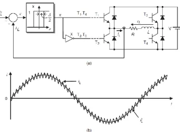
Hysteresis control uses the nonlinearity of a power converters induced by the switching states of a power converter. The proper switching state can be defined in order to insure an oscillation of the controlled quantities around the required one with a given hysteresis width. It can be used in simple applications, for example in case of basic current control but can also be generalized to more complex systems like in direct power control (DPC) [41]. Usually this type of controller is implemented with analog electronic devices. Indeed, an implementation on a digital platform, required a very high sampling frequency to properly control variations of the controlled quantities. Moreover, the switching frequency is variable in such control for a fixed hysteresis width but note that there are some possible modifications of this control strategy to achieve a fixed switching frequency.
Figure 2-8 shows waveforms for an hysteresis current control applied to a single phase inverter. The controlled current is the load current (𝑖𝐿). This value is compared to the reference (𝑖𝐿∗). The calculated difference (error 𝜀) pass through an hysteretic comparator. If the error reached the upper limit (𝛿/2), the controller turns on 𝑇1 and 𝑇4 and turns off the other two switches. The opposite command is applied when the error is less than the lower limit −𝛿/2). It can be observed from. Figure 2-8-b that the load current follows its reference with a pick to pick oscillation equal to the hysteresis width.
9
Figure 2-8 Hysteresis current control for a single-phase inverter. (a) Control scheme. (b) Load current
2.3.2. Linear control using PWM
The power converters are linear switched systems. From an average point of view, at the switching frequency scale, they can be linearized. With such approach, it is possible to use any linear controller with a PWM or a space vector modulator and proportional integral (PI) controllers are commonly used.
2.3.3. PI/IP control
Independent PI controllers are well suited to control uncoupled MIMO system quantities. This is natural for current control of uncoupled multicell power converters but for coupled ones, a decoupling strategy must be applied.
Authors in [1] use PI controllers to control a multicellular uncoupled parallel inverter in d,q axis in order to easily control the active and reactive power delivered to the grid. In these axis the system equations are coupled. Authors proposed a control strategy defined by elements of Figure 2-9 where we can see coupling effects between the two axis. Nevertheless, they used PI controllers for each axis without taking into account the coupling effects. They assumed these effects like disturbances. Note that effects of coupling are not studied and discussed in this reserch.
10
Figure 2-9 Diagram of the decoupled PQ Control
A current decoupling strategy is proposed in [2]. Authors use a classical PI controller to control the fictitious decoupled quantities of multicell power converter as shown in Figure 2-10. For this purpose, they diagonalized the inductance matrix (the mathematical representation of the coupled inductor) by using two transformations matrix (𝑇) and its inverse (𝑇−1). These transforms lead to calculate fictitious currents for which an independent PI controller can be applied. This document does not deal with the problem of the sensitivity of the control with regard to uncertainties on the knowledge of the model.
Figure 2-10 Block diagram of the decoupled control strategy of a multicell power converter This control technique will be used in this PhD but an addition will be made concerning the sensitivity study to the parameters of the model.
2.3.4. State space control
The state space control is suitable for multi inputs multi outputs (MIMO) systems, and the multicell power converter is a MIMO system. Authors in [3] use state feedback to control the
11
sharing of currents between cells as shown in Figure 2-11. The idea behind the state feedback is to calculate the control input (𝑢) by multiplying all the states ( ) by a gains value (𝒖 = −𝑲 𝒙).
In this example all cells currents are measured and the difference with one-nth of the total required output current is calculated. Then, the gain matrix (𝑲 𝑠 ) is applied and give sharing correction component of the duty cycle (𝑑𝑖). The output voltage control loop (duty cycle 𝐷) gives the global identical duty cycles 𝐷𝑖 applied to each cell. In other words, the current loop is used to control the differential mode of the currents and the voltage loop is used to control the common mode. In this paper authors did not study neither the sensitivity to the parameters of the model neither the impact of the coupling effect on this control strategy.
Figure 2-11 current sharing and voltage regulation for n-arm buck converter
The technique proposed in [4] is concerned with the control of a three level inverter (with no magnetic coupling) by state feedback. The control is designed for small signal in 𝑑 − 𝑞 axis. In this paper authors used linear quadratic program ( 𝑄𝑅) technique to find the controller gains.
Based on these works, we will use in this PhD two different ways to design the state space feedback controller. In the first method, we use pole placement with some constraints to deal with the high degree of freedom of our system. In the second approach, we use linear quadratic regulator ( 𝑄𝑅) technique to find the optimal controller’s gains. In addition, an in-depth analysis of the sensitivity to uncertainties on the knowledge of the system parameters will be conducted as well as an analysis of the coupling effects .
2.4. Model Predictive Control
Model predictive control (MPC) is playing a great role in the control of systems. It is used in many applications [42]–[45]. The main feature of MPC is to be able to deal with nonlinear, constrained and multi-input multi-outputs systems.
12
Mainly, in the field of power electronics, the MPC principles make it as a talented control substitute for power converters and machine drive [5], [46] because of its numerous advantages:
Its concepts are spontaneous and easy to understand.
It can deal the control of converters with multi inputs, multi output and states (currents, voltage, power, etc.)
Nonlinearity and constrained can be included in MPC in an easy way
2.4.1. Basic principles of Model Predictive Control
The principle of MPC is illustrated in the Figure 2-12. At time-step 𝑘 state-values are acquired. Based on the model and on the cost function the optimal switching vector sequence is calculated and the future states are predicted until the end of prediction horizon (𝑘 + 𝐻𝑝). At time-step 𝑘, the
first calculated optimal control input 𝑢 𝑘 of the switching sequence (the output of the controller for a power converter) is applied to the system. This procedure is repeated at each time-steps with new measurements while moving the prediction horizon by one step to keep the same length of the horizon (𝐻𝑝).
Figure 2-12 MPC principle The principle of MPC is based on:
The system model, to predict the future behavior of variables for a specific horizon called prediction horizon (𝐻𝑝). A discrete model is needed for MPC and can take the form of a discrete state-space model. The model can be either linear or nonlinear.
𝒙 𝑘 + 1 = 𝑓 𝒙 𝑘 , 𝒖 𝑘 (2-1) 𝑘 − 1 𝑘 𝑘 + 1 𝑘 + 2 𝑘 + 𝐻𝑝 𝑢 𝑘 − 1 𝑢 𝑘 𝑢 𝑘 + 1 𝑢 𝑘 + 𝐻𝑝 Past Future Reference Output /states
13
𝒚 𝑘 = 𝑓 𝒙 𝑘 , 𝒖 𝑘 (2-2)
The cost function to specify the desired behavior of the system. The cost function can customize the behavior of the system, and can include the references, the states and the future control input as in equation (2-3). The cost function can be in quadratic programing (𝑄𝑃) or linear programing ( 𝑃).
𝐽 = 𝑓 𝒙 𝑘 , 𝒖 𝑘 … … . . 𝒖 𝑘 + 𝐻𝑝 (2-3)
The minimization of the cost function to find the optimal actuating signal. The optimization of the cost function along a specific horizon (𝐻𝑝) subjected to the dynamic
of the system (model) and a specific constraint will result in an optimal switching vectors (in power electronics applications) from instant 𝑘 to 𝑘 + 𝐻𝑝 . Appling only
the first optimal switching vector 𝑘 to the power converter. 𝑚𝑖 𝑢 𝐽 subjected to: 𝑘 + 1 = 𝑨 𝑘 + 𝑩 𝑢 𝑘 𝑦 𝑘 = 𝑪 𝑘 + 𝑢 𝑘 0 ≤ 𝑘 ≤ 𝑖𝑢𝑝 𝑢 𝑘 ∈ [0,1] (2-4)
The constraints that can be applied on control input (𝑢 𝑘 ) and states ( 𝑘 ) represent the main advantage of MPC. In a power converter, the state constraints can be for example the voltage in a flying capacitor converter or the currents in the cell for a multicell converter. The control input can be a continuous quantity which represents the duty cycle if a PWM modulator is used. In this case, the constraint will be applied on the duty cycle (𝑢 𝑘 = 𝑑 𝑘 ∈ [0,1]). For a finite number of control input, MPC becomes Finite control set MPC (FCS-MPC). In this case, the constraints will be on the cell states with only 2 possible values (𝑢 𝑘 = 𝑆 𝑘 ∈ {0,1})
The search for an optimal solution is carried out at each sampling instants, with new measurements and gives a new optimal switching vector. This is called receding horizon strategy.
2.4.2. Finite control set MPC
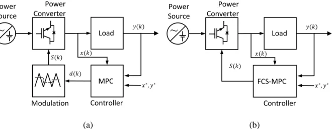
MPC with Continuous Control Set applied to a power converter requires a PWM modulator as shown in Figure 2-13-a. It has a high computational cost as control inputs are continuous functions. Conversely, FCS-MPC with a defined number of switch states combinations that can be applied to the converter and thus to the model does not need a PWM modulator as shown in Figure 2-13-b and has a lower computational cost. One advantage of FCS-MPC is that the switching actions are taken in the optimization problem and can be assumed as a constraints on the control input [46]. The other is the reduced number of control set. Nevertheless, this number depends on the prediction horizon and on the topology of the power converter. For example, for a one step prediction horizon and a one cell power converter the control set will be 𝑆 = 0 𝑜𝑟 1. To predict the states at 𝑘 + 1 we have thus two prediction states 𝑠=0𝑝 𝑘 + 1 and 𝑠=1𝑝 𝑘 + 1 . But when the prediction horizon is
![Figure 2-5 phase currents of three cells parallel multicell converter: a) uncoupled b)coupled [6]](https://thumb-eu.123doks.com/thumbv2/123doknet/14699880.746810/29.918.161.673.463.759/figure-phase-currents-parallel-multicell-converter-uncoupled-coupled.webp)