HAL Id: tel-03151257
https://tel.archives-ouvertes.fr/tel-03151257
Submitted on 24 Feb 2021HAL is a multi-disciplinary open access archive for the deposit and dissemination of sci-entific research documents, whether they are pub-lished or not. The documents may come from teaching and research institutions in France or abroad, or from public or private research centers.
L’archive ouverte pluridisciplinaire HAL, est destinée au dépôt et à la diffusion de documents scientifiques de niveau recherche, publiés ou non, émanant des établissements d’enseignement et de recherche français ou étrangers, des laboratoires publics ou privés.
Integrated building fault detection and diagnosis using
data modeling and Bayesian networks
Tianyun Gao
To cite this version:
Tianyun Gao. Integrated building fault detection and diagnosis using data modeling and Bayesian networks. Automatic Control Engineering. Ecole nationale supérieure Mines-Télécom Lille Douai, 2020. English. �NNT : 2020MTLD0010�. �tel-03151257�
Annexe 1 : Page de garde mémoire N◦ d’ordre :2020MTDL0010
IMT L
ILLED
OUAIU
NIVERSITE DEL
ILLETHESE
présentée en vue d’obtenir le grade deDOCTEUR
en
Displine : Automatique, Génie Informatique, Traitement du Signal et Images par
Tianyun GAO
DOCTORAT DE L’UNIVERSITE DE LILLE DELIVRE PAR IMT LILLE DOUAI
Titre de la thèse :
Integrated building fault detection and diagnosis
using data modeling and Bayesian networks
Soutenue le 24/11/2020 devant le jury d’examen :
Président : LERAY Philippe Professeur Polytech’Nantes
Rapporteure : PERA Marie Cécile Professeure U Franche-Comté
Rapporteur : SAELENS Dirk Professeur KU Leuven
Directeur de thèse LECOEUCHE Stéphane Professeur IMT Lille Douai Co-encadrant : BEGUERY Patrick Ingénieur de recherche Schneider Electric Co-encadrant : MARIE Sylvain Ingénieur de recherche Schneider Electric Co-encadrant : THEBAULT Simon Ingénieur de recherche CSTB
Examinatrice : DELCROIX Véronique Maître de Conférences UPHF
Laboratoire(s) d’accueil :
Unité de recherche CERI Systèmes Numériques d’IMT Lille Douai Ecole Doctorale SPI 072
Résumé
Dans les systèmes de chauffage, de ventilation et de climatisation (CVC, en anglais HVAC pour « Heating, Ventilation and Air Conditioning »), les défauts des équipements et les er-reurs de fonctionnement causent des problèmes de confort et un gaspillage d’énergie. Pour aider les gestionnaires d’installations à identifier et à corriger plus efficacement les défauts, il est essentiel de disposer d’un outil de détection et de diagnostic automatique de défauts (AFDD), capable de détecter automatiquement les problèmes de confort et d’énergie et d’en identifier les causes.
Les méthodes AFDD existantes se concentrent principalement sur la détection et le diagnos-tic de défauts au niveau des équipements. Peu d’attention n’est accordée au diagnosdiagnos-tic au niveau du bâtiment global, qui permet une détection plus efficace en s’appuyant sur l’inter-dépendance entre les équipements tout au long de la chaîne de distribution d’énergie. Cette thèse propose une nouvelle méthode AFDD pour les bâtiments, basée sur les données d’exploitation collectées par les systèmes de gestion technique du bâtiment (GTB, en anglais BMS pour « Building Management System »). Cette méthode est conçue autour d’un réseau bayésien qui permet de détecter les défauts des équipements HVAC en s’appuyant sur une meilleure décision basée sur la fusion des informations et des données provenant des dif-férents niveaux de composants. Cela permet de réaliser un diagnostic de défaut intégré de la globalité du bâtiment. Une originalité importante de cette contribution porte sur l’exploi-tation des historiques de fonctionnement et des techniques d’apprentissage pour aider au paramétrage automatique de l’outil de détection.
Notre méthodologie comprend les deux parties suivantes :
1. Une nouvelle manière systématique de transférer des informations de topologie de sys-tèmes de bâtiment et des connaissances d’experts pour la construction modulaire du réseau bayésien.
2. Une nouvelle approche pour intégrer des détections de défaut au niveau des équipements dans un réseau bayésien de diagnostic du bâtiment complet. Nous utilisons une méthode de régression pour les équipements centraux (par exemple, groupe froid, chaudière et central traitement d’air), apprise sur des données de fonctionnement normal collectées lors d’un test de mise en service. Pour les équipements dans les zones d’usage, nous utilisons un modèle probabiliste des corrélations entre données de consigne et de mesure.
Une fois le réseau mis en place et les données – mesures et prédictions – collectées, le réseau est à même de calculer la probabilité de différents défauts dans le système bâtiment complet, et d’en identifier les causes les plus probables.
Nous avons testé ce nouvel outil de diagnostic des défauts sur des données provenant de simulation et de deux bâtiments réels afin de tester les performances en termes de détection. Les résultats montrent que notre approche est capable de gérer facilement un grand nombre d’équipements et d’identifier correctement les causes à partir des données mesurées et
pré-dites au niveau des équipements.
Par rapport aux approches de type AFDD existantes, cette nouvelle méthode offre les avan-tages suivants :
1) La structure modulaire et la méthodologie généralisée permettent à cette méthode d’être appliquée à une grande variété de systèmes CVC et de bâtiments.
2) Cette approche relie les défauts d’équipement aux symptômes de confort du bâtiment perceptibles par les occupants.
3) Le système HVAC est diagnostiqué dans son ensemble au lieu de le faire équipement par équipement.
4) En connectant chaque violation de point de consigne de confort avec les défauts des équi-pements, et en recherchant les défauts racines pour chaque défaut d’équipement de zone, le nombre total d’alarmes est grandement réduit.
5) Les gestionnaires d’installations peuvent utiliser l’outil de manière interactive, en mettant à jour les données de certains nœuds du réseau bayésien sur la base d’observations terrain.
Abstract
Heating, ventilation, and air-conditioning (HVAC) equipment faults and operational errors result in comfort issues and waste of energy in buildings. In order to help the facility man-agers to identify and fix faults more efficiently, it is essential to have an Automatic Fault Detection and Diagnosis (AFDD) tool, able to automatically detect comfort and energy is-sues and identify the root faults.
Existing AFDD methods mostly focus on equipment-level fault detection and diagnostics. Almost no attention is given to building level fault diagnosis, considering inter-dependency between equipment through the energy distribution chain.
This thesis proposes a new building AFDD method based on operation data collected by Building Management Systems (BMS). The method uses Bayesian Network to achieve building-level integrated fault diagnosis and equipment-building-level data-driven fault detection by infor-mation fusion of data collected from different equipment of HVAC systems. An important contribution relates to the use of operating data and learning techniques to automatically tune some parameters of the detection tool.
Our methodology is composed of the following two parts:
1. A new systematic way of transferring building system topology information and expert knowledge to a Bayesian Network.
2. A novel approach for integrating equipment-level fault detection results into a building-level fault diagnosis Bayesian network. We use regression methods for central equipment (e.g. chiller, boiler, and Air Handling Unit), learned from normal operation data collected during a commissioning test. For room equipment, we use probabilistic models of correla-tions between control and measurement data.
Once the fault diagnosis network is set up and all of the evidence is collected, the network is able to calculate the probability of different faults and identify the most probable root faults. We implemented the fault diagnostics Bayesian network on one simulation data set and two real building operation data sets to test the performance of the AFDD method. The results show that the method is able to easily handle large numbers of equipment, and correctly identify root causes with given evidence.
Compared to existing AFDD methods, the new method provides the following benefits: 1) The modular structure and generalized methodology allow the method to be applied to wide variety of HVAC systems.
2) The method connects equipment faults to building comfort symptoms perceivable by occupants.
4) By connecting comfort set point violation with equipment fault, and tracing root fault of room equipment failure, the total number of alarms is reduced.
5) Facility managers can use the tool in an interactive way, thanks to the capability to post evidence in the Bayesian network based on field investigation findings.
Acknowledgment
I would like to express my deepest appreciation to my supervisors, Sylvain Marié, Patrick Béguery, Simon Thébault, and Stéphane Lecoeuche. Without their guidance, encourage-ment, and support, I would not have been able to complete the thesis.
My supervisor Professor Stéphane Lecoeuche gave me essential guidance in defining the re-search scope, consolidating the theoretical foundation, and structuring the thesis manuscript. My co-supervisor and directors at CSTB provided me excellent research infrastructure, learn-ing opportunities, and group cooperation support. I would like to thank Simon Thébault for his consistent encouragement and support. I also would like to thank Antoine Breitwiller for providing the data pre-processing tool TSAR. Last but not least, I sincerely thank my directors Stéphanie Derouineau and Jean Christophe Visier, and all the colleagues whom I worked with, for providing me such a pleasant working experience at CSTB.
My co-supervisors from Schneider Electric consistently supported my research interest and provided data for the tests. Sylvain Marie was deeply involved in the discussion of data modeling and Bayesian networks, which helped me shape the integrated FDD methodology. Patrick Béguery provided me the simulation model of Green O Valley building and helped me collect operation data in this building, which were used to test the developed method. I thank Henri Obara who helped coordinate with the facility managers in Green O Valley building and set up FDD tests with the Air Handling Unit. Thanks to Bartosz Boguslawski and other colleagues at Schneider Electric for the interesting discussions on data modeling and fault detection.
I appreciate the feedbacks and comments from my reviewers Dirk Saelens and Marie-Cécile Pera, and other jury members, Philippe Leray, and Véronique Delcroix. Thanks a lot for all the kind and encouraging words as well as inspiring questions.
Words can not express my gratitude to my husband who took over so much work at home to allow me to invest all my time and energy into the research, my parents and parents-in-law for helping take care of my new-born baby in his first year, and my two children for being so lovely and understanding. Without the full-hearted support of my whole family, it would not be possible for me to complete the degree. I love you with all my heart!
Contents
1 Introduction 17
1.1 Background . . . 17
1.1.1 Causes of building performance gap . . . 17
1.1.2 The need for an automatic fault detection and diagnostics tool . . . 20
1.2 Motivation . . . 21
1.2.1 State of the art of commercial fault detection solutions . . . 21
1.2.2 Illustration and limitations of existing solutions . . . 23
1.2.3 Research questions and scope . . . 23
1.3 Contribution . . . 25
1.4 Benefits of the new AFDD method . . . 27
1.5 Manuscript organization . . . 27
1.6 Notation . . . 27
2 State of the art of building AFDD methods 29 2.1 Overview of automatic fault detection and diagnosis methods . . . 29
2.1.1 Quantitative model based methods . . . 30
2.1.2 Qualitative model based methods . . . 32
2.1.3 Process history based methods . . . 32
2.2 Limitation of existing methods and need of new methods . . . 39
2.2.1 Lack of building level diagnostics . . . 39
2.2.2 Choice of Bayesian Network . . . 40
2.3 Bayesian networks for fault detection and diagnosis . . . 40
2.3.1 Application of Bayesian networks in fault diagnosis . . . 40
2.3.2 HVAC fault diagnosis using Bayes methods . . . 41
2.3.3 Limitation of existing application of Bayesian Network . . . 42
3.1 Bayesian Network Theory . . . 44
3.1.1 Probability . . . 44
3.1.2 Random variable . . . 44
3.1.3 Bayesian networks . . . 45
3.1.4 Inference . . . 46
3.1.5 Hard evidence and virtual evidence . . . 49
3.2 HVAC fault diagnosis network . . . 50
3.2.1 Room radiator system fault diagnostics . . . 50
3.2.2 Fault diagnostic Bayesian network of a generic HVAC sub-system . . 54
3.2.3 Examples of specific HVAC sub-systems . . . 59
3.2.4 Application of the fault diagnosis network concept . . . 63
3.3 Obtaining evidence from data . . . 75
3.3.1 Hard evidence . . . 75
3.3.2 Virtual evidence . . . 78
3.3.3 Summary of methods to compute fault detection evidence . . . 84
4 Validation with simulation data 85 4.1 Description of simulation data . . . 85
4.2 Implementation . . . 86
4.2.1 Structure . . . 86
4.2.2 Parameters. . . 89
4.3 Evidence . . . 90
4.3.1 Overview of evidence obtained from data . . . 90
4.3.2 Hard evidence . . . 91
4.3.3 Virtual evidence: AHU heating / cooling process . . . 92
4.3.4 Virtual evidence: FCU heating / cooling process . . . 94
4.4 Inference results . . . 98
4.4.1 Fault 1. AHU1 heating valve stuck close. . . 98
4.4.2 Fault 2. chilled water pump 2 (serving rooms) failure . . . 100
4.4.3 Fault 3. room1 cooling valve stuck close . . . 101
4.4.4 Fault 4. room 4, 19, and 24 FCU cooling coil under-dimensioned . . . 102
4.4.5 Summary . . . 103
4.5 AFDD performance evaluation . . . 103
5.1 Description of test data . . . 107
5.1.1 Data collection . . . 107
5.1.2 Data pre-processing . . . 108
5.1.3 Data visualization and manual anomaly detection . . . 110
5.1.4 Faults description. . . 110
5.2 Test of Porte-de-Retz building . . . 112
5.2.1 HVAC system topology and operation mode . . . 112
5.2.2 Implementation of fault diagnostics network . . . 113
5.2.3 Evidence . . . 115
5.2.4 Building level diagnosis results . . . 117
5.3 Test of GreenOValley building. . . 123
5.3.1 HVAC system topology and operation mode . . . 123
5.3.2 Implementation of the fault diagnosis network . . . 124
5.3.3 Evidences . . . 126
5.3.4 Building level diagnosis results . . . 129
5.4 Benefit of the fault diagnosis Bayesian network . . . 132
5.4.1 Easiness of implementation based on HVAC system topology . . . 132
5.4.2 Integrate operation data of all equipment in the building . . . 132
5.4.3 Integrate maintenance information into fault diagnostics . . . 132
5.4.4 Reveal root causes of building comfort issues. . . 132
5.4.5 Integrate field observations for an interactive diagnosis process . . . . 132
5.4.6 Reducing alarms . . . 132
6 Conclusion and Perspectives 134 6.1 Contributions . . . 134
6.2 Research perspectives . . . 135
6.2.1 Automatic design of the Bayesian network from building information 135 6.2.2 Extension of the Bayesian network . . . 135
6.2.3 Bayesian network parameter setting . . . 136
6.2.4 Method of room equipment fault detection . . . 136
6.2.5 Room equipment correlation distribution model online update . . . . 136
6.2.6 Performance test of the fault diagnostics Bayesian network . . . 138
6.3 Applications perspective . . . 138
A.1 Green O Valley building . . . 140
A.1.1 Building plan . . . 140
A.1.2 Building envelope . . . 140
A.1.3 HVAC system: Overview . . . 142
A.1.4 HVAC system: Heating and cooling generation . . . 143
A.1.5 HVAC system: Hot water and chilled water distribution . . . 143
A.1.6 HVAC system: Ventilation system . . . 144
A.1.7 HVAC system: Room heating and cooling device . . . 144
A.2 Porte de Retz building . . . 144
A.2.1 Building plan . . . 144
A.2.2 Building envelope . . . 145
A.2.3 HVAC system: Overview . . . 146
B Data visualization of test buildings 147 B.1 Porte-de-Retz building . . . 147
B.1.1 Room temperature heat map . . . 147
B.1.2 Room device daily operation benchmark . . . 148
B.1.3 Central equipment daily energy benchmark . . . 152
B.2 GreenOValley building . . . 152
B.2.1 Room temperature heat map . . . 152
B.2.2 Room device daily operation benchmark . . . 153
B.2.3 Central equipment daily energy benchmark . . . 156
List of Figures
1.1 Causes of building performance gap . . . 18
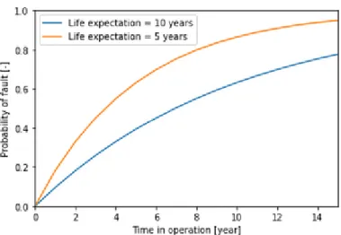
1.2 Number of faults in building’s life cycle . . . 20
1.3 Alarm list of a chiller from the manufacture TRANE. . . 21
1.4 Example of BMS system, EcoStruxure™ Building Operation from Schneider Electric. . . 22
1.5 Fault detection system topology and alarms data processing principles . . . . 24
1.6 Structure of the new fault detection solution . . . 26
2.1 Classification scheme for AFDD methods . . . 30
2.2 Diagram of real time energy diagnostics System, O’Neill et al., 2011 . . . 31
2.3 Demonstration building Vaucanson, Béguery et al., 2017. Model in IDA-ICE 3D view. . . 31
2.4 Demonstration building Vaucanson, Béguery et al., 2017. Fault detection tool user interface . . . 31
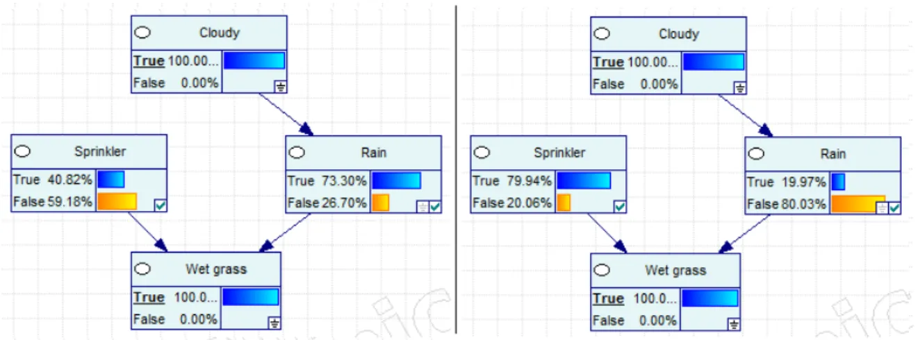
3.1 Bayesian network for the ’wet grass’ example. . . 45
3.2 Inference results of Example 1-2: left (a), right (b). . . 48
3.3 Inference results of Example 1-2: left (a) virtual evidence 10% rain, 90% no rain; (b) virtual evidence 1% rain, 99% no rain; . . . 49
3.4 Concept model of Room radiator system. . . 50
3.5 The heat load distribution of Building Enclosure normal case (left) and fault case (right) . . . 52
3.6 Fault diagnosis Bayesian Network of a room radiator system . . . 53
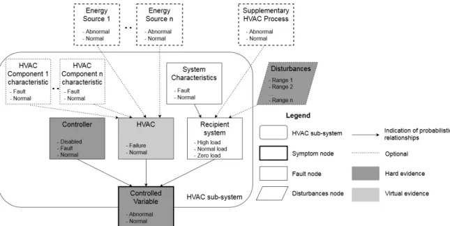
3.7 Generic concept model of HVAC sub-systems. . . 54
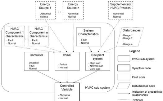
3.8 Fault detection Bayesian network of an HVAC sub-system. Dotted lines indi-cate optional nodes. . . 55
3.9 Fault probability of an equipment increased with years in operation. . . 59
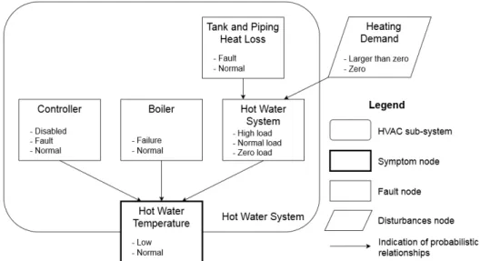
3.10 Concept model of a hot water boiler system . . . 59
3.11 Fault diagnosis Bayesian network of a hot water boiler system . . . 60
3.13 Fault diagnosis Bayesian network of a pump hydraulic system . . . 60
3.14 Example of VFD pump curve . . . 61
3.15 Concept model of constant air flow ventilation system. . . 61
3.16 Fault diagnosis Bayesian network of constant air flow ventilation system . . . 61
3.17 Concept model of a chiller chilled water system . . . 62
3.18 Fault diagnosis Bayesian network of a chiller chilled water system. . . 62
3.19 Room radiator system fault diagnosis network concept . . . 65
3.20 Room radiator system fault diagnosis inference case 1 . . . 69
3.21 Room radiator system fault diagnosis inference case 2 . . . 70
3.22 Room radiator system fault diagnosis inference case 3 . . . 71
3.23 Room radiator system fault diagnosis inference case 4 . . . 72
3.24 Room radiator system fault diagnosis inference case 5 . . . 73
3.25 Room radiator system fault diagnosis inference case 6 . . . 74
3.26 Fault detection Bayesian network of an HVAC sub-system. (Dotted lines in-dicate optional nodes.) . . . 75
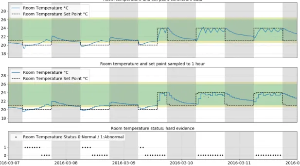
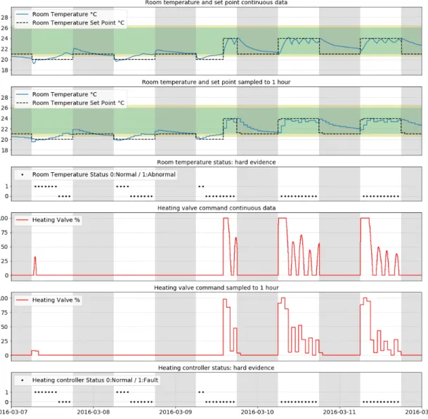
3.27 Controlled variable hard evidence: Porte de Retz building FCU28 room tem-perature . . . 76
3.28 Example of a room unit of fan coil unit. . . 76
3.29 Controller hard evidence: Porte de Retz building FCU28 heating control . . . 78
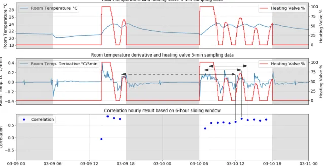
3.30 Room equipment virtual evidence: Porte de Retz building FCU28 heating process . . . 83
4.1 Simulated GreenOValley building system topology . . . 86
4.2 Simulated Green-O-Valley building block diagram . . . 87
4.3 Simulated Green-O-Valley building diagnostic network . . . 88
4.4 Commissioning test and prediction with initial model of AHU heating process 92 4.5 On-line updated prediction and fault detection of AHU heating process . . . 93
4.6 Probability of AHU1 heating process fault . . . 93
4.7 Prediction and fault detection of AHU heating process, zoom into one day.. . 94
4.8 The probability distribution of correlations, room temperature derivative v.s. heating command. . . 95
4.9 The probability distribution of correlations, room temperature derivative v.s. cooling command. . . 95
4.10 Probability of room heating process failure . . . 96
4.11 Probability of room cooling process failure . . . 96
4.12 Correlation between room temperature derivative and heating command in room 3 . . . 97
4.13 Correlation between room temperature derivative and heating command in
room 4 . . . 97
5.1 Data pre-processing of room temperature data (1) . . . 109
5.2 Data pre-processing of water temperature data (2) . . . 109
5.3 During heating season, room 34 valve stuck close compared to Room 33 normal.111 5.4 Heat pump heating / cooling mode reversed, observed in Room 21 and Room 6111 5.5 HVAC system topology of Port-de-Retz building . . . 112
5.6 Fault diagnosis network of Port-de-Retz building . . . 114
5.7 Retz building room time series correlation heat map . . . 116
5.8 Retz building room time series correlation histogram . . . 116
5.9 Probability distribution of correlations fit to Gaussian Mixture Model . . . 117
5.10 Retz building, building level diagnosis inference results 1: valve faults caus-ing low room temperatures. . . 119
5.11 Retz building, building level diagnosis inference results 2 with missing data: heat pump off causing high room temperatures. . . 120
5.12 Retz building, room comfort (normal or low temperature) in each room and the root causes. . . 121
5.13 Retz building, number of hours of room low temperature and the root causes. 121 5.14 Retz building, room comfort (normal or high temperature) in each room and the root causes. . . 122
5.15 Retz building, cooling season, number of hours of room high temperature and the root causes. . . 123
5.16 HVAC system topology of GreenOValley building . . . 124
5.17 Fault diagnosis network of GreenOValley building . . . 125
5.18 GreenOValley building, AHU04, heating coil: commissioning test and collec-tion of initial training data . . . 127
5.19 GreenOValley building, AHU04, heating coil: prediction and drift detection. (1) 8:00am to 8:40am (2) 9:00am to 9:40am (3) 15:00pm to 17:30pm . . . 128
5.20 GreenOValley building, AHU04, heating coil: prediction and drift detection . 129 5.21 GreenOValley building, AHU04, heating coil, probability of failure . . . 129
5.22 GreenOValley building, building level diagnosis inference results 1: AHU04 mechanical fault (valve) causing low supply air temperature.. . . 130
5.23 GreenOValley building, building level diagnosis inference results 2: AHU01, 02, 03, 04, circulation pump turned off causing low supply air temperature. . 131
6.1 Update of correlation distribution model every two weeks. Data from real building Port-de-Retz. . . 137
A.1 Construction plan of Green O Valley building. . . 140
A.2 Simulation of windows shades in Green O Valley building . . . 141
A.3 Parameters of thermal bridges in Green O Valley building . . . 142
A.4 HVAC system topology of Green O Valley building . . . 142
A.5 Heat pumps in Green O Valley building, BMS graphics. . . 143
A.6 AHUs for the office area in Green O Valley building, BMS graphics. . . 144
A.7 Construction plan of Porte de Retz building . . . 145
A.8 Envelope properties of Porte de Retz building . . . 145
A.9 HVAC system topology of Port-de-Retz building . . . 146
B.1 Room temperature heat map, Porte-de-Retz building . . . 147
B.2 Room temperature and set point scatter plot, Porte-de-Retz building . . . 148
B.3 Room temperature and set point scatter plot, Porte-de-Retz building . . . 149
B.4 Room heating and cooling command scatter plot, Porte-de-Retz building . . . 150
B.5 Room heating and cooling command scatter plot, Porte-de-Retz building . . . 151
B.6 Daily energy benchmark of Porte-de-Retz building. . . 152
B.7 Room temperature heat map, GreenOValley building . . . 153
B.8 Room temperature and set point scatter plot, GreenOValley building . . . 154
B.9 Room heating and cooling command scatter plot, GreenOValley building . . 155
B.10 Daily energy benchmark of AHUs, GreenOValley building . . . 156
List of Tables
2.1 Summary of data driven AFDD studies, part 1. . . 34
2.2 Summary of data driven AFDD studies, part 2. . . 35
3.1 Room temperature in condition of three components of the room radiator sys-tem . . . 51
3.2 Root causes of radiator failure. Valve and heat exchanger fault refer to valve stuck close or heat exchanger blockage. . . 52
3.3 Conditional probabilities of Room node in the room radiator system, obtained from simulation results as an example. . . 53
3.4 Conditional probabilities of Controlled Variable . . . 56
3.5 Conditional probabilities of ’HVAC’ . . . 57
3.6 Summary of HVAC sub-system fault diagnostics Bayesian Networks . . . 63
3.7 Prior probabilities of root fault nodes in the room radiator system application 64 3.8 Prior probabilities of the disturbance node in the room radiator system appli-cation . . . 66
3.9 Conditional probabilities of Room node in the room radiator system application. 66 3.10 Conditional probabilities of Hot Water System node in the room radiator sys-tem application. . . 66
3.11 Conditional probabilities of Piping System node in the room radiator system application. . . 66
3.12 Fault diagnosis inference results. The objective of the inference process is to get an updated probability for all root fault nodes. Posted evidence is marked in gray. Root faults are marked in red. Most probable faults are in dark red color, and less probable faults are in light red color. . . 68
3.13 Methods and required data for obtaining hard evidence . . . 84
3.14 Methods and required data for obtaining virtual evidence (* indicates op-tional data.) . . . 84
4.1 Prior probabilities of root fault nodes in the whole building test case . . . 89
4.2 Overview of the evidence in the Green-O-Valley simulation case study. . . 91
4.4 Fault diagnosis results of fault 2: rooms chilled water pump failure . . . 100
4.5 Fault diagnosis results of fault 3: room1 cooling valve stuck close . . . 101
4.6 Fault diagnosis results of fault4 : room 4, 19, and 24 cooling capacity not enough102 4.7 Confusion matrix . . . 104
4.8 Fault detection and diagnosis overall accuracy (ACC) . . . 105
4.9 Fault detection and diagnosis sensitivity (TPR), precision (PPV), and F1 score 105 5.1 Prior probabilities of root fault nodes, Porte-de-Retz building. . . 113
5.2 Set points of controlled variables, Porte-de-Retz building . . . 115
5.3 Room heating cooling process fault detection . . . 117
5.4 Fault diagnosis inference results, Porte-de-Retz building, 02/03/2016-10AM. 118 5.5 Prior probabilities of root fault nodes, Porte-de-Retz building . . . 126
5.6 Set points of controlled variables, GreenOValley building . . . 126
A.1 Wall properties of Green O Valley building . . . 141
A.2 Window properties of Green O Valley building . . . 141
Abbreviations
AFDD Automatic Fault Detection and Diagnosis HVAC Heating Ventilation and Air Conditioning BMS Building Management System
VAV Variable Air Volume
PI control Proportional–Integral control COP Coefficient Of Performance PCA Principle Component Analysis SVR Support Vector Regression
KPCA Kernal Principle Component Analysis SPE Squared Prediction Error
SVM Support Vector Machine
DT Decision Tree
ANN Artificial Neural Network LR Linear Regression
AR Auto-Regressive
ARX Auto-Regressive Exogenous
NA Not available
EWMA Exponentially Weighted Moving Average TFDK Tree-structured Fault Dependence Kernel
BN Bayesian Network
SAX Symbolic Aggregate Approximation PMF Probability Mass Function
AHU Air Handling Unit
HMI Human Machine Interface FCU Fan Coil Unit
MTBF Mean Time Before Failure VFD Variable Frequency Drive RMSE Root Mean Square Error COV Change Of Value
Chapter 1
Introduction
This thesis proposes a new Automatic Fault Detection and Diagnosis (AFDD) method for buildings based on operation data collected by Building Management Systems (BMS). The method uses Bayesian Networks to integrate data from different components of the Heating Ventilation and Air-conditioning (HVAC) system, including equipment-level data-driven fault detection results, to achieve integrated fault diagnosis and information fusion. The introductory part of this work provides general background on the importance of building fault detection and diagnosis tools. It is followed by a state of art of existing AFDD solutions in the industry and their limitation, leading to the motivation behind this thesis and its main contributions.
1.1
Background
1.1.1 Causes of building performance gap
Buildings, industry, and transportation are the three main energy consumers in our soci-ety. About 40% of energy is consumed in buildings in the European Union1. And within buildings, the Heating, Ventilation and Air-conditioning (HVAC) systems consume the most energy. A lot of effort has been given to reduce energy consumption of HVAC systems in buildings. With the development of the sustainable design concept, high performance build-ing envelopes, and energy efficient heatbuild-ing and coolbuild-ing systems, today, the buildbuild-ing and construction industry has obtained a complete solution to low-energy building design. Var-ious standards and evaluation systems such as RT20122, EPBD3, LEED4defined calculation methods and key performance indicators to encourage green building design.
However, during operation, the actual energy consumption in many buildings are much higher than expected. Sometimes comfort is not guaranteed either. Room temperature set-points are not maintained, and some rooms are over-heated or over-cooled. The deviation of actual building comfort and energy performance from the designed performance is called building performance gap.
International Energy Agency (IEA) Annex,0071provided methods of conducting building
1. https://ec.europa.eu/energy/en/topics/energy-efficiency/buildings 2. RT2012 is the sustainable building design standard in France.
3. Energy performance of buildings directive (EPBD) gives guidance to European Union member countries to improve building energy performance.
energy performance assessment based on in-situ measurements. Van Dronkelaar et al.,2016
investigated the underlying causes of energy performance gap in non-domestic buildings. De Wilde,2014provided a framework to investigate the gap between predicted and mea-sured energy performance.
What are the problems that cause the building performance gap, and how can we fix them? To understand this, we need to differentiate between problems occurring in different phases of the building’s life time. Figure 1.1lists major problems that occur in design, construc-tion and operaconstruc-tion phase, respectively. To identify and fix the problems, one should follow a backward process, because construction and design issues can only be identified when operation faults are eliminated. Operational problems, as well as some of the construction problems (such as wrong sensor location) can be fixed by maintenance and repair. Most of the construction problems and design problems can only be fixed by system renovation, such as replacing the boiler, reconstructing the piping, and improvement of the building insulation.
Figure 1.1 – Causes of building performance gap
1.1.1.1 Operation problems
Wrong human behavior: The first problems to avoid are related to human behaviors. They include setting wrong configuration values in the building management system (BMS) such as set points and schedules, manually overriding equipment set points or parameters and forgetting to change them back, or keeping windows and doors open in cold or hot seasons. These are simple mistakes but the most common ones.
Control faults: If the BMS controller is not giving appropriate signals to operate the equip-ment, for example, if the radiator valve is not commanded to open when room temperature
is far below set point, it indicates a controller fault. Controller faults include controller failure, control algorithm error, and wrong control parameters, e.g. inappropriate Propor-tional–Integral (PI) controller parameters causing system oscillation. In practice, this kind of faults may exist for a very long time without being noticed, as long as no one complains about comfort problems. Controller faults are usually fixed by control specialists, e.g. in-staller or integrator of the building automation system.
HVAC equipment and BMS field devices faults: If the HVAC process is not functioning as expected despite the control signal being correct/appropriate, it indicates a fault of the HVAC equipment or the BMS field devices (sensors and actuators). A site visit is neces-sary to identify the fault, and mechanics will be hired to repair and change damaged parts. BMS field devices sensor faults include sensor drift, loose connection, damage caused by corrosion, or electric short cut. Damper and valve actuator faults include being stuck or leaking, and failure of motors. HVAC equipment faults include short circuit, overload, and mechanical degradation of electrical devices such as fans, pumps, and electric heaters, as well as mechanical issues of heat pumps, boilers, chillers, heat exchangers, such as over-pressurization, leakage, or blocking of pipes.
1.1.1.2 Construction problems
Sometimes, even when all operational faults are eliminated, the building is still not running as expected. Some rooms are constantly too cold or too warm, some Variable Air Volume (VAV) boxes are not getting enough air flow, or the chilled water system is not getting the designed water flow. In such cases, one must further investigate on site to look for construc-tion problems.
Construction problems have the following types. First, installation problems. For example, if a room sensor is installed above a radiator and does not represent the real room tempera-ture, then this room will always be too cold; if the VAV air outlet is covered by the suspended ceiling or some furniture, then the room will never get enough air supply. Second, mechani-cal components problems. A valve or pipe connector of wrong size or gas in the piping may significantly reduce the water flow and cause the chiller to only give out half of its cooling capacity. Third, building envelope problems. A thermal bridge, un-insulated door, or an opening on the window for running wires can cause significant heat loss such that the room temperature cannot be maintained.
1.1.1.3 Design problems
Sometimes, after everything has been done to fix operation and construction problems, the building still has difficulty maintaining comfort, or consumes much more energy than ex-pected. In such cases, one should check if there are problems in the building and system design. Such problems could be over-sized or undersized equipment, unbalanced air or water system, inefficient air distribution, etc. Such problems are caused by inaccurate de-sign simulation or dede-sign input, such as weather data, building and system properties (heat transfer coefficient, infiltration rate, Coefficient Of Performance (COP) of chiller), or occu-pancy profile. We henceforth refer to them as inherited building performance gap. These kinds of issues are not easy to prevent in the design phase, and can only be fixed by redesigning and modifying the system after the building is in operation.
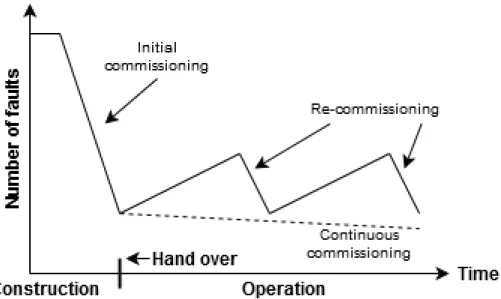
Figure 1.2 – Number of faults in building’s life cycle
1.1.2 The need for an automatic fault detection and diagnostics tool
Figure 1.2 illustrates the typical evolution of the number of faults in a building’s life cy-cle. At the end of the construction phase, during the initial commissioning, most faults of the system are eliminated. However, during the operation phase, faults accumulate again. Many faults in buildings remain undiscovered for a very long time, causing a big building performance gap. There are mainly two reasons for this:
— Lack of visibility: Facility managers don’t have a global view of how well the system performs. As long as the comfort in most rooms are maintained and all equipment are running, no action will be taken. High energy consumption and abnormal operation are not brought to their attention, mostly because there is no benchmark of normal energy consumption or normal operation to compare to.
— Labor intensive diagnostics: Typically, diagnostics rely on engineering experience and on-site inspection. In practice, the labor-intensiveness of these tasks is such that they are not routinely performed, and they may never be performed in most build-ings.
Periodic re-commissioning would be able to remove these faults and bring the building per-formance back to the level of the hand over state. In an ideal situation, monitoring-based continuous commissioning helps the building to maintain and even improve the perfor-mance during the whole operation phase.
Building management systems provide the technical basis for monitoring-based continuous commissioning. However, only recording operation data is not enough to help facility man-agers identify and fix faults efficiently. It is essential to have an automatic fault detection and diagnostics (AFDD) tool, which is able to automatically analyze the data, detect comfort and energy issues, and identify the most probable faults that are causing these issues.
We emphasize that the objective of such a tool is to help facility managers and maintenance personal find out faults more efficiently, but not to replace them with a fully automatic system. On-site investigation is still important and necessary to verify and fix faults in buildings.
1.2
Motivation
1.2.1 State of the art of commercial fault detection solutions
In most non-residential buildings, fault detection and diagnostics are based on alarms and historical data generated by the HVAC equipment and the BMS. In the last ten years, fault detection and diagnostics platforms started to emerge in the market. In this section, we will describe these three categories of fault detection solutions: HVAC equipment built-in fault detection, building management system alarming, and fault detection and diagnostics platform
1.2.1.1 HVAC equipment built-in fault detection
A lot of central HVAC equipment has embedded factory-made controllers. These controllers usually have their own fault detection and are able to send alarms to BMS through electri-cal signals or communication protocols. Since such fault detection solution including the algorithm and all necessary sensors is tailored to the specific equipment and tested in the factory, the results are usually very detailed and precise. Figure 1.3 gives an example of HVAC equipment alarms.
1.2.1.2 Building management system alarming
Today’s building automation systems have the capability to monitor all equipment on a central platform. On this platform people can view real-time values in graphics, change settings (set points, schedules, control parameters), and override commands (boiler, chiller, fan, and pump on-off, valve and damper opening degrees).
Figure 1.4 – Example of BMS system, EcoStruxure™ Building Operation from Schneider Electric.
With the help of the building automation engineering software, system integrator and fa-cility managers can program any alarms for specific applications, including out-of-range alarms and command failure alarms. Simple faults such as pump not running (command failure) or heating coil about to freeze (temperature out of range) can be detected with these alarms. The system also has built-in alarms for lost communication and wiring mistakes of sensors and actuators.
A few examples of mainstream building automation systems are: EcoStruxure™ Building Operation from Schneider Electric (as shown inFigure 1.4)5, Desigo™ from Siemens6, and WEBs-AX™ from Honeywell7.
1.2.1.3 Fault detection and diagnostics platform
New emerging fault detection platforms integrate with building management system (BMS), energy management system (EMS) and other systems to get operation data, and provide an-alytics and rule-based fault detection based on these data.
The market leaders include: SkySpark from SkyFoundry8and Clockworks from KGS
Build-5. https://www.se.com/fr/fr/product-range/62111-ecostruxure™-building-operation 6. http://w5.siemens.com/france/web/fr/sbt/ee/solutions-gestion-technique-batiment/desigo/pages/systeme-desigo.aspx 7. https://www.buildingcontrols.honeywell.com/Building-Automation-Systems/WEBs-N4-Software-Platform 8. https://skyfoundry.com/skyspark/
ing9. The latter is also integrated in EcoStruxure™ Building Advisor from Schneider Elec-tric10. Both systems connect to BMS, EMS, and other building systems through
communica-tion protocols, obtain online data, and run cloud-based automatic fault deteccommunica-tion programs. SkySpark provides an open platform, which allows facility managers to program automatic fault-detection rules. For example, they can generate an alarm if AHU supply-air temper-ature is not higher than mix-air tempertemper-ature when heating valve is open, indicating valve command failure or hot water unavailability. Clockworks is a cloud-based service of remote assistance by in-house engineers, relying on physical and data-driven models tailored to each building during commissioning.
1.2.2 Illustration and limitations of existing solutions
In order to illustrate the system topology of different fault detection solutions, the HVAC system of an office building is shown inFigure 1.5as an example. HVAC equipment fault detection, in this example the alarms from the heat pumps, are generated by the equipment embedded controller. Together with sensor, actuator, and meter data, the data generated in the field are collected in BMS, EMS, and other systems such as lighting. The fault detection platform integrates these systems to get data. Based on the data, fault detection is realized by expert rules.
The current system has the following limitations:
1) Alarms and rule-based fault detection logic are highly customized to specific equipment. An algorithm implemented in one building usually doesn’t apply to another building. A general method capable of addressing different systems is missing.
2) Rule-based fault detection methods are mostly focusing on detecting abnormal equip-ment behavior. However the connection between equipequip-ment fault and building comfort issues is usually missing. For example when room set point violation appears, the existing fault detection methods are not able to reveal the root cause.
3) In HVAC systems, the functionality of room devices are dependent on the central equip-ment. For example, if the boiler or the hot water pump is not working, the associated room radiators don’t work as well. The inter-dependency between equipment is usually not con-sidered in existing fault detection methods. Tracing causal relationship between equipment faults remain as a labor intensive manual work.
In practice, tracing root causes involves great amount of manual work and expert knowl-edge, including sorting big number of alarms, observing data trend log (time series) of spe-cific equipment in spespe-cific time period, as well as navigating between associated equipment.
1.2.3 Research questions and scope
In this research, we want to answer the following questions:
1) How can we automatically link comfort violation symptom to the root faults using BMS data? The root faults may be located in other part of the system.
2) How can we automatically identify abnormal behavior of an HVAC equipment from BMS data?
9. http://www.kgsbuildings.com/clockworks
Considering the practical condition in buildings, our methods need to fulfill the following requirements:
1) Very easy to adapt to various HVAC system types and typologies.
2) Very flexible with data availability, tolerant to missing data and data error.
Since it is a very challenging and wide topic, we limit our research scope to the followings: 1) Symptoms: We focus on comfort set point violation. We consider temperature as first step, and the method can be extended to include other comfort criteria, such as air quality measured by CO2.
2) Faults: It’s most important to identify the fault source equipment and fault categories, in order to help facility managers to set priorities of site investigation and be more efficient in finding the right professionals to fix the issues.
3) Building and HVAC systems: In this study we focus on non-residential buildings with common central HVAC systems. First deployment is based on two real office buildings, which are offered as test buildings by CSTB and Schneider Electric.
4) Data: Since the study is aiming at industry deployment in near future, we mainly consider commonly used sensors and actuators collected by BMS in non-residential buildings, with reasonable time interval of data trend logs.
1.3
Contribution
To overcome the above mentioned limitations of current systems, we propose a new au-tomatic fault detection solution. The structure of the overall solution is illustrated in Fig-ure 1.6. Unlike existing AFDD systems such as the one inFigure 1.5, the new method con-siders equipment faults inter-dependency, and is able to automatically reveal root faults of comfort symptoms.
Our methodology is composed of the following two parts:
1. A new systematical way of transferring building system topology information and expert knowledge to Bayesian Network. Since building HVAC systems have a lot of vari-ations, it is highly important to define a modular structure of the Bayesian network, which applies to different systems. We started from a specific HVAC sub-system, then developed a generic model for HVAC sub-systems, and extend it to various applications. At last an example of whole building fault diagnosis Bayesian Network is given.
2. A novel approach of integrating equipment level fault detection results into the build-ing level fault diagnosis Bayesian network. Rule based fault detection results are inte-grated as hard evidence, and process history based fault detection results are inteinte-grated as virtual evidence. The selection of process history based fault detection methods highly depends on the characteristics of the data. In practice building operation data are usually collected without being labeled as normal operation or fault. We chose to use regression method for central equipment (e.g. chiller, boiler, and AHU) with normal operation data being collected in a commissioning test. For room equipment, it’s not easy to run commis-sioning test because of the large number of rooms in a building. We chose to use probabilis-tic model of time series merits of every room equipment. Assuming most of the rooms are normal, the outliers are regarded to be abnormal.
1.4
Benefits of the new AFDD method
Comparing to existing AFDD methods, the new method provides the following benefits: 1) The modular structure and generalized methodology allow the method to be applied to wide variety of HVAC systems. High-level expert knowledge is embedded in the modular structure. Effort and knowledge of implementing AFDD is reduced accordingly.
2) The method not only detects equipment faults but also connects equipment faults to building comfort symptoms perceivable by occupants. Root causes of building comfort issues are revealed. It helps facility managers to react to comfort problems much more efficiently.
3) The HVAC system is diagnosed as a whole instead of equipment by equipment. Dif-ferent possible root causes of room equipment failure are automatically analyzed, and the most probable root fault is identified. The system knowledge required for tracing root fault among different equipment is embedded in the Bayesian network.
4) By connecting comfort set point violation with equipment fault, and tracing root fault of room equipment failure, the total number of alarms is reduced. All set point violations that are caused by one root cause will be notified as only one alarm. All room equipment failure caused by the same central equipment failure will also be notified as only one alarm. Time needed by facility managers to go through alarms is reduced accordingly.
5) Facility managers can use the tool in an interactive way, thanks to the capability to post evidence in the Bayesian network based on field investigation findings. Field check starts with the most probable faults identified by the Bayesian network. If it is not a real fault, after the information being added to the Bayesian network, an updated fault probabilities will be obtained, which help facility managers in further field investigation. This workflow assembles human’s experience in fault diagnostics.
1.5
Manuscript organization
The rest of the manuscript is organized as follows:
Chapter 2 reviews existing AFDD methods for buildings and HVAC systems, summarizes the limitation, and introduces the Bayesian network and the reason why we select this method.
Chapter 3 describes the methodology. It starts from the principle of Bayesian network, then introduces the method of setting up building fault diagnosis Bayesian network, and finally explains the method of extracting evidence from data.
Test of the method with simulation data is presented in Chapter 4. And the tests with real building operation data is presented in Chapter 5.
Chapter 6 summarizes the contribution of this work and provides research and application perspectives.
1.6
Notation
The notation in this thesis is mostly based on The elements of statistical learning (Friedman, Hastie, and Tibshirani,2001).
We use upper-case letter to denote a random variable. Usually inputs are denoted by X, If X is a vector, its components can be accessed by subscripts Xj. A p-dimensional random variable or input variable is written as X = (X1, X2, ..., X p)T. Quantitative outputs are de-noted by Y, and qualitative outputs are dede-noted by G. We use uppercase letters such as X, Y or G when referring to the generic aspects of a variable. Observed values are written in lowercase; hence the ith observed value of X is written as xi (where xi is again a scalar or vector). All vectors are assumed to be column vectors. A superscript T denotes the trans-pose of a matrix or vector, so that xT will be a row vector. Uppercase bold letters, such as X, denote matrices. For example, a set of N input observations with p dimensions would be represented by the N×p matrix X. The ith observation is a vector xi = (xi,1, xi,2, ..., xi,p)T.
Chapter 2
State of the art of building AFDD
methods
This chapter gives an overview of the research state of the art of building AFDD meth-ods. Existing methods can generally be divided into three main categories (Katipamula and Brambley,2005a,b); "quantitative model based" methods using physical models, "qual-itative model based" methods relying on expert knowledge, and "process history based" methods learning patterns/models from historical data, including statistical models and machine learning. Our new AFDD method include process history based fault detection on equipment-level, and quantitative model based Bayesian network on building-level. Var-ious data and equipment fault detection result are integrated by the Bayesian Network to achieve building-level fault diagnosis and information fusion. In this chapter, an overview and comparison of different AFDD methods is given, followed by a review of the Bayesian Network theory and its application in fault detection and diagnosis.
2.1
Overview of automatic fault detection and diagnosis methods
Starting from the 1990s, extensive research has been conducted on HVAC Automatic Fault Detection and Diagnostics (AFDD). Here we list a few key players: (1) the International En-ergy Agency (IEA), (2) the American Society of Heating, Refrigerating and Air-Conditioning Engineers (ASHRAE), and (3) California Energy Commission.
— IEA commissioned several collaborative research projects on HVAC&R fault detec-tion and commissioning. Annex 25 (Hyvärinen and Internadetec-tional Energy Agency,
1996) identified common faults for various types of HVAC&R systems, and inves-tigated a wide variety of detection and diagnosis methods. Annex 34 (Dexter and Pakanen,2001) summarized 30 AFDD demonstration projects in real buildings from 12 countries. Annex 40 (Visier and Buswell,2010) and Annex 47 (Legris, Ferretti, and Choiniére,2010) focused on commissioning tools for improved energy performance, and for existing and low energy buildings.
— ASHRAE sponsored several research projects on AFDD. 1043, 1275, and RP-1486 provided an AFDD evaluation tool for chillers, and tested several AFDD so-lutions. RP-1312 provided an AFDD evaluation tool for Air Handling Unit (AHU) including measurement data and simulation results of normal and faulty operations. RP-1020 described the AFDD demonstration in a real building.
— California energy commission funded many AFDD projects including FDD for rooftop air conditioners (Davis, 2003), building performance tracking tool (Ulickey et al.,
2010), and AFDD commercialization program (Pasternack and Senter, 2011). In the final report of the AFDD commercialization program, they summarized a few AFDD demonstration tools, and evaluated the commercialization potential. Investigated al-gorithms include AHU and chiller rule-based AFDD solutions (APAR) developed by the National Institute of Standard and Technology (NIST), and the Rooftop unit diag-nostics solutions developed by Purdue, Honeywell, and Carrier. More details of the algorithms are given in section2.1.2.
Katipamula published a comprehensive review on AFDD for building system in 2005 (Kati-pamula and Brambley,2005a,b), and a second review in 2018 (Kim and Katipamula,2018). He categorized AFDD research methods into three groups: (1) Quantitative model-based, (2) Qualitative model-based, and (3) Process history based.
Figure 2.1 – Classification scheme for AFDD methods (Katipamula and Brambley,2005a)
2.1.1 Quantitative model based methods
Quantitative model-based methods are based on physical models. Using detailed knowl-edge for mechanical systems, a set of detailed mathematical equations based on mass, mo-mentum, and energy balances along with heat and mass transfer relations are developed and solved.
O’Neill et al.,2011 developed a real time energy diagnostics system (as illustrated in Fig-ure 2.2), which is composed by (1) a whole building reference model based on EnergyPlus, (2) a signal processing module that obtains real time measurements in the building and com-pare them with simulated values with the reference model, (3) an anomaly detection module using Principal Component Analysis (PCA) to analyze residuals to detect anomaly, and (4) a visualization module showing building level energy and comfort dashboard, equipment performance, and anomaly score calculated from the residuals between measurements and simulated values. This tool is implemented in real buildings. Based on the results some operation improvements have been identified.
Béguery et al.,2017developed a similar software environment in the framework of project TRIBUTE, comparing whole building simulation to measurements for fault detection. The building reference model is implemented in IDA-ICE. This software environment is installed in several TRIBUTE pilot sites for online monitoring and analysis. Figure 2.4 shows the IDA-ICE building model and the interface of the developed fault detection tool. Support Vector Regression (SVR) method was applied to the reference building model for parameter
Figure 2.2 – Diagram of real time energy diagnostics System, O’Neill et al.,2011
calibration. Kernel Principal Component Analysis (KPCA) was used to calculate Squared Prediction Error (SPE) in order to identify faults.
Figure 2.3 – Demonstration building Vaucanson, Béguery et al.,2017. Model in IDA-ICE 3D view.
Figure 2.4 – Demonstration building Vaucanson, Béguery et al.,2017. Fault detection tool user interface
Detailed physical models are able to provide accurate prediction of the building perfor-mance when they are well formulated. The challenge of this method is the calibration of
building model and the significant effort of implementation.
2.1.2 Qualitative model based methods
Qualitative model-based approaches include rule-based and qualitative physics based meth-ods. Rule-based methods are most widely implemented in practice. The method usually composes of a set of if-then rules. They are further divided into three categories: expert systems, first-principles based, limits and alarms.
Expert systems: Katipamula et al., 1999 developed the Outdoor-Air Economizer (OAE) which monitors the performances of AHUs and detects problems with outside-air control and economizer operation. The expert rules are implemented in a decision tree structure in software. This algorithm is implemented in the AFDD software Clockworks from KBS Buildings (Katipamula and Gayeski,2012).
First-principles based:House and Vaezi-Nejad,2001developed the Air handling unit Per-formances Assessment Rules (APAR), and Variable air volume box Performance Assessment Control Charts (VPACC). APAR uses a set of expert rules derived from mass and energy bal-ances to detect faults in air handling units (AHUs). VPACC uses statistical quality control measures to detect faults or control problems in Variable Air Volume (VAV) boxes. The methods are implemented on 8 sites to test the usability (Schein and Schein,2006).
Limits and alarms:This is commonly supported by building management systems. It com-pares raw measurements to predefined thresholds, to prevent or highlight potentially harm-ful operations, such as steam boiler pressure over high limit, heating coil leaving air tem-perature below freezing temtem-perature, etc.
Rule-based methods are easy to understand because the decision process is very close to what the engineers do in practice. However the if-then structure is not flexible to different configurations of the equipment. It could become too complicated when it comes to global system-level. The necessity of tuning thresholds is another barrier of it’s application.
2.1.3 Process history based methods
The process history-based AFDD methods have attracted a lot of research attention because they require less expert knowledge and because of their reduced modeling complexity. The methods are categorized as gray box methods and black box methods. Black box methods include supervised learning and unsupervised learning as described below (The notation is based on The elements of statistical learning, Friedman, Hastie, and Tibshirani,2001).
Supervised learning: Given the value of an input vector X, make a good prediction of the quantitative output Y (regression), or the qualitative (categorical) output G (classification). The prediction of Y is denoted by ˆY (pronounced “Y-hat”); likewise for G, the prediction is denoted by ˆG. In fault detection applications, there are several different methods based on supervised learning:
1) If labeled normal operation data and abnormal operation data are both available, classi-fication methods are applicable. Let X represent the process variables, and G represent the category being normal or abnormal. Supervised classification methods learn from existing data (training data), and predict for new data (test data) whether it belongs to normal case or abnormal case. Various algorithms can be used, such as support vector machine (SVM), decision tree (DT), and Artificial Neural Network (ANN), etc.
2) If only normal operation data is available, regression methods can be used to predict one of the variable Y from other variables X. Then the learned model is applied to new data set (test data), if the prediction of output ˆy is far from the real output y, it indicates a fault. The modeling methods include linear regression (LR), auto-regressive exogenous model (ARX), random forest regression, etc.
Unsupervised learning:One has a set of N observations(x1, x2, ..., xN)of a random p-vector X having joint density Pr(X). The goal is to directly infer the properties of this probability density without the help of a supervisor. The following methods have been applied to fault detection:
1) If we have only normal operation data, unsupervised learning methods learn the correla-tion between variables, and detect outliers in new data (test data). One class support vector machine (SVM) and primary component analysis (PCA) belong to this kind of method. 2) If we have mixed normal and abnormal operation data, unsupervised methods are used to detect different patterns in the data. The algorithms include clustering, association rules, etc. Then with help of some expert knowledge, the patterns representing faults can be identified. We selected 16 papers with great diversity for review. Table 2.1andTable 2.2list the algo-rithm, data type, and investigated system of each paper. The data utilized by the methods are classified by two means.
1) Whether the data is labeled or not: labeled normal and abnormal operation (C), only normal operation (N), and mixed normal and abnormal operation (M).
2) Whether the data is from real measurement or from simulation: simulation data (S) and measurement data (M).
All data are dynamic and include transient state. However, most algorithms are focusing on static operation patterns. Therefore in many studies, the transient state data are filtered or removed in data pre-processing. Most studies use supervised methods, and split the data into two part: training data and test data. A few studies use unsupervised method and only have training data, as can be seen in the table.
2.1.3.1 Linear regression
When we have a p-dimensional input variable X = (X1, X2, ..., Xp)T, and want to predict a real-valued output Y, the linear regression model has the form
f(X) =β0+ p
∑
i=1
βiXi (2.1)
Typically we have a set of training data(x1, y1)...(xN, yN) from which to estimate the pa-rameters β. The most popular estimation method is least squares, in which we pick the coefficients β= (β0, β1, ..., βp)Tto minimize the residual sum of squares∑(yi− f(xi))2.
The variables Xican come from different sources: — quantitative inputs;
— transformation of quantitative inputs, such as log, square-root or square;
— basis expansions, such as X2= X21, X3 =X13, leading to polynomial representations; — interactions between variables, for example, X3 =X1·X2.
T able 2.1 – Summary of data driven AFDD studies, part 1. Item T raining Data T est Data System Fault type Key method Pr e-pr ocessing Fault detection Fault diagnostics Xiao et al., 2009 N, M C, M AHU (ASHRAE RP-1312) Mechanical, contr ol PCA NA PCA, SPE V ariable contribu-tion Beghi et al., 2016 N, M C, M Chiller Mechanical PCA Savitzky-Golay filter PCA, SPE V ariable contribu-tion Cotr ufo and Zmeur e-anu, 2016 N, M C, M Chiller NA PCA NA (15min sample) PCA, SPE V ariable contribu-tion Ajib et al., 2017 C, M – Room radi-ator W indow open ARX NA Piece wise ARX (included in fault detection step) T urner, Staino, and Basu, 2017 C, S – Residential HV AC Mechanical ARX NA Change of p arame-ter of recursive ARX NA W ang and Chen, 2016 N, M C, M V A V Sensor , stuck valve ARX NA ARX, EWMA con-tr ol chart Residual analysis, expert rules Y an et al., 2016 C, M C, M AHU (ASHRAE RP-1312) Contr ol, mechanical Decision tree Filter out tr ansient state data Decision tr ee, CAR T for tr ee pr uning (included in fault detection step) Li et al., 2016 C, M C, M Chiller (ASHRAE RP-1043) Mechanical Decision tree W avelet based de-noising, Modified Thompson’s T au Decision tr ee, 8 faul t types, misclassi fica-tion cost as learni ng objective (included in fault detection step) Du et al., 2014 C, S C, S AHU Sensor , stuck valve ANN W avelet based de-noising, logical fea-tur e selection based on contr ol loop ANN regr ess ion model trained wi th normal operat ion data Subtractive Clus-tering, fault library , then match new data to the known clusters
T able 2.2 – Summary of data driven AFDD studies, part 2. Item T raining Data T est Data System Fault type Key method Pr e-pr ocessing Fault detection Fault diagnostics Capozzoli, Laur o, and Khan, 2015 M, M M, M Lighting and total power Unknown ANN, Clustering Clustering with CAR T , Kmean, DB-SCAN; For each cluster apply ANN CAR T , Kmean: p eak analysis GESD, DB-SCAN; ANN: re sid-ual peak analysis NA Zhao, Wang, and Xiao, 2013 N, M C, M Chiller (ASHRAE RP-1043) Mechanical One class SVM Steady state filter (Rossii), select 8 variables One class SVM NA Zhao, Xiao, and W ang, 2013 N, M C, M Chiller (ASHRAE RP-1043) Mechanical Bayesian network Steady state filter (Rossii) Linear regr ession Bayesian network Li and W en, 2014 C, M C, M AHU (ASHRAE RP-1312) Contr ol, mechanical Clustering NA Similarity: PCA, Mahalanobis dis-tance; Slid ing window: 30min snapshot of test data comparing to who le set of normal data NA Miller, Nagy, and Schlueter, 2015 M, M – AHU (ASHRAE RP-1312) W rong schedule Clustering NA Symbolic ag gr e-gate appr oximati on (SAX), motif and discor d extracti on, clustering Motif and discor d analysis Y u et al., 2012 M, M – AHU Contr ol Association Rules Fuzzy logic Association rules Analyze extracted rules, expert knowl-edge Gunay, Shen, and Y ang, 2017 M, M – AHU, V A V Contr ol Gray box modeling NA Unr easonable gray box paramet er indicates fault Expert knowledge
2.1.3.2 Auto-regressive model
A model that expresses a uni-variate time series Yt as a linear combination of past obser-vations Yt−k and white noise et is referred to as an auto-regressive (AR) model and has the form Yt= q
∑
k=1 αkYt−k+et (2.2)where q and α are the auto-regressive order and the auto-regressive coefficient, respectively. An auto-regressive exogenous (ARX) model includes input variable X and has the form of:
Yt= q
∑
k=1 αkYt−k+ q∑
k=1 βkXt−k+et (2.3)An ARX model can be seen as an extension of a linear regression model, which includes past observations of inputs and outputs as features to describe the system dynamics. Other re-gression methods such as Support Vector Machine (SVM), Decision Tree (DT), and Artificial Neural Network (ANN) can also include past observations to reveal correlations between time steps which describes the system dynamics. The process of integrating past observa-tions into inputs of such a non-time-aware model is known as "sliding window processing". Wang and Chen,2016applied ARX model to VAV system. Faults can be detected when the residuals exceed the threshold. Fault diagnostics were realized based on expert rules which summarize deviation of certain variables caused by each individual fault.
Turner, Staino, and Basu,2017applied a recursive method to estimate parameter of an ARX model on-line. During normal system operation, these parameters converge to stable values. Faults can be detected when the model parameters deviate from their converged values. Ajib et al.,2017employed a PieceWise ARX model to simulate building thermal dynamics. The resulting discrete states of the system are used to identify functioning modes such as window opening.
2.1.3.3 Principal component analysis
principal component analysis (PCA) is a linear statistical method for dimension reduction. Theoretically, PCA is based on an orthogonal decomposition of the covariance matrix of the process variables. The original variable space X of p dimension is decomposed into two sub-spaces, the principal component subspace of r dimension and the residual subspace of p−r dimension.
The PCA-based AFDD method consists of three main steps: 1) distance and threshold model training based on normal operation data, 2) outliers detection, and 3) variables identification for fault isolation.
Xiao et al., 2009 applied PCA method on AHU. First they use normal operation data to generate the principal component transformation function, and calculate sum of square of the residuals, namely the Q-statistic or squared prediction error (SPE). They then apply this transformation function to new data and calculate the SPE. Finally they compare it with normal operation SPE; a large deviation indicates a fault. Fault isolation is realized by com-bining residual vector analysis and expert knowledge.