https://doi.org/10.4224/23001864
READ THESE TERMS AND CONDITIONS CAREFULLY BEFORE USING THIS WEBSITE.
https://nrc-publications.canada.ca/eng/copyright
Vous avez des questions? Nous pouvons vous aider. Pour communiquer directement avec un auteur, consultez la
première page de la revue dans laquelle son article a été publié afin de trouver ses coordonnées. Si vous n’arrivez pas à les repérer, communiquez avec nous à PublicationsArchive-ArchivesPublications@nrc-cnrc.gc.ca.
Questions? Contact the NRC Publications Archive team at
PublicationsArchive-ArchivesPublications@nrc-cnrc.gc.ca. If you wish to email the authors directly, please see the first page of the publication for their contact information.
NRC Publications Archive
Archives des publications du CNRC
For the publisher’s version, please access the DOI link below./ Pour consulter la version de l’éditeur, utilisez le lien DOI ci-dessous.
Access and use of this website and the material on it are subject to the Terms and Conditions set forth at
Development of next generation hybrid batteries for zero-emission
battery-electric locomotives
Neburchilov, V; Zhang, L.
https://publications-cnrc.canada.ca/fra/droits
L’accès à ce site Web et l’utilisation de son contenu sont assujettis aux conditions présentées dans le site LISEZ CES CONDITIONS ATTENTIVEMENT AVANT D’UTILISER CE SITE WEB.
NRC Publications Record / Notice d'Archives des publications de CNRC: https://nrc-publications.canada.ca/eng/view/object/?id=fbddd4ff-62d9-46a4-a4ef-f7977b6324aa https://publications-cnrc.canada.ca/fra/voir/objet/?id=fbddd4ff-62d9-46a4-a4ef-f7977b6324aa
Energy, Mining and Environment
Development of Next Generation Hybrid Batteries for
Zero-Emission Battery-Electric Locomotives
Prepared for
Transportation Development Centre of Transport Canada
by
National Research Council Canada
Development of Next Generation Hybrid Batteries for
Zero-Emission Battery-Electric Locomotives
by
V. Neburchilov and L. Zhang, National Research Council Canada
ii
Disclaimer
This report reflects the views of the authors only and does not reflect the views or policies of NRC or the Transportation Development Centre of Transport Canada.
Neither NRC, Transport Canada, nor their employees, makes any warranty, express or implied, or assumes any legal liability or responsibility for the accuracy or completeness of any information contained in this report, or process described herein, and assumes no responsibility for anyone's use of the information. NRC and Transport Canada are not responsible for errors or omissions in this report and make no representations as to the accuracy or completeness of the information.
NRC and Transport Canada do not endorse products or companies. Reference in this report to any specific commercial products, process, or service by trade name, trademark,
manufacturer, or otherwise, does not constitute or imply its endorsement, recommendation, or favoring by NRC or Transport Canada and shall not be used for advertising or service endorsement purposes. Trade or company names appear in this report only because they are essential to the objectives of the report.
References and hyperlinks to external web sites do not constitute endorsement by NRC or Transport Canada of the linked web sites, or the information, products or services contained therein. NRC and Transport Canada do not exercise any editorial control over the information you may find at these locations.
iii
ABSTRACT
By 2020, transportation is expected to be the second largest source of greenhouse gas emissions; a trend that has been on the rise since 2005.
To reduce or eliminate emissions, replacing diesel locomotives with zero-emission battery-electric switcher locomotives for railroad applications must be considered a necessary option.
The potential use of a proposed hybrid battery, combining an asymmetric supercapacitor and lead-acid battery in battery-electric switcher locomotives, will allow the energy wasted during braking to be recovered and reused for locomotive acceleration.
The development of advanced electrodes of asymmetric supercapacitor and negative electrode lead-acid batteries and their optimal integration in a hybrid battery cell allows us to obtain its advanced performance.
The developed and fabricated hybrid battery (2V) cell prototype with a graded negative electrode demonstrates more than twice the capacity and a longer cycle life compared to conventional lead-acid batteries at high charge/discharge rates.
RÉSUMÉ
D'ici en 2020, le transport devrait être la deuxième source d'émissions de gaz à l’effet de serre, une tendance qui est en hausse depuis 2005.
Pour réduire ou éliminer les émissions, le remplacement des locomotives diesel par des locomotives électriques à commutation batterie-réseau s’impose comme l’option prioritaire pour des applications ferroviaires « à pollution zéro ».
L’utilisation de la batterie hybride proposée par nous, qui combine un supercondensateur asymétrique et une batterie au plomb, permettra aux locomotives électriques de récupérer l'énergie générée pendant le freinage et de la réutiliser pendant l'accélération.
Le développement des électrodes avancées pour le supercondensateur asymétrique et les électrodes négatives des batteries au plomb-acide, et leur intégration d’une manière optimisée dans la cellule de la batterie hybride, nous permet d'arriver à des performances avancées.
Le prototype de la pile hybride (2V) fabriqué, avec une électrode négative à gradient de concentration, a démontré plus de deux fois la capacité et une durée de vie plus longue à des taux de charge / décharge élevés, comparée aux batteries au plomb conventionnelles.
iv
ACKNOWLEDGEMENTS
The cooperation of Surrette Battery Co., the EVT Power Inc. crew, and the financial and technical support of Lon Nadler, Transportation Development Centre, and Transport Canada are gratefully acknowledged.
Project Team:
V. Neburchilov – Project Leader L. Zhang – Task Leader
K.Tsay - Technical Officer J. Zhengming - Technical Officer S. Koutcheiko - Task Leader J. Zhang - Consultant
H. Wang - Consultant
KEY WORDS:
absorbed glass mat lead-acid battery asymmetric supercapacitor (ASC) battery-electric locomotives capacity
cycle life
high-rate partial-state-of-charge hybrid battery
negative split electrode positive electrode
v
EXECUTIVE SUMMARY
The objective of this project is to develop a 2V hybrid battery cell, which combines an absorbed glass mat lead-acid battery cell and an asymmetric supercapacitor. This hybrid battery utilizes a novel negative electrode structure that provides no less than twice the capacity and has: a more durable structure, a longer cycle life, and better stability at higher charge/discharge rates than conventional lead-acid batteries.
An extensive literature and patent search, as well as an analysis of state-of-the-art hybrid batteries, asymmetric supercapacitors, and absorbed glass mat lead-acid batteries enabled the selection of the optimum direction of research and development of components for hybrid batteries, methods of their fabrication, integration into a cell prototype, and the development and utilization of test protocols.
The improved performance of the hybrid battery is based on buffer properties of its asymmetric supercapacitor and higher durability of the developed graded negative electrode. In contrast to hybrid battery negative electrode prototypes, the developed graded negative electrode has a more durable structure based on the graded carbon concentration (high carbon concentration of 1.2% on the surface and low carbon content of 0.7% in the bulk) assembled with a carbon electrode of the asymmetric supercapacitor.
The life cycle cost reduction of a hybrid battery cell compared to a lead-acid battery cell is based on its longer cycle life. The baseline of an asymmetric supercapacitor + absorbed glass mat lead-acid battery and their components was developed and fabricated. An optimized method for the integration of components in the hybrid battery has been tested and applied to the fabrication of a hybrid battery cell prototype.
The identification of the optimized high carbon content (1.2%) in graded negative electrode and the selection of best components (specific types of carbon black for hybrid battery, graded negative electrode and asymmetric supercapacitor) allowed us to address the negative electrode sulfation problem efficiently.
Hybrid batteries with optimized graded negative electrode allow for extended applications of advanced lead-acid batteries which would, for example, improve their performance in battery-electric locomotives. This advanced hybrid battery (2V) cell prototype has been developed, fabricated, and successfully tested, and these achievements have created opportunities for further development of more powerful hybrid batteries (12V).
vi
SOMMAIRE
L'objectif du projet est le développement d'une cellule hydride de 2V qui combine une cellule plomb-acide sulfurique (lead-acid battery, LAB) á séparateurs en fibre de verre absorbante (Absorbed Glass Mat, AGM) et un supercondensateur asymétrique (asymmetric
supercapacitor, ASC). La cellule utilise une nouvelle structure de l’électrode négative et fournit plus que deux fois la capacité, a une durée de vie plus longue et une meilleure stabilité aux taux de charge / décharge élevés que les accumulateurs au plomb classiques. Une recherche approfondie de la littérature et des brevets, suivie par une analyse du développement des technologies liées aux batteries hybrides, aux condensateurs asymétriques et aux batteries au plomb á séparateurs en fibre de verre absorbante, ont permis de sélectionner la direction de la recherche et du développement de composants pour batteries hybrides
La performance améliorée de la batterie hydride proposée dans ce projet est le résultat des propriétés de tampon de son supercondensateur asymétrique et à une durabilité plus élevée de l'électrode négative á gradient (graded negative electrode, GNE). Contrairement aux prototypes d’électrode négative pour les batteries hybrides, la GNE proposée a une structure plus durable, basée sur la combinaison entre le gradient de la concentration de carbone (teneur élevée en carbone de 1,2% en surface et faible teneur en carbone de 0,7% dans la masse) et l’électrode de carbone du supercondensateur asymétrique.
La réduction des coûts associes au cycle de vie de la cellule hybride par rapport à la cellule LAB est basée sur sa durée de vie plus longue. Les composants de la version de référence de la combinaison cellule plomb-acide sulfurique á séparateurs en fibre de verre
absorbante+supercondensateur asymétrique ont été développés et fabriqués. Une méthode optimisée d'intégration des composants dans la batterie hybride a été testée et appliquée à la fabrication d'un prototype de la cellule.
L'identification de la teneur optimale en carbone (1,2%) dans l'électrode négative á gradient et la sélection des meilleurs composants (types spécifiques de noir de carbone pour la batterie hybride, l'électrode négative á gradient, et le supercondensateur asymétrique) nous ont permis de résoudre d’une manière efficace le problème de la sulfatation de l'électrode négative.
Les batteries hybrides avec une électrode négative á gradient optimisé permettent l’utilisation des batteries au plomb (LAB) dans des applications avancées, comme, par exemple, des batteries pour les locomotives à batterie électrique (BEL). La cellule bybride avancée (2V) a été développée, fabriquée et testée avec succès. Ces réalisations ont mis la base pour le développement des batteries hybrides encore plus puissantes (12V).
vii
Contents
1 Introduction 1
2 Literature Review 2
2.1 Asymmetric Supercapacitors (ASC) 2
2.1.1 Electrochemical Double Layer Supercapacitors (EDLCs) 3
2.1.2 Faradaic Supercapacitors (FS) 5
2.2 Advanced Lead-Acid Batteries 7
2.2.1 Absorbed Glass Mat Valve-Regulated Lead-Acid Batteries (AGM VRLAB) 7 2.2.2 Asymmetric Super Capacitor-Based Hybrid Battery (PbC®(Axion Power
International Inc.) 10
2.2.3 Hybrid Lead-Acid-Carbon Battery (UltraBattery® (CSIRO)) 12 3 Development of Design and Materials for Asymmetric SuperCapacitorS (ASC) 19
3.1 Baseline System Selection of Supercapacitor 19
3.2 Supercapacitor Lab-Test Cell 19
3.3 Integration of Carbon Electrodes into the Baseline Supercapacitor and ASC 22 3.3.1 Preparation of the Baseline Active Layer Pastes and Electrodes 22 3.3.2 Preparation of the ASC Active Layer Pastes and Electrodes 23 3.3.3 Assembly of Baseline Supercapacitor and ASC Lab-Test Cell 24 3.4 Electrochemical Test of Baseline Supercapacitor and ASC 24
3.4.1 Electrochemical Test of Baseline 25
3.4.2 Electrochemical Test of Asymmetric Supercapacitor (ASC) 30
4 Development of the advanced AGM VRLAB 35
4.1 Baseline System Selection of AGM LAB 35
4.2 Development of AGM LAB’s Electrodes 35
4.3 Development of AGM LAB Design and Integration of Negative and Positive
Electrodes in AGM LAB 42
4.4 Electrochemical Test of AGM LAB 43
5 Development of a hybrid battery 47
5.1 Integration of AGM LAB and Asymmetric Supercapacitor in a Hybrid Battery 47
5.1.1 Design of Hybrid Battery Hardware 47
5.1.2 Design of the Hybrid Battery Cell Configuration (Design of Negative Electrode) 47 5.2 Electrochemical Test of the Developed Hybrid Battery 49
viii
6 Conclusions and Recommendations 52
ix
LIST OF FIGURES
Figure 1: Ragone plot of various energy storage devices. The time indicated corresponds to
the time constant of the cells. ... 3
Figure 2: Schematic cell of a carbon double-layer supercapacitor. ... 4
Figure 3: Bipolar design of lead-acid batteries. ... 8
Figure 4: Configuration of UltraBattery® (CSIRO) ... 12
Figure 5: Operational potentials of a lead-acid negative plate and a carbon-based capacitor electrode during discharge and charge. ... 14
Figure 6: History of lead-acid battery technology ... 15
Figure 7: Discharge voltage as a function of the number of cycles (EUCAR cycle life test at SOC and 2hr capacity ... 16
Figure 8: Longevity test of VRLA battery, Li-Ion battery, and UltraBattery for regulation service application PSoC68 ... 17
Figure 9: Efficiency (Wh) of UltraBattery PSoC and different C rates 0.1C, 0.2C, 0.4C Discharge at 0.6C, 10A. Charge at: 0.45C, 10C.68 ... 18
Figure 10: Design of the supercapacitor laboratory test-cell a) expanded view and b) assembled cell in its beaker with two Teflon fillings (in green) designed to decrease the amount of electrolyte needed to fill the beaker ... 20
Figure 11: Photographs of the laboratory test-cell ... 21
Figure 12: Photograph of a disassembled cell showing all components including the beaker, Teflon fillings and a dynamometric screwdriver used to control the pressure applied to the internal cell ... 22
Figure 13: Photographs of a) rolling press and b) vacuum oven ... 23
Figure 14: Cyclic voltammogram of the baseline cell (current collector: stainless steel, electrode thickness: 115 µm) at various scan rates mV/s ... 26
Figure 15: Cyclic voltammogram of the baseline cell (current collector: lead foil; electrode thickness: 115 µm) at various scan rates mV/s ... 27
Figure 16: GC curves at different currents of stainless steel based cell ... 28
Figure 17: GC curves at different currents of Pb foil based cell ... 29
Figure 18: Cyclic voltammogram of ACS (current collector: stainless steel, electrode thickness: 250 µm) at various scan rates mV/s ... 31
Figure 19: Cyclic voltammogram of ACS (current collector: stainless steel, electrode thickness: 850 µm) at various scan rates mV/s. ... 32
Figure 20: GC curves at different currents of ACS (current collector: stainless steel, electrode thickness: 250µm) ... 33
Figure 21: GC curves at different currents of ACS (current collector: stainless steel, electrode thickness: 850 µm). ... 34
Figure 22: Resistivity of the carbon black C45 and YP-80... 36
Figure 23: Diffractogram of the Barton pot lead oxide used for the preparation of a NAM paste. ... 39
x
Figure 25: Components of lead-acid battery and asymmetric supercapacitors: a) negative
lead grid, b) graded negative electrode, c) positive electrode ... 40
Figure 26: a) Mixer EL1 (Eirich, Germany) modified in NRC with the vacuum mode for the preparation of LAB electrode’s paste: 1 - vacuum chamber, 2 - reactor with V=100 ml, 3 - thermocouple, 4 - water sprayer; b) Humidity / Temperature curing chamber (ESPEC, Japan). ... 41
Figure 27: AGM LAB hardware: 1 - polypropylene case, 2 - movable insert, and 3 - PVC bolts. ... 42
Figure 28: Jig for the quantitative control of an electrode cell compression: 1- base, 2- blocker, 3- pusher, and 4- digital controller of work loading. ... 43
Figure 29: Lead acid battery (2V) discharge capacity curve at different discharge C-rates: 1-1C, 2 - 0.2C, 3- 0.5C. ... 44
Figure 30: Cycle test of AGM LAB at 0.5C, 50% SoC (2-2.45V) with different composition of negative electrodes: 1) commercial negative electrode with 0.15%C (baseline AGM LAB), 2) NE with 0.7wt%C (AB50:C45=8:1), 3) graded NE with two layers containing 1.2 and 0.7wt%C (AB50:C45=8:1). ... 46
Figure 31: Design of hybrid battery cell (2V) prototype: a) disassembled HB (2) with components as follows:1-Teflon case, 2-AGM separators, 3- negative electrode, 4- ASC negative electrode, 5- positive electrode, 6- Cover with PVC bolts; b) assembled HB (2V). 48 Figure 32: Baseline capacity test of hybrid battery at 0.5C and 50%SoC (2-2.45V) with negative electrodes (NE) with high carbon (AB50:C45=8:1) content: 1- graded NE 1st Layer-1.2%C+ 2st Layer -0.7%C, 2-graded NE-1st Layer-0.7%C+ 2st Layer – 0.3%C, and 3- 0.7%C... 50
LIST OF TABLES
Table 1: Comparison of the performance of PbC® e3 Supercell, Li-ion battery and nickel-metal hydride battery (NiMH) ... 11Table 2: Present worth cost $/kW for PbC® and Li-ion batteries in 10-year operation in the first year ... 11
Table 3: Capacitances calculated from Figure 14 at various scan rates mV/s ... 26
Table 4: Capacitances calculated from Figure 15 at various scan rates mV/s ... 27
Table 5: Capacitances calculated from Figure 16 at different currents ... 28
Table 6: Capacitances calculated from Figure 17 at different currents ... 29
Table 7: Capacitances calculated from Figure 18 at different currents ... 31
Table 8: Capacitances calculated from Figure 19 at different currents ... 32
Table 9: Capacitances calculated from Figure 20 at different currents ... 33
Table 10: Capacitances calculated from Figure 21 at different currents. ... 34
Table 11: Composition of a NAM paste. ... 38
Table 12: Actual capacity of the baseline AGM LAB with the commercial negative electrode at different C-rates ... 45
xi
LIST OF
ACRONYMS
ASC Asymmetric Supercapacitor BEL Battery-Electric Locomotive
CSIRO Commonwealth Scientific and Industrial Research Organisation (Australia)
CV Cyclic Voltammogram AGM VRLAB
C Capacity
CAGR Compound Annual Growth Rate EDLC Energy Density of an Asymmetric
GHG Greenhouse Gas
HB Hybrid Battery
HEV Hybrid Electric Vehicles
HRPSoC High Rate Partial State-of-Charge
LAB Lead-Acid Battery
LIC Lithium-ion Capacitor LiB Lithium-ion Battery NAM Negative Active Material
NE Negative Electrode
NiMH Nickel Metal Hybrid Battery
PE Positive Electrode
PbC Asymmetrical super Capacitive Lead-Acid Hybrid Battery of the Company ‘Axion’
1
INTRODUCTION
By 2020, transportation is expected to be the second largest source of greenhouse gas emissions; a trend that has been on the rise since 2005. In 2009, the Government of Canada committed to reducing its greenhouse gas emissions to 607 Megatonnes (Mt) or 17% below the 2005 levels by 20201, and Transport Canada is working on a number of fronts to help with this reduction. One such effort involves managing science and technology projects to develop a transportation system with significantly reduced emissions. The Clean Transportation Initiative (CTI) was developed in response to this commitment: to reduce transportation related emissions through regulations, support the adoption of clean technologies and practices, and engage in research technologies and practices.
Locomotives are a large contributing factor of greenhouse gas emissions, therefore, to reduce or eliminate these emissions, replacing diesel locomotives with zero-emission battery-electric switcher locomotives for railroad applications must be considered a necessary option. The two main challenges however in the development of battery-electric switcher locomotives are the high costs associated, and insufficient cycle life. Thus this project will address the technical and economic gaps in the development of cost-effective and high performance batteries such as hybrid batteries for locomotive applications.
The potential use of hybrid batteries in battery-electric switcher locomotives would allow the energy wasted during braking to be recovered and reused for locomotive acceleration, which would increase gas efficiency and decrease air emissions. Hybrid batteries combine an asymmetric supercapacitor and an advanced absorption glass mat lead-acid battery, which allows the coupled asymmetric supercapacitor to significantly improve both the power and cycle life of hybrid batteries as it acts as a buffer during high-rate partial state-of-charge. Therefore, hybrid batteries can transfer and accumulate a charge very quickly during the battery-electric switcher locomotives acceleration and regenerative braking process. Although absorption glass mat lead-acid batteries have a low cost, their running costs are high due to a short cycle life.
Hybrid batteries with a split negative electrode have many advantages, including: (1) longer cycle life, (2) faster charging at high-rate partial state-of-charge, (3) simple thermal management, (4) higher cost-efficiency, and (5) no safety issues. Consequently, the project objective is to develop a hybrid battery (2V) with an advanced negative electrode to achieve longer cycle life at high-rate partial state-of-charge and cost reduction in comparison with advanced lead-acid batteries.
2
2
LITERATURE REVIEW
2.1
Asymmetric Supercapacitors (ASC)
Supercapacitors (SCs) are one of the most promising energy storage devices so far developed due to their high power density, high efficiency, short recharging time, and long shelf and cycle life. They are particularly well-suited for electric and hybrid vehicles, for which they can provide acceleration power and braking energy recovery. Combining supercapacitors and batteries can significantly improve battery lifetime and the energy recovery efficiency in braking in electric vehicle applications in which the vehicle power sources are subject to high current pulses in both the charge and discharge.2
Supercapacitors are relatively new systems for energy storage. While small SCs (a few farad cells) have been used in electronic devices since the mid-1990s, their implementation in the Airbus A380 jumbo-jet for emergency door opening has placed SCs as the most reliable energy storage devices.3
Their characteristics differ significantly from those of other known energy storage devices, such as batteries (Li-ion, Lead-acid, NiMH, NiCd,) or dielectric capacitors. Their use will rarely replace but will rather complement these devices, according to the energy and power requirement of the specific application4. The energy storage and release characteristics of SCs can be represented by the Ragone plot of Figure 1.5 This graphic represents the energy vs. the power of the system. Capacitors (in grey on the graphic) store energy as surface charges on dielectric plates. No chemical reactions are involved in this process, and it ensures a very fast release of energy; that is, power. However, they can only store charges at the surface of their flat electrodes, and are therefore unable to store very much energy. They are used for applications which require a quick release of energy, and are typically discharged below the millisecond range.6
On the other hand, rechargeable batteries (in green on the graphic) store energy by electrochemical reactions that use the bulk of the materials. They can consequently store large amounts of energy (depending on the specific chemistry of the battery). Their power (speed of energy release) is limited by the kinetics of the chemical reactions involved, which usually prevents them from having high power capabilities. They are used for applications that do not need much power, but require long times of charge and discharge, from minutes to hours.11
For quite some time, there was a gap between these two categories of charge storage devices: storage and release of energy in the time range of 0.1 to 100s. This gap is now filled by SCs (in blue in the graphic) as these systems are able to release more energy than capacitors but less than batteries. On the other hand, they have more power than batteries but less than capacitors.7,6 A great advantage of SCs versus batteries is their safety and cyclability: while batteries typically last for a few thousand charge/discharge cycles due to the deterioration of active materials during cycling, SCs can be used for millions of cycles, as they only involve electrostatic charge storage, as in the case of dielectric capacitors.
3
Figure 1: Ragone plot of various energy storage devices. The time indicated corresponds to the time constant of the cells.5
Recent years have yielded major progress in the theoretical and practical research and development of SCs, as evinced by a large number of research articles and technical reports.6-14 The supercapacitor term includes three kinds of systems, which have different active materials but share a number of characteristics: carbon-based SCs (or electrochemical double-layer capacitors: EDLCs), metal oxide SCs, and conducting polymer SCs.8-10
2.1.1
Electrochemical Double Layer Supercapacitors (EDLCs)
The name supercapacitor comes from these devices: they store energy as surface charges (like capacitors) but their electrodes are composed of carbon powders developing very high surface areas (typically over 1000 m2/g)10. Using carbon as the active material, EDLCs today represent more than 80% of commercially manufactured SCs. Their energy is stored at the
4
electrolyte/carbon interface by charging the “double-layer capacitance” through reversible ion adsorption on the carbon surface. No redox reaction is thus involved in the charge storage mechanism of EDLCs.
The active material used in EDLCs is carbon, since it offers a combination of electrical conductivity, high specific surface area (SSA), and electrochemical stability over a wide range of potentials in both aqueous and non-aqueous electrolytes.11 Since energy is directly linked to surface area, they can store significantly more energy than capacitors. However, double-layer capacitors store charges in the form of ions, and the speed of this process is limited by the diffusion kinetics of these ions at the surface of the electrodes, which gives them less power than dielectric capacitors.
On the other hand, in spite of these large specific surface areas of carbon particles, the charges physically stored on the carbon particles in porous electrode layers are unfortunately limited. These kinds of electrochemical double-layer supercapacitors have a limited specific capacitance (measured in Faradays per gram of the electrode material) and a low SC energy density.
Figure 2 shows a typical double-layer SC cell.6 The device contains two carbon electrodes (schematized as flat plates for the clarity of the figure, but which are composed of finely spread carbon powders) deposited on current collectors (typically metallic plates or grids) and separated by an electrolyte (ions + liquid or polymer gel). To prevent short-circuits, a porous separator is placed between the electrodes. In a real cell, the stack composed of the two electrodes and the separator are pressed together and soaked in the electrolyte. This can later be aqueous (generally a strong acid or a strong base) or an organic solvent (acetonitrile, carbonates).
5
2.1.2
Faradaic Supercapacitors (FS)
Faradaic supercapacitors (FS), or pseudocapacitors, are different from electrostatic or EDLCs. When an electric potential is applied to an FS, fast and reversible faradaic reactions (redox reactions) take place on the electrode materials and involve the passage of charge across the double layer; similar to the charging and discharging processes that occur in batteries, resulting in faradaic current's passing through the supercapacitor cell. Materials undergoing such redox reactions include conducting polymers and several metal oxides, including RuO2, MnO2, and Co3O4.12-16 Three types of faradaic processes occur at FS electrodes: reversible adsorption (for example, adsorption of hydrogen on the surface of platinum or gold), redox reactions of transition metal oxides (i.e.: RuO2), and reversible electrochemical doping–de-doping in conductive polymer-based electrodes.13
It has been demonstrated that these faradaic electrochemical processes not only extend the working voltage but also increase the specific capacitance of the supercapacitors.17Since the electrochemical processes occur both on the surface and in the bulk near the surface of the solid electrode, an FS exhibits far larger capacitance values and energy density than an EDLC. As reported by Conway et al.18 the capacitance of a FS can be 10–100 times higher than the electrostatic capacitance of an EDLC. However, a FS usually suffers from lower power density than EDLC because faradaic processes are normally slower than non-faradaic processes.18 Moreover, because redox reactions occur at the electrode, a FS often lacks stability during cycling, similar to batteries.
Regarding advanced SC materials, metal oxides such as ruthenium oxides and manganese oxides are considered the most promising materials for the next generation of SCs. Metal-oxide supercapacitors (RuO2, IrO2) use protonation of the Metal-oxides in acidic conditions.6 Metal oxide SCs store the most energy but suffer from very high costs due to the rare metals they use. They are therefore limited to defense or space applications. Recent developments on cheap MnO2 materials could pave the way to promising systems, even if MnO2 has much lower capacitance properties than RuO2 or IrO2 systems. Moreover, MnO2 can be used in mild electrolytes, rather than strong acids or bases, which has an obvious advantage in terms of safety.
Conducting polymer supercapacitors use the doping/undoping phenomenon of these very particular polymers to store charges in the form of ions (like double-layer capacitors).19,20 However, all the bulk of the polymer participates in the storage activity, not just the surface layer. This characteristic allows these systems to charge more energy than carbon double-layer capacitors. These systems are still at the development stage and still suffer from progressive degradation of the active materials with cycling.
Radical polymer supercapacitors are the more recently discovered class of pseudo-capacitive materials.23,24 They store/release energy through doping/undoping processes as conducting polymers. These materials are still at the development stage for their use in supercapacitors and lithium-ion batteries.
EDLCs with both electrodes made of identical materials are called symmetric. EDLCs with electrodes of different compositions are called asymmetric. In asymmetric EDLCs (also
6
known as hybrid supercapacitors) typically one electrode is based on carbon, representing the capacitive element, while the other can be a metal oxide (pseudocapacitive element) or a conductive polymer. Asymmetric EDLCs (or AEDLCs) allow for higher energy density devices due to various factors.
It is worth mentioning that hybrid supercapacitors with an asymmetrical electrode configuration (i.e.: one electrode consists of electrostatic carbon material while the other consists of faradaic capacitance material) have been extensively studied of late to capitalize on both electrode materials' advantages in improving overall cell voltage and energy, and power densities.25,26 In this kind of hybrid supercapacitor, both electrical double-layer capacitance and faradaic capacitance mechanisms occur simultaneously, but one of them plays a greater role. In a capacitor the following relationship always holds:
1/C = 1/C1 + 1/C2
In this equation, C = device capacitance, C1 = specific capacitance of the first electrode, and C2 = specific capacitance of the second electrode.
For example, if the electrodes were the same (both carbon) with specific capacitance equal to 1 F, the device capacitance would be equal to 0.5 F; whereas, if C1 (metal oxide) = 2 F and C2 (carbon) = 1 F, C would be equal to 0.7 F (i.e., closer to the carbon type). The mere fact of using an asymmetric design results in a higher capacitance (in the above example, 0.7 F versus 0.5 F) than a symmetric design with low capacitance electrodes. Thus, the asymmetric design inherently allows for a higher energy density. In addition, since the capacitance of the device is largely determined by the electrode with the smallest specific capacitance, the electrode (metal oxide) with higher capacitance can be built with smaller dimensions compared to the carbon electrode, thus reducing the device weight (which increases the energy density).
Thanks to its water oxidation overpotential, the use of faradaic capacitance materials, such as metal oxide, enables an increase in water’s electrochemical stability. As the supercapacitor energy storage capacity is proportional to the square of the voltage, this voltage increase is a tremendous opportunity to increase the supercapacitor’s performances. The combination of these three factors has been found to increase the energy density of an asymmetric EDLC by a factor of 8 compared with symmetric supercapacitors.
New research tendencies in supercapacitors include the development of hybrid devices, which try to get the best from each system by combining them.28 Supercapacitor/battery hybrid devices29,30 include lithium ion capacitors and hybrid batteries. A lithium ion capacitor (LIC) consists of a positive electrode made of activated carbon material, a negative electrode made of carbon material doped with lithium ions, and a lithium-based electrolyte. LICs are characterized by high cell voltages of up to 4 V.
A hybrid battery is a device in which a lead-acid battery and an asymmetric supercapacitor are embedded in the same cell. These systems share the positive electrode, while the negative electrodes of the battery and the supercapacitors can be connected in parallel. Hybrid devices have electrical properties that are between those of EDLCs and batteries, and they exhibit improved lifetime and input/output characteristics over standard batteries. In
7
addition, when compared to separate batteries and supercapacitors connected together, they are more economical, occupy less space, and do not require an electronic control circuit. Another of the new promising research avenues is the use of nanostructured active materials, which leads to significant power enhancement by allowing quick access of the electrolyte ions to the surface of the active material.5, 31, 32
Supercapacitors are being manufactured and marketed by a number of companies around the world. According to a recent Frost & Sullivan report, their total market revenue was $267.6 million in 2013, and it is expected to experience a compound annual growth rate (CAGR) of 12.2% from 2013 to 2020.33 SCs are used in three main markets: consumer electronics, industry, and transportation.34 This last market is foreseen to take the lead quickly due to the rapid development of electric and hybrid vehicles.35,36 Specifically in vehicles, SCs are used or envisioned for: 1) stop-and-go applications; 2) regenerative braking; 3) peak power supply during vehicle acceleration (complementary to the battery or fuel cell); and 4) electronics powering. Moreover, more and more small markets for SCs are being continuously identified, particularly in consumer electronics, as end-users are discovering this new category of energy storage devices.
2.2
Advanced Lead-Acid Batteries
2.2.1
Absorbed Glass Mat Valve-Regulated Lead-Acid Batteries (AGM
VRLAB)
Recently, traditional lead-acid batteries (LAB) were significantly modified with the partial and full replacement of lead-based negative active material (NAM) with carbon that allowed for a significant increase in the battery cycle life and reduction of its cost and weight. The conventional lead acid battery consists mainly of the negative lead electrode, positive lead oxide electrode, separator, and electrolyte (sulfuric acid). During discharge, both electrodes are converted to lead sulfate, and the opposite process occurs during the battery's charge. The advanced lead-acid battery has a bipolar design (Fig.3), where the negative plate of one cell becomes the positive plate of the next cell. Cells are separated from each other by these bipolar plates, which enable the separate work of single cells and transmission of positive electrode potential to the negative plate.
8
a) b)
Figure 3: Bipolar design of lead-acid batteries.37
LABs with bipolar plates have a shorter current path, larger surface area, and higher power density than conventional monopolar designs of LABs. Each end of the LAB stack performs as the anode and cathode. The companies Atraverda (UK) and Effpower AB (joint venture of Volvo and Gylling Optima Batteries AB) have commercialized bipolar LABs. Effpower uses lead-infiltrated ceramic (LiC) plates. The AGM valve-regulates lead-acid (VRLA) batteries (AGM VRLAB) hold the electrolyte in glass mats in comparison with flooded LABs
The chemical overall reaction in AGM VRLA battery for discharge and charge is given below: Pb + PbO2+ 2H2SO4 ↔2PbSO4 + 2H2O (1)
During discharge, the lead of the negative electrode (active material) and the lead dioxide of the positive electrode are transformed into lead sulfate and water. The formation of water shows that the acid concentration is decreased. During the battery’s charge these processes take place in the reverse direction. Oxygen cannot move to the negative electrode in a flooded LAB, and its bubbles leave the electrode and escape through the vent plug. The VRLA-battery has the recombination of oxygen in its charging phase in which it moves through the pores of AGM or gel cracks to the negative electrodes. The cycle starts at the positive electrode:
H2O→½ O2+ 2H+
+ 2e- (2)
Water is decomposed and oxygen is formed. Electrons move away via the positive electrode to the negative electrode, and the following reactions take place38
9
PbO + 2H++ SO42-→PbSO4+ H2O (4) PbSO4+ 2e-→Pb + SO42- (5)
Oxygen oxidizes lead to lead oxide (reaction 3). This lead oxide is further transformed into lead sulfate with the participation of protons and sulfate ions (reaction 4). It is similar to a discharge process. Further products of this reaction are water and heat, in addition to the ohmic losses during charging; thus, the oxygen is recombined, water is re-converted, and the circle is closed. During the charge process the lead sulfate constantly reconverts into lead (reaction 4) on the negative electrode without the hydrogen evolution reaction. However, if hydrogen evolves at high charge currents and temperatures, it can't be reconverted due to the absence of hydrogen recombination. Hydrogen diffuses through the cell container and valve, which leads to water loss. Thus, the negative electrode doesn’t fully charge. Hydrogen also evolves when negative grids corrode. In normal conditions, hydrogen is the main gas accumulated in the VRLA AGM battery; the VRLAB-design eliminates spills and off gassing. The woven glass fibers of the negative electrode of an AGM VRLA battery increase its surface area
The AGM VRLA battery has significant advantages over conventional and gel lead-acid batteries:39-42 (1) increased cycle life time (700 cycles), (2) better design for the deep discharge and charge cycles (important for high-rate-partial-state-of-charge (HRPSoC) for battery-electric locomotives), (3) 3-5 times less self-discharge, (4) “acid-starved” design that protects plates from fully discharging, (5) effective gas recombination is more efficient (99% AGM), (6) 100% maintenance-free, (7) AGM material has low electrical resistance, thus the battery delivers much higher power, (8) AGM batteries are rated at 100% of their capacity for charging and discharging amperage vs 35% for gel and flooded models, and (9) less acid means a lighter battery.
In contrast to AGM VRLAB, the gel VRLAB is more expensive and has shorter run-time and requires a special charger. VRLA batteries for the HEV application should operate within 30-70% SoC, but in reality they cannot provide the required cranking current at an SoC below 30% due to sulfation of their negative plates, insulation of non-conductive lead sulfate from lead grids, and difficulty of their recharge. PbSO4 significantly decreases the active surface area of negative electrodes, limiting the battery's ability to provide power during acceleration and regenerative braking when it has a high rate of charge/discharge. This is determined by both the sulfation of negative plates at high-rate discharge and the early hydrogen evolution reaction at high-rate charge. Both of these processes reduce the battery’s energy efficiency. The main solutions to these problems are as follows:
localization of the charging current in plate surface at the high-frequency pulses43 reduction of plate thickness and addition of carbon for even lead sulfate distribution44 Lead-acid carbon technology has a high rate of charge and discharge. This characteristic allows the lead-acid carbon batteries to deliver and accept high current rates that are only available for metal-hydride (Ni-MH) and Li-ion batteries. Different lead-carbon batteries have been developed by CSIRO,40,41,44 Axion Power International,45 and Xtreme Power.46
10
2.2.2
Asymmetric Super Capacitor-Based Hybrid Battery (PbC
®(Axion
Power International Inc.)
The electrochemical asymmetric supercapacitor (ASC) or hybrid energy storage (HES) will be analyzed in this section. The first ASC was ASC C/NiOOH/KOH.47 Another ASC, C/PbO2/H2SO4, was patented and commercialized by Axion Power International Inc.in 2001.48-50 In contrast to the conventional lead-acid battery, the PbC® battery doesn’t have any chemical reactions on the porous carbon negative electrode, and its energy storage is realized by a double layer (non-faradaic) storage determining its fast charge rate, and probably, proton pseudocapacitance (faradaic) storage. The PbC® battery has the same reactions on PbO2 and the same positive electrode as a conventional LAB, with the reduction of PbO2 to PbSO4 and water formation during discharge and a converse reaction when charging. However, in contrast with a conventional LAB, the PbC® battery’s negative electrode, which consists of activated carbon, doesn’t have chemical reactions and adsorbed protons The negative electrode of the PbC® battery has a high surface area and more complex design and has five layers, namely: 1) a carbon electrode, 2) a corrosion barrier, 3) a current collector, 4) a second corrosion layer, and 5) a second carbon electrode. This electrode is assembled with the separator and the positive PbO2 electrode forming a single PbC® cell, and several of them connected in a series form the PbC® battery. The positive electrode of the lead oxide-carbon ASC stores and provides Faradaic energy and provides longer cycle life and stable voltage. Additionally, employing a valve-regulated design, absorptive glass mat separator, starved-electrolyte configuration, and valve-regulated design increases the efficiency of the oxygen recombination cycle. The stability of the positive electrode's voltage increases the negative electrode's capacitance. A significant improvement in the performance of C/lead-acid HES was achieved due to the incorporation of lead into the carbon electrode with 200-600 mg/cm2.49,50
PbC® batteries have several advantages over advanced lead-acid batteries: 51 Support higher [10-20x] charge acceptance
Faster recharge [5-10x] in partial state-of-charge (PSoC) applications Offer 4x increase in cycle life in 100% depth-of-discharge applications
Sustain 80-85% round trip efficiency in PSoC applications; 90-95% in deep cycle applications
It has been reported that the PbC® battery has the following advantages over Li-ion batteries: (1) twice higher cycle-life, (2) less energy cost/cycle $0.38 $/kW/cycle vs.1.2 $/kW/cycle, (3) less energy cost $600/kWh vs $1200/kWh, and (4) less recycling value at end-of-life of $35/lbs vs. $75/lbs.52 The comparison of PbC®, Li-ion, and nickel-metal hydride batteries also shows that the PbC® battery has the potential for use in applications with high power output (rapid charge rate, long cycle life) (Table 1).52 The PbC® battery is more cost effective compared to the Li-ion battery at the different duration of frequent discharge (Table 2).53
11
Table 1: Comparison of the performance of PbC® e3 Supercell, Li-ion battery, and nickel-metal hydride battery (NiMH)53
Battery Energy density (Wh/kg)
Battery cost ($/kWh) Cycle life (cycle) PbC® (e3 Supercell) 12 600 1600 Nickel metal hydride battery 45 900 600 Lithium-ion battery 65 1200 1000 Lead-acid battery 25 250 400
Table 2: Present worth cost $/kW for PbC® and Li-ion batteries in 10-year operation in
the first year54
Battery feature/Technology
Lead-acid carbon (PbC, Axion )
Li-ion Long duration frequent
discharge 2017 2899 Long duration infrequent discharge 1559 2442 Short-duration frequent discharge 669 1409 Short-duration infrequent discharge 825 960
Norfolk Southern has been using high-performance PbC batteries for all-battery switchers and working on line-haul hybrid locomotives since 2012 due to their high charge acceptance, fast charge and discharge capabilities (important in regenerative braking), and inherent ability to equalize voltage when utilized in large-string configurations.54
The PbC® battery has a higher cycle life (1600 cycles at the charge/discharge cycle of 7h and 90% depth of discharge) than the conventional lead-acid battery (300-500 cycles) due to the absence of the sulfation of negative electrodes and lower levels of corrosion of the lead-alloy-based grids of positive electrodes at lower electrolyte concentrations. Neutralization of protons during discharge is due to their movement from the fully charged negative to positive electrode. PbC® with the patented e3 Supercell design has the following advantages over conventional lead-acid batteries:52
Increase of the PbC®
battery cycle life with use of the absorbed glass mat separator, a starved-electrolyte, and valve-regulated design similar to VRLAB
12
Less corrosion of the lead grids of positive electrodes at dilution of sulfuric acid at the moving of protons from the negative to the positive electrode and with their subsequent neutralization to form water
Reduction of mass shedding on the positive electrodes
Elimination of premature negative electrodes caused by sulfation
Reduction of premature failure due to the electrolyte's drying out as a result of the recombination efficiency of oxygen on the negative activated carbon electrode 65% less lead and battery weight compared with lead-acid batteries
Longer life cycle in deep discharge applications Higher power rate
Faster recharge rate
However, the PbC battery has less energy density (12 Wh/kg) than the lead-acid battery, which has 25 Wh/kg (Table 1)52.
2.2.3
Hybrid Lead-Acid-Carbon Battery (UltraBattery® (CSIRO))
The hybrid lead-carbon battery (HB) is another type of advanced lead-acid battery that was developed and patented by CSIRO (Australia).55 This battery, known as the UltraBattery® (UB), consists of a positive electrode (PE) PbO2 and hybrid negative electrode (NE), which consists of connected LAB negative Pb electrode and ASC carbon electrode in parallel, AGM as the separator impregnated by sulfuric acid (Figure 4).56.
13
This UB design presents a solution to the main problem of LABs, sulfation of NEs, particularly at the high rate partial state-of-charge (HRPSoC), and enables significant improvement of its cycle life, charge acceptance, and capacity compared to traditional LABs. The UB uses flooded and valve-regulated LAB design. The improved UB performance is determined by the lower internal resistance of the ASC carbon electrode, and as a result, it will first absorb and release charge during HRPSoC.56 Therefore, a negative ASC carbon electrode plays the buffer role in UB to share the discharge and charge currents with the lead-acid negative electrode, protecting the latter from degradation at high discharge/charge rates and increasing its cycle life. Moreover, the carbon electrode has a PbO inhibitor of the side hydrogen evolution during the battery's charge, improving the UB’s efficiency.
An additional advantage of the UB is determined by its high carbon content (2 wt.%) and, as a result, the formation of a conductive network between lead sulfate particles on the NE. This enables a decrease in the formation of the non-conductive lead sulfate, blocking the active surface area of NEs, and an improvement in the porous structure of NAM.57-66
In a comprehensive patent application, Lam et al have described a variety of combinations in which the negative and positive electrodes of Pb-acid batteries and asymmetric supercapacitors may be connected to form a hybrid energy storage device.71 According to Lam et al, to suppress the side hydrogen evolution reaction, the ASC’s negative electrodes contain additives, including, preferably, lead oxide.67
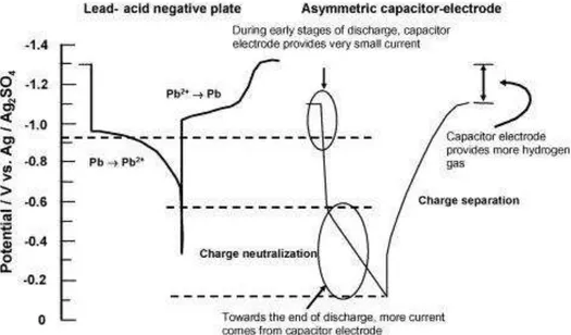
The main issue of the UltraBattery® is the different operational voltage of the two parts of its negative split electrode. For example, during the battery's discharge, the oxidation of lead to lead sulfate occurs at the potential of -0.98 V (SCE) on the LAB’s negative electrode, charge neutralization occurs at voltages of more than 0.5V (SHE), and charge separation occurs at -0.3V (SHE) during the battery's charge (Fig.5).67
Therefore, during discharge the current comes mainly from the lead-acid negative electrode with the smaller portion coming from the capacitor negative electrode, and this portion increases at the end of the discharge. However, the main current first comes to the negative capacitor electrode at the beginning of charge and then to the negative lead-acid electrode. This leads to the side hydrogen evolution reaction on the negative lead-acid electrode, and it could be reduced by adding hydrogen inhibitors to the carbon electrode to reduce the hydrogen evolution reaction (HER) on it to the level of HER on the negative lead-acid electrode.
14
Figure 5: Operational potentials of a lead-acid negative plate and a carbon-based capacitor electrode during discharge and charge.67
Thus, the UB's innovative design and architecture give it a more advanced performance (cycle life, charge acceptance, cost efficiency) than LABs, NiMH batteries, and LIBs. The charge/discharge characteristics of the UB compared with the traditional LAB are shown in Figure 6. The UB capacity was improved by decreasing sulfation (formation on non-conductive film of PbSO4) of NEs and blocking the active surface of NEs. The capacitor included in the UB is intended to increase the power and lifespan of LABs as it plays a buffering role during high rate of charge or discharge events. Examples of this are when the capacitor provides or absorbs charge quickly during hybrid electric vehicle acceleration and regenerative braking manoeuvres. UltraBattery® provides the following significant advantages:
Performance combining fast charge from the supercapacitor technology with the concentrated energy of a lead-acid battery
Longer cycle life (tens of thousands to millions of PSoC cycles depending on the cycle range of charge)
High performance and efficiency for both power and energy applications Faster charging
Advanced performance for UB-based HEV with a driving mileage of 100,000 miles/charge
15 Figure 6: History of lead-acid battery technology68
In reviewing patent literature, CSIRO has claimed several designs of negative electrode for UB’s, including the deposition of NE and ASC electrode pastes on opposite sides of Pb foam (electrode current collector), and the deposition of two layers of NE and ASC electrode pastes on one side of Pb foam , and only NE paste on the other side of Pb foam. 67
The capacitor electrode consists of 20% carbon black with the specific surface area of 60 m2/g (Denki Kagaku, Japan), binder (7.5% carboxymethyl cellulose + 7.5% neoprene), and 65% activated carbon with the specific surface area of 2000 m2/g (Kuraray Kemikaru Co. Ltd, Japan).67The LAB's lead-containing paste (NAM) comprises leady oxide -1000g (83.7wt%), fiber 0.6 g (5wt %), carbon black -0.26 g (2.1wt%), BaSO4 - 4.93 g, H2SO4 (1.4g/cm3) - 80g, and water -110 ml; 4% sulfuric acid to leady oxide ratio, and paste density 4.2 g/cm3.66,67 The leady oxide was converted into lead oxide (PbO2) and lead (Pb) during formation of NEs. The UB's main benefits are the long cycle life and higher capacity turnover under cycling operations at PSoC.
Longevity Tests
There are two main types of longevity tests for UBs for applications with low (each cycle lasts for some minutes with small DOD) and high rates compared to 1C rate. The high rate test represents “balancing applications”, such as HEVs and renewable energy smoothing. Low rate tests are mainly related to energy storage applications. A battery usually reaches the end of its life at the reduction of its capacity to 70-80% of its nominal life. The UB exceeds
16
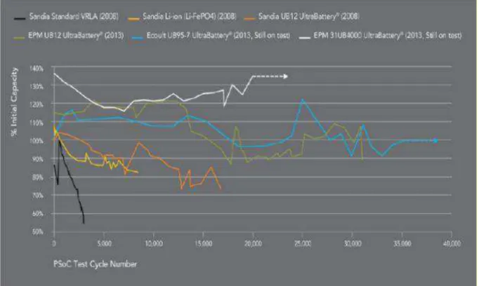
the cycle life of traditional lead-acid batteries (Figure 7)68 and Li-ion batteries (Fig.8).73 The UB's cycle life is seven times longer (the cycle life of 5000 full capacity tests) than that of the AGM VRLAB after cycling at 1C, remaining at 100% of initial capacity (the VRLAB’s capacity decreased 80% after 2500 cycles) (Figure 7). The UB has a better cycle life than the Li-ion battery.
The sustainability of UB for hybrid electric vehicles was demonstrated in an HEV Honda Civic with the UB pack providing a driving range of 160,000 km/charge. The laboratory test of UB in simulated conditions of the operation of medium-HEV at 60% SOC demonstrates the cycle life of 40,000 cycles that is 10 times longer than that of a conventional LAB.68UB has several advantages compared with the main NiMH battery:
70% less expensive Faster charge/discharge High Efficiency
UB has the typical DC-DC efficiency of 93-95% at its usage in regulation services applications. (Figure.9). The main applications of the UltraBattery® technology are as follows:68
Micro- and medium-HEV hybrid electric vehicles (Honda Civic HEV-100,000 miles/charge)
Figure 7: Discharge voltage as a function of the number of cycles (EUCAR cycle life test at SOC and 2hr capacity
17
Figure 8: Longevity test of VRLA battery, Li-Ion battery, and UltraBattery for regulation service application PSoC68
Battery energy storage with high power output capability for railways (electricity distribution network operating in parallel with grid supplying)
Energy storage technology in smart grids (i.e.: for smoothing wind farm output) Utility cycling applications (for PSoC cycling at different rates 1C to 4C)
The main benefits of UltraBattery® compared to lead-acid batteries are as follows: Lower life cost per kWh
Better charge acceptance (quicker recharging) Lower maintenance
18
Figure 9: Efficiency (Wh) of UltraBattery PSoC and different C rates 0.1C, 0.2C, 0.4C Discharge at 0.6C, 10A. Charge at: 0.45C, 10C.68
19
3
DEVELOPMENT OF DESIGN AND MATERIALS FOR
ASYMMETRIC SUPERCAPACITORS (ASC)
3.1
Baseline System Selection of Supercapacitor
The determination of a baseline supercapacitor cell is critical for assessing its commercially available components, which will ensure the supercapacitor's functionality as part of hybrid battery negative electrodes in the next phase. It was decided that the baseline cell would be a carbon-based supercapacitor, as this is the main type of supercapacitor found in the market.
Conventional components of a supercapacitor were then determined, purchased, and shared among the phases. These include:
Stainless steel or lead foil current collectors
Microporous Teflon sheets from W. L. Gore as separators YP80 carbon from Kuraray as activated carbon
Super C45 from Timcal Canada as the conducting carbon additive of the active layer The formulation of the active layers paste is of prime importance for the reproducibility of the results. The activated carbons used to store the energy are generally not good electrical conductors, which limits the power output of the system. A selected amount of conductive carbon (carbon black, graphite, or more recently, carbon nanotubes) is thus mixed with the activated carbon to increase the conductivity, and avoid this limitation. A number of companies in the lithium-ion industry use a polyvinylidene fluoride (PVDF) binder to turn the active material powders into a paste and bind them to the current collectors. However, the use of an important quantity of PVDF is required to ensure good mechanical properties (10-15 wt%). PTFE is also used as a binder in the industry. It has the ability to bind the powders very efficiently, even at very low content (typically 5 wt%). Because of its higher performance long-term, the PTFE binder was selected for this part of the study. As a baseline active material paste, it was chosen to use:
80 wt% of YP80 activated carbon
15 wt% of C45 carbon as conductive additive 5 wt% of PTFE binder
Two current collectors were chosen for the characterization baselines: 300µm in thickness of stainless steel (AISI 316)
700µm in thickness of the lead foil
The electrolyte 1.28 g/cm3 sulfuric acid used in the traditional lead-acid battery was chosen for the characterization baseline cells.
3.2
Supercapacitor Lab-Test Cell
An NRC home-made lab-test cell and an air-tight box were chosen for evaluation of the supercapacitor. Figure 10 shows several views of the NRC cell design.
20
Figure 10: Design of the supercapacitor laboratory test-cell a) expanded view and b) assembled cell in its beaker with two Teflon fillings (in green) designed to decrease the amount of electrolyte needed to fill the beaker
The cell was designed for a cell stack size of 2 cm x 2 cm. The cell stack (active material pastes + current collectors + separator) is assembled in a compartment carved in one face of the two Teflon plates (Figure 10a, left), and the size is 2.05 x 2.05 cm. At each corner of the compartment, a small hole has been carved for a suitable folding of the separator sheet (which has to be bigger than the compartment size to effectively prevent short-circuits). On the opposite Teflon plate (Figure 10a, right), a block 2 x 2 cm2 in size closes the stack compartment.
On the upper side of the stack compartment, two channels are carved for the electrical connections of the current collectors. The cylindrical compartment for the reference electrode is carved on the side of the stack compartment. A small channel at the bottom of this compartment connects the two compartments.
Figure 11 shows the test consisting of a) internal Teflon plates showing the compartment for the supercapacitor stack: current collectors, active materials and separator, as well as the reference electrode compartment, b) pressure system including two metallic plates with a three-point screwing design for an optimal pressure balance, as well as two metallic coins which effectively transfer the pressure to the internal cell compartment, and c) assembled cell showing the metallic current collector of each electrode protruding from the upper side and the reference electrode placed in its compartment.
21 Figure 11: Photographs of the laboratory test-cell
Two metallic plates are placed on each side of the assembled cell and are screwed using a three-point geometry ensuring a better pressure balance than a four-point geometry. The pressure from the metallic plates is directly transferred to the supercapacitor stack through two metallic coins placed on the back of each Teflon plate of the internal cell (Figure 11b). The test-cell was designed to allow the optional addition of a pressure sensor (Figure 10a). This will allow very precise control of the pressure applied to the cell with the screws, and refine the pressure application procedure. This will also allow the study of the variations of the stack pressure during cycling.
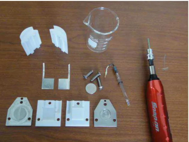
The complete set of components is show in Figure 12. The beaker volume is 100 mL, but two Teflon fillings (on the upper left corner of the Figure) have been designed to fill the volume not occupied by the cell (Figure 10b), in order to minimize the amount of electrolyte needed to ~ 20 ml.
22
Figure 12: Photograph of a disassembled cell showing all components including the beaker, Teflon fillings and a dynamometric screwdriver used to control the pressure applied to the internal cell
3.3
Integration of Carbon Electrodes into the Baseline
Supercapacitor and ASC
3.3.1
Preparation of the Baseline Active Layer Pastes and Electrodes
Different procedures can be found in the literature to turn the active material powders into a paste and bind them to the current collectors.Depending on the active material, conductivity additive, and binder used, the weight ratio of active material, additive and binder ranged from 90-80:5-15:5-15. In this study, Kuraray YP-80, Timcal Super C45 and PTFE were used to prepare electrode layers for the baseline test. The composition ratio used was 80:15:5. The paste was prepared as follows:
1. YP-80, C45, and PTFE were first weighted, mixed, and ground together in a mortar 2. The mixtures were then transferred to a beaker and dispersed in ethanol under strong
stirring
3. The PTFE binder was then added with more ethanol to the powder dispersion, and the temperature was raised to evaporate the solvent
23
4. After most of the ethanol had been removed, the paste was collected on a glass slide, where it was manipulated (mixed together) with a spatula to impart some mechanical cohesion
5. When sufficient mechanical properties were obtained from the wet paste, it was submitted to several cycles of rolling and folding to homogeneously disperse the PTFE fibrils in the paste
6. Cycles of drying in air and rewetting with ethanol may be necessary while the paste is being manipulated, as ethanol makes the PTFE fibrillate
7. When sufficient mechanical properties were obtained from the active layer paste, it was rolled to the required various thicknesses (in this formulation study, three thicknesses were tried, i.e., 115 µm, 250 µm and 850 µm) using side gauges, as shown in Figure 2.4.
Squares (8.2 cm x 2 cm) of active materials were then cut in the paste and placed in an oven at 120°C under an active vacuum (Figure.13b) overnight, weighed, and transferred as electrodes for assembly.
Figure 13: Photographs of a) rolling press and b) vacuum oven
3.3.2
Preparation of the ASC Active Layer Pastes and Electrodes
Active materials for the ASC in a hybrid battery system are commonly requested to add additives to prevent hydrogen gassing due to the mismatch between the cell's voltage and the potential range of the electrode. The common additives for hydrogen inhibition in hybrid lead-acid batteries are oxides. In this formulation study, lead oxide was chosen. The active materials for the ASC negative electrode in this work consist of:
80 wt.% of YP80 activated carbon
10 wt.% of C45 carbon as conductive additive 5 wt.% of PTFE binder
24
One current collector was chosen for characterization of the ASC negative electrode: 300µm in thickness of stainless steel
The electrolyte medium was chosen for characterization of the ASC negative electrode: 1.28 g/cm3
sulfuric acid
Preparation of the ACS active layer pastes and electrodes was as described in part 3.3.1
3.3.3
Assembly of Baseline Supercapacitor and ASC Lab-Test Cell
Proper assembly of the test cell was of great importance in order to ensure reproducible results. The parameters found to be critical are impregnation of the electrolyte by the active layer paste and the pressure applied to the cell.
Two electrodes (2 x 2 cm), made as in sections 3.3.1 and 3.2.3.2, and the separator were first aligned and laminated together, then dried in a vacuum oven at 80ºC for 6 hours. The sandwiched electrode and separator were then impregnated with electrolyte under vacuum before being assembled into a test cell. A few drops of electrolyte were added at each step of the test cell’s assembly in order to ensure the presence of a proper amount of electrolyte in the core of the cell.
Control of the pressure is very important to reproducible results from the cells, thus pressure was applied to the test cell using a dynamometric screwdriver at torque 200cNm for the pressure screws to intimately bind the different layers of the stack. Figure 11c represents the assembled cell showing the metallic current collector of each electrode protruding from the upper side and the reference electrode placed in its compartment.
3.4
Electrochemical Test of Baseline Supercapacitor and ASC
Assessment of the baseline supercapacitor and carbon-based ASC performances is achieved using different techniques of electrochemical characterization.
A specific procedure was determined, including the following techniques: Cyclic voltammetry
Galvanostatic cycling
These procedures allow for the determination of the main characteristics of supercapacitor and ASC: capacitance of the active materials, maximum voltage, and cyclability.
Cyclic voltammetry (CV) is one of the key techniques used for the electrochemical characterization of energy storage devices. The voltage (or potential, when looking at a single electrode) is progressively scanned back and forth at a constant rate between two limits, and the current response is recorded.
In galvanostatic experiments, a constant current is applied to the cells and the voltage response is baseline recorded.