An Architecture Synthesis System for Embedded
Processors
by
George Ioannou Hadjiyiannis
S.M. (EECS) Massachusetts Institute of Technology (Sep. 1995)
B.S. (EECS) Massachusetts Institute of Technology (Sep. 1993)
Submitted to the Department of Electrical Engineering and Computer
Science
in partial fulfillment of the requirements for the degree of
Doctor of Philosophy
at the
MASSACHUSETTS INSTITUTE OF TECHNOLOGY
June 2000
©
Massachusetts Institute of Technology 2000. All rights reserved.
Author .. Department o ... a ...
Departmen~t o
ectrical Engineering
and Computer Science
May 3, 2000
C ertified by ...
.
...
Srinivas Devadas
Professor
Thesis Supervisor
Accepted by ...
Chairman,
Arthur C. Smith
Department Committee on Graduate Students
MASSACHUSETTS INSTITUTE OF TECHNOLOGY
JUN
An Architecture Synthesis System for Embedded Processors
by
George Ioannou Hadjiyiannis
Submitted to the Department of Electrical Engineering and Computer Science on May 3, 2000, in partial fulfillment of the
requirements for the degree of Doctor of Philosophy
Abstract
Design requirements for embedded systems call for architectures with small size, low power consumption and low cost. These requirements can be met by designing cus-tom architectures for every single application. However, the commercial viability of embedded systems calls for short design cycles. These requirements are conflicting: custom architectures take a long time and substantial effort to produce, because of the need to manually generate design evaluation tools, such as simulators and compilers, for each architecture candidate. This conflict can be eliminated by providing a system capable of generating all design evaluation tools for a given candidate architecture.
This thesis presents two components of the ARIES environment for architecture synthesis: the machine description language ISDL and the GENSIM simulator gener-ator system. We also briefly describe the HGEN hardware model genergener-ator. In the ARIES system, candidate architectures are described in the ISDL language. From this machine description, component tools can automatically generate design evaluation tools, namely an assembler, Instruction Level Simulator, and disassembler. These tools can be used to evaluate each candidate architecture and make improvements. The whole process can be used to implement an architecture exploration loop which provides the benefits of custom architectures while maintaining short design cycles. Preliminary results also show that it is possible to generate retargetable compilers and hardware models from the same machine description.
ISDL is a flexible machine description language that supports a wide range of ar-chitectures and features with special emphasis on VLIW arar-chitectures. It provides sufficient information to generate all the tools from a single machine description, and provides constraints which make the machine descriptions concise and intuitive. The GENSIM simulator generator is a tool that can automatically produce fast (4.5 Mops), cycle-accurate, bit-true Instruction Level Simulators from ISDL descriptions in a short time. We present experimental results which show that ISDL is flexible enough to describe a wide range of architectures implementing a broad range of ar-chitectural features. We also present experimental results demonstrating the capabil-ities of the GENSIM system and the generated simulators. Finally we present results that demonstrate the feasibility of architecture exploration based on automatically
generated design evaluation tools. Thesis Supervisor: Srinivas Devadas Title: Professor
Acknowledgments
During the five years that I have worked on the ARIES project and the research described in this document, a number of people stepped forth to provide their con-tributions to either my work or my life and support this task directly or indirectly. These are the people that I wish to thank for supporting me in my endeavors, both in my academic and my personal life.
First of all I would like to thank my Thesis Supervisor, Prof. Srinivas Devadas. Prof. Devadas undertook the demanding role of attempting to guide me through my work, providing both academic help with the nature of the problems I encountered, as well as help in the direction and the manner in which I performed my work. He has always made himself available, and always did his best to help, even when - on occasion - I made it hard for him to do so. He has always shown the enthusiasm of a child and the wisdom of experience in everything that we did together. I must say I thoroughly enjoyed all the time I spent working with him. I was also fortunate enough to have enjoyed a relationship of friendship with Prof. Devadas which made it even easier and more enjoyable to work with him. He takes a personal interest in the lives of his students and I hope that he realizes that all his students appreciate it.
I would also like to thank my colleagues, Silvina Hanono, and Daniel Engels. Silvina's help in developing ISDL was invaluable. I truly believe that without it the project would have suffered dramatically. She also provided help with almost all other aspects of my work, from co-authoring and proof-reading papers, to helping with coding problems. Dan has always provided a sounding board for all my ideas and provided endless help with papers and algorithms. Both Silvina and Dan where kind enough to let me know when I was heading down the wrong path and to persist until I saw it, thus saving me an incalculable amount of wasted effort.
I would also like to thank a number of friends who supported me on a more personal level: Mike Ehrlich, Sabine Bendiek, Jennifer Trickett, Radu Rugina and Maria Marinescu. Their support has always made it possible for me to maintain my motivation and their judgment has always forced me to do things the right way.
Last, but definitely not least, I would like to thank my parents for setting me on this path at a very young age and never letting me stray from it. While they have never judged the manner in which I conducted myself with regard to my studies and my work, they instilled in me the courage to judge myself. They taught me the value of education and left it up to me to seek it for my own benefit. And for years they struggled to provide me with any resource and any chance I needed to get to where I am today.
Contents
1 Introduction 11
1.1 Introduction . . . . 11
1.1.1 Hardware/Software Co-Design . . . . 11
1.1.2 Embedded Processor Requirements . . . . 12
1.2 Architecture Synthesis for Embedded Systems . . . . 13
1.2.1 Overview of Architecture Exploration by Iterative Improvement 14 1.2.2 Architecture Exploration for Embedded Systems . . . . 14
1.2.3 Requirements for Architecture Exploration . . . . 15
1.2.4 Overview of the ARIES System . . . . 16
1.3 Contributions . . . . 19
1.3.1 ISD L . . . . 20
1.3.2 Simulator and Hardware Model Generation . . . . 20
2 Instruction Set Description Language (ISDL) 21 2.1 Requirements and Features . . . . 21
2.1.1 Specifying a Wide Variety Of Architectures . . . . 23
2.1.2 ISDL Descriptions as a Programmer's Manual . . . . 23
2.2 Syntax and Semantics of ISDL . . . . 24
2.2.1 Instruction Word Format . . . . 24
2.2.2 Global Definitions . . . . 25
2.2.3 Storage Resources . . . . 26
2.2.4 Instruction Set . . . . 27
2.2.5 Constraints . . . . 29
2.2.6 Optional Architectural Details . . . . 31
2.2.7 Macro Definitions . . . . 31
2.2.8 ISDL Model of the Instruction Set . . . . 31
2.3 An Extended ISDL Example . . . . 33
2.4 Describing Real-world Architectures . . . . 38
2.4.1 Time-Shifted Constraints . . . . 38
2.4.2 Register Aliasing . . . . 38
2.4.3 Heavy Op-code Encoding . . . . 39
2.4.4 Field Opcode Takeover . . . . 39
2.5 Related Work on Machine Description Languages for Embedded Pro-cessors . . . . 40
2.5.2 2.5.3
2.5.4
2.5.5
2.5.62.5.7
2.5.8FLEXWARE, CODESYN, and INSULIN ... ...
CHESS and nML . . . .
L ISA . . . . R A D L . . . . H M D ES . . . .
Other Machine Description Languages . . . . Using Constraints to Simplify the Machine Description
3 Simulator and Hardware Model Generation
3.1
Introduction . . . .
3.1.1 Requirements and Features . . . .
3.1.2
Simulator Structure. . . . .
3.1.3
Relationship Between Simulator and Hardware Model
3.2 The GENSIM Simulator Generator . . . . 3.2.1 Storage Generation . . . . 3.2.2 Disassembler Generation . . . . 3.2.3 Processing Core Generation . . . . 3.2.4 Restrictions . . . . 3.3 Hardware Model Generation . . . . 3.3.1 Module Library Approach . . . . 3.3.2 Hardware Synthesis from ISDL . . . . 3.3.3 Generating Decode Logic . . . . 3.4 Previous Work on Simulator and Hardware Model Generation
3.4.1 L ISA . . . . 3.4.2 R A DL . . . . 3.4.3 PLAYDOH . . . . 3.4.4 CHESS/nML. . . . . 3.4.5 M IM OLA . . . . 3.4.6 FLEXWARE . . . . 3.4.7 UPFAST/ADL . . . . 3.4.8 TRS-based Systems . . . .
4 Results
4.1 Experimental Results on ISDL Descriptions . . . . 4.2 Experimental Results on Simulator Generator . . . . 4.3 Experimental Results on Architecture Exploration . . . . 4.3.1 Experiments Regarding Data Processing . . . . 4.3.2 Experiments Regarding Control Flow . . . . 4.3.3 Overview of Architecture Exploration Results . . . .
5 Conclusions
5.1
Conclusions . . . .
5.2
Future Work . . . .
5.2.1
ISDL Version 2.x . . . .
5.2.2
Automated Architecture Synthesis
. . . .
40 41 41 42 42 42 43 45 45 45 47 48 49 50 50 64 66 69 69 71 74 74 74 75 75 75 76 76 76
77
78
78
8286
86
93
100
103
103
106
106
111A Glossary Of Terms
B BNF Syntax of ISDL
C Example Descriptions
C.1 The SPAM VLIW-1 Architecture ...
C.2 The SPAM VLIW-2 Architecture ...
C.3 The SPAM RISC Architecture ...
C.4 The Motorola 56000 DSP
. . . .
141. . . .
141
. . . .
150
. . . .
174
. . . .
183
D Example Applications
D.l Applications for the SPAM VLIW-1 Architecture . . . .
D.1.1 Finite Impulse Response (FIR) Filter . . . .
D.1.2 Infinite Impulse Response (IIR) Filter . . . .
D.2 Applications for the SPAM VLIW-2 Architecture . . . .
D.2.1 Finite Impulse Response (FIR) Filter . . . .
D.2.2 Infinite Impulse Response (1IR) Filter . . . .
D.3 Applications for the SPAM RISC Architecture . . . .
D.3.1
Divide-and- Conquer Array Accumulate Function.
235
235
235 240 245 245 252 259 259117
132List of Figures
1-1
A System-on-a-Chip ...
12
1-2 A Generic Hardware/Software Co-design Methodology . ... 13
1-3
Architecture Exploration by Iterative Improvement ...
14
1-4 The ARIES Framework ...
17
1-5
The ARIES Methodology ...
...
18
2-1 ISDL and Generated Tools ...
...
22
2-2 ISDL M odel of Instructions ...
32
2-3 The SPAM VLIW-1 Architecture ...
33
2-4 The Instruction Word of the SPAM VLIW-1 Architecture. .
33
2-5 Constraints Help to Simplify the Machine Description . . .. 433-1
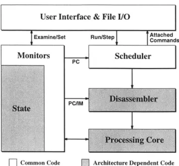
Internal Structure of the XsIM Simulator ...
47
3-2 Model of the Assembly Function in ISDL ... ... 51
3-3
Assembly Function Modified for Reversal ...
52
3-4 Generating the Decode BDD BD ... --... .. 53
3-5
Disassembly Using Decode BDD
BD ...-...54
3-6
Annotating Operations and Non-terminal Options with
Sig-natures . . . .
57
3-7
Example of Signature Annotation ...
58
3-8
Example of the Forward/Backward Pass Algorithm . . . .
63
3-9
Disassembly Algorithm . . . .
65
3-10 Implementation Based on Module Libraries ...
69
3-11 Hardware Synthesis from ISDL ... . 71
3-12 Resource Sharing Algorithm ...
73
3-13 Use of Signatures and Op-Codes for Decode Logic ...
74
4-1
The SPAM VLIW-1 Architecture ...
78
4-2 The SPAM VLIW-2 Architecture ...
79
4-3 The SPAM RISC Architecture ...
80
4-4 The Motorola 56000 Architecture ...
81
4-5 Part of the 8-Tap FIR for the SPAM VLIW-1 Version a
. .
.
87
4-6 Modifications to Derive SPAM VLIW-1 Version b ...
88
4-7 Part of the 8-TAP FIR for the SPAM VLIW-1 Version b
.
.
89
4-8 Modifications to Derive SPAM VLIW-1 Version c ...
90
4-10
Modifications to Derive SPAM VLIW-2 Version b ...
92
4-11
Part of the 8-TAP FIR for the SPAM VLIW-2 Version b
.
.
93
4-12
Modifications to Derive SPAM VLIW-2 Version c ...
94
4-13 The Array-Accumulate Divide-and-Conquer Algorithm . ... 94
4-14
Assembly Implementation of the Array-Accumulate Function
96
4-15
The Stack Frame for the
acc
Function ...
97
4-16
The New Addressing Modes of SPAM RISC Version b
. . .
.
97
4-17 Array Accumulate Function for SPAM RISC Version b . . . 98
4-18
Adjusted Operations of SPAM RISC Version c ...
99
4-19
Pipeline Flushing in SPAM RISC Version d ...
99
4-20
Delay Slots in SPAM RISC Version e ...
100
4-21 Array Accumulate Function for SPAM RISC Version e . . .. 101
C-1 The SPAM VLIW-1 Architecture. ...
141
C-2 The SPAM VLIW-2 Architecture. ...
150
C-3 The SPAM RISC Architecture. ...
174
List of Tables
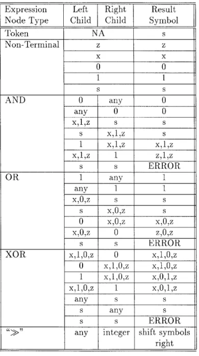
3.1
Composition Rules for Signatures . . . .
56
3.2
Merging Rules for Signatures . . . .
58
4.1
Summary of ISDL Descriptions of Base Architectures ...
80
4.2
Architectures Used for Simulator Generation . . . .
83
4.3
Simulator Generation Speed Results . . . .
84
4.4
Simulation Speed Results . . . .
85
4.5
Results of Architecture Exploration on SPAM VLIW-1
. ..
90
4.6
Results of Architecture Exploration on SPAM VLIW-2
. ..
94
4.7
Results of Architecture Exploration on SPAM RISC . . . . .
102
Chapter 1
Introduction
1.1
Introduction
In recent years there has been an tremendous growth in the use of consumer electronic products such as personal digital assistants, multi-media systems, and cellular phones. The digital circuits that control and process data in these devices are called embedded systems. If these systems contain programmable processors, these are referred to as
embedded processors.
Architecture design for embedded processors is substantially different from archi-tecture design for general-purpose processors. The latter strives to create processors of maximum possible performance for a given cost. Additionally, because of their general nature, the domains in which these processors are applied often overlap sub-stantially, and as a result not many designs exist and most of them share a lot of features. Finally, the applications that these processors will be called upon to run are not known at design time, and therefore the processors cannot be customized to any specific application. By contrast, the world of embedded processors contains a much richer set of designs and covers a substantially larger portion of the architec-ture design space. Furthermore, the applications that embedded processors are called upon to execute are known at design time so theoretically each processor could be customized for the particular application it will be used for. This results in complex architectures containing a variety of custom architectural features.
This document is concerned with the task of producing architectures for embedded processors.
1.1.1
Hardware/Software Co-Design
To reduce the cost, size, and power consumption of embedded systems, manufacturers often integrate an entire system on a single integrated circuit (IC) [11, 5]. In addi-tion, the pressure for short design cycles forces designers to implement an increasing amount of functionality in software relative to hardware. The software implementa-tions can accommodate late changes in the requirements or design, thus reducing the length of the design cycle. Figure 1-1 illustrates a typical embedded system, consist-ing of a digital signal processor (DSP) core or an application-specific instruction-set
DSP Program Core ROM or ASIP RAM ASIC Figure 1-1: A System-on-a-Chip
processor (ASIP), a program ROM, RAM, application-specific circuitry (ASIC), and peripheral circuitry.
Since the embedded processor, the program ROM and the custom ASIC are im-plemented on the same chip, the hardware and software components of embedded systems are strongly coupled. Small changes in the hardware (software) can affect the software (hardware) dramatically. In order to address the interaction between the hardware and software, a hardware-software co-design methodology (e.g., [12]) is required.
A simplified view of a generic hardware-software co-design methodology is shown in Figure 1-2. In this design methodology, designers partition the system function-ality (i.e., input application) into hardware and software components. Additionally, a target processor is chosen from existing processor designs, or an ASIP is designed to execute the software. The hardware, software, and ASIP are implemented, and the resulting system is evaluated using a hardware-software co-simulator. The par-titioning and processor design are repeated until an acceptable system is developed. This document focuses on the software synthesis portion of hardware-software co-design. Software synthesis involves designing a target processor to execute the soft-ware component of the embedded system, and compiling the softsoft-ware component of the application for the target processor.
1.1.2
Embedded Processor Requirements
Because most embedded processors are used in consumer electronics, their commercial success requires low-cost architectures. Most applications (e.g., cellular phones) also have stringent requirements on size and power consumption for the sake of portability. Additionally, embedded processors are designed with a particular performance target in mind. In most cases, creating a processor that can provide more that the target performance does not provide any advantage. Finally, the commercial success of such products requires short time-to-market and therefore short design cycles.
Design Hardware-Software
Partitioning
Hardware Synthesis Software Syoesio . ASIC Design . Target architecture
model
.Custom datapath .dgenerati oa
a substantil amount o time and ffort.CThi
ei
beaus nmerocnidtHardware-Software
Co-Simulation
System
Ea atvaluation
Figure 1-2: A Generic Hardware/ Software Co-design Methodology
In order to produce embedded systems which satisfy, cost, power consumption and size requirements, it is desirable to customize the architecture of embedded processors
to the application at hand. However, generating a custom architecture often involves
a substantial amount of time and effort. This is because a number of candidate architectures must be designed, evaluated, and successively refined before a final architecture is selected. For every candidate architecture, a set of design evaluation tools
(such
as compiler, assembler, simulator, and hardware model) must be created, resulting in substantial development effort and long design cycles. This results in conflicting requirements.1.2
Architecture Synthesis for Embedded Systems
One way of performing architecture selection is to explore the architectural design space until a suitable design is found. To implement such a search, an initial archi-tecture is created and evaluated in the context of the application at hand. Possible improvements are located and implemented resulting in a new architecture. This architecture is once again evaluated and the process repeated until no further im-provement can be obtained. This process is called architecture exploration by iterative improvement.In order for architecture exploration to cover a large portion of the design space, the design evaluation tools
(i.e.,
assembler, disassembler, compiler, simulator, and hardware model) must be either automatically retargeted or generated for each can-didate architecture.Physical Design &
Source Hardware Cycle Length ASIP
Code Model Generation Pr e (C)Pefrac
Statistics/ Evaluation Machine Description
(ISDL)
Retargetable Retargetable Retargetable Compiler Assembly Assembler Binary Simulator
Figure 1-3: Architecture Exploration by Iterative Improvement
1.2.1
Overview of Architecture Exploration by Iterative
Im-provement
Figure 1-3 shows a fully automated system based on architecture exploration. In this approach, the application code is analyzed, and an initial architecture is gener-ated and described using a machine description language. This machine description is then fed into a retargetable compiler along with the application source code. The retargetable compiler translates the source code into assembly code for the target processor, optimized for speed and code size. The same machine description is also passed to a retargetable assembler that converts the assembly code into binary code for the target processor. Next, a retargetable simulator receives the machine descrip-tion and the binary code as inputs and executes the code. The simulator generates a set of measurements that can be used to evaluate the architecture and identify possible improvements. The machine description is also used to generate a hardware model of the processor that provides the physical costs of the design (i.e., die size, cycle length, and power consumption). If the performance of the processor does not satisfy the design specifications, or if the cost, size, or power consumption can be re-duced without sacrificing performance, then the appropriate changes are made to the processor architecture and a new machine description is generated. The entire design process is repeated using the new machine description until no further improvements can be made. Once the final architecture has been determined, the hardware model can be used to generate an implementation of the architecture.
1.2.2
Architecture Exploration for Embedded Systems
Section 1.2.1 describes a completely automated architecture exploration system. How-ever, for the domain of embedded DSP applications not all the tasks have to be au-tomated. In embedded DSP applications only a small portion of the code is critical to performance, and this is typically implemented as hand-coded assembly libraries. These libraries contain code commonly used in DSP applications such as Finite Im-pulse Response (FIR) and Infinite ImIm-pulse Response (1IR) filters, Fast Fourier
form (FFT) functions, and so on. Most of the time taken for DSP applications is consumed by such functions for almost all DSP applications.
Given that the set of tasks that require good performance is small and well-known it is possible to implement these libraries by hand-coded assembly for every iteration of the loop. Note that this does not mean that an architecture optimized for these libraries is the optimal architecture for any application that uses them. The code that will form the bottleneck in performance is indeed in these libraries, however, the code that will incur the most significant code-size cost is the remainder1. Additionally,
size and power consumption still need to be optimized, and the tradeoffs may be such that the optimal point is not the same for every application. Consider for example, an application where an FIR is used to filter a low quality audio channel. The typical sample rate for such applications is 8KHz, thus performance may not be a big concern and instead code size and power consumption might become the dominant factors in architecture selection. If instead the FIR filter is to be used in a high-speed military radar system where sample rates of MHz are not uncommon, performance will be the primary concern in architecture selection since it is the hardest constraint to meet.
Given that for embedded applications small amounts of highly optimized code are typical, it is possible to perform architecture exploration without having some of the design evaluation tools. For example, a compiler is not necessary since the amount of code that has to be optimized is small. It is possible to hand-code assembly for each iteration of the architecture exploration for the particular application. Additionally, a hardware model may not be necessary if the designer is familiar with the physical properties of various architectural features. Finally, the fact that most of the code is not performance critical and the code that is performance critical is small decouples issues of code-size from performance allowing a manual architecture exploration loop supported simply by an Instruction Level Simulator and an assembler. In this process, a designer generates an initial architecture based on intuition and experience with typical applications in the DSP domain. She then describes the architecture in a machine description language and uses this description to generate an assembler and an instruction level simulator. She codes in assembly the time-critical portions of the application and simulates them to get performance measurements. She modifies the architecture, generates another description, and repeats the loop until she is satisfied that no more improvements can be made. Then, she codes the rest of the application in hand-coded assembly and repeats the process trying to minimize code size without degrading performance.
1.2.3
Requirements for Architecture Exploration
For architecture exploration to be successful, any implementation of it must provide the following:
* A system that can automatically produce design evaluation tools given a de-scription of a target architecture. For a fully automated process all the design
'This is a result of the well-known 80/20 rule: 80% of the time is spent on 20% of the code. The corollarly to the rule is that 80% of the code size is incurred by code that is not performance critical.
evaluation tools must be produced automatically. If a single tool has to be developed manually, then the effort and time required for a single iteration of the architecture exploration algorithm will be dominated by the effort and time to develop that tool. The required evaluation tools are: an assembler, a dis-assembler, an optimizing compiler, an Instruction Level Simulator (ILS), and a hardware model. For a partly automated process, such as the one described in Section 1.2.2, an assembler and instruction level simulator are necessary. A hardware model would be beneficial if provided but not critical.
* A machine description language which can describe as wide a variety of archi-tectures as possible at a fine granularity. This language should provide features that support the generation of all required design evaluation tools from a single machine description. This avoids possible problems of consistency and the effort of translating machine descriptions between different languages.
* A way of extracting useful information from the design evaluation tools to iden-tify possible improvements to the architecture.
1.2.4
Overview of the ARIES System
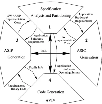
The work presented in this document was performed in the context of the ARIES system. The ARIES system is our planned implementation of a Hardware/Software Co-Design system implementing architecture exploration by iterative improvement. Figure 1-4 shows the framework of the system.
The main components of the ARIES system are:
* A top-level application analysis and partitioning tool that performs the parti-tioning between hardware and software.
* An ASIC generation tool which implements the hardware component.
* An ASIP tool which implements and evaluates candidate architectures for the embedded processor.
e The Aviv code generator tool which generates retargetable compilers and as-semblers for a candidate architecture given a machine description.
* The ISDL machine description language which describes the candidate architec-ture to the necessary components.
The ASIP generation tool, Aviv code generator, and ISDL machine description language implement the architecture exploration portion of ARIES.
Figure 1-5 shows the methodology of the ARIES system. A description of the application in a high-level language is provided as a system specification. This forms the input to the analysis and partitioning tool which partitions the specification into hardware and software components. The hardware component is passed to an ASIC
Specification
SW / ASIP Analysis and Partitioning
HApplication
Implementation Hrduree/
Costs Rqieet
Application HW
3
Reftwarets Implementation2
ReeuiirentenCost
ASIP ISDL ASIC
Binar Code
Generation Generation
Profile Info ApplicationSoftware/ Operating Systemrati t
4
Requirements/
the ASIC. Fnally, thenartitonigtodasstheotaecmonnoteCd
ceal ComerCode Generation AVIV
Figure 1-4: The ARIES Framework
Synthesis tool which produces an HDL model in synthesizable Verilog. The parti-tioning tool also produces an interface specification which is passed to the Interface Synthesis tool. This tool implements theinoeae in HDL and also creates software stubs which are used by the Operating System Generation tool to communicate with the ASIC. Finally, the partitioning tool passes the software component to the Code Synthesis tool which produces specifications for the operating system and source code for the retargetable compiler. Finally, the partitioning tool provides a set of area, power, and performe and recometed constraints to the ASIP generation tool, which produces an initial architecture and describes it in ISDL. This machine description and the source code are used by the AVV retargetable compiler to pro-duce an implementation of the software component on the target architecture. It is also used to create an Instruction Level Simulator and a hardware model. The ILS and hardware model are used to evaluate the candidate architecture and recommend improvements resulting in a new architecture description. The loop is repeated until no further improvements can be made. The final hardware model is linked with the ASIC and interface models and the complete system is evaluated. Improvements are made by re-partitioning and re-iterating through the whole procedure.
This document focuses on the ASIP generation process and in particular, the ISDL machine description language[19, 15, 17, 14], the ILS generator (called GENSIM)[16, 18] and the hardware model generator (called HGEN)[16, 18]. Most of the compo-nents of the ARIES system have not been fully implemented yet. In particular, the
System Specification
Analysis/Partitioning
Requirements/
Constraints Constrints Software!Application OS requirements Code
2
Synthesis ISDL OS Generat OS source code ASIP ion Applica Source (C)t t
Retargetable Compiler (AVIV) Binary code tor Application Requirements Hardware Interface ASIC Synthesis Synthesis tion HDL HDL,ode model model
Interface stubs Technology mapping & Optimization System Simulation and Evaluation ASIC Hardware Performance Measurements
Figure 1-5: The ARIES Methodology
I
I
Costs & Performance StatisticsI
Iretargetable compiler is the most challenging task. Aviv was an attempt to provide some basic functionality for the retargetable compiler and investigate the issues in-volved in the design and implementation of such a compiler. While it has succeeded in those goals, it is still not a full-fledged compiler and cannot be used to automate the architecture exploration loop. The details of the Aviv retargetable compiler can be found in [20, 21]. Similarly, preliminary implementations of the partitioning tool exist, which where used to investigate the issues involved and the performance of some proposed algorithms. Again, however, these are the result of an incomplete implementation and cannot be used within an automated system. The details of the partitioning algorithm can be found in [6]. The results and conclusions presented in this document are therefore based on the partially automated approach of Section 1.2.2. Note, however, that the current implementation of ISDL and the simulator generator are complete and can be used within a fully automated system once full implementations of the remaining tools are provided.
1.3
Contributions
The work described in this document is based on the following thesis:
9 Architecture exploration by iterative improvement is an effective way of obtain-ing customized architectures for embedded systems.
* It is possible to obtain the advantages of a custom architecture while reducing design cycles by automating the generation of the design evaluation tools. e In order to support architecture exploration and automatically generated
eval-uation tools a flexible machine description language is necessary. This language should cover as much of the architecture design space as possible and support the automatic generation of at least an assembler, disassembler, and Instruction Level Simulator. Availability of tools that can generate a retargetable compiler and a hardware model will enable a fully automated architecture exploration loop. ISDL provides all the features necessary to describe a wide variety of archi-tectures and architectural features and contains enough information to generate all of the above tools.
* It is possible to generate fast, cycle-accurate and bit-true simulators, and effi-cient hardware models form ISDL. These simulators and hardware models are effective tools in evaluating candidate architectures.
The main goal of this document is to present the ISDL machine description lan-guage and the GENSIM simulator and HGEN hardware model generation systems, and provide experimental results supporting the above thesis.
1.3.1
ISDL
We present the ISDL machine description language for architecture exploration. ISDL has proven to be well-suited to the task of supporting architecture exploration. It can describe a wide range of architectures including VLIW, RISC, CISC, DSP and micro-controller processors and supports features as varied as register aliases, complex instructions and predicated execution. It supports the automatic generation of all design evaluation tools from a single machine description. It is easy to read, write and modify ISDL descriptions manually, and easy to produce them automatically. By providing constraints, ISDL allows for concise and intuitive descriptions of real-world architectures. ISDL modifications resulting in improvements can be performed in about an hour by an engineer skilled in the use of the language.
1.3.2
Simulator and Hardware Model Generation
We also present the GENSIM simulator generator and HGEN hardware model gen-erator. The GENSIM simulator generator is an implementation of an ILS generator based on ISDL. It processes machine descriptions in a reasonable amount of time, and produces simulators which are cycle-accurate to the instruction set level, and bit-true. The generated simulators are also fast, and provide full debugging support. Their ability to produce execution address traces means that dynamic counts for in-structions can be obtained which can be used to derive utilization statistics and thus point out possible improvements to the architecture. The GENSIM simulator gener-ator supports a wide variety of architectures and architectural features. The HGEN hardware generation model is a sister-tool based on the same algorithms implemented in GENSIM. It produces efficient hardware models of a candidate architecture given a machine description in ISDL. These models (implemented in synthesizable Verilog) can then be used to obtain the physical costs and parameters (such as cycle-length, die size, and power consumption) of the architecture.
Chapter 2
Instruction Set Description
Language (ISDL)
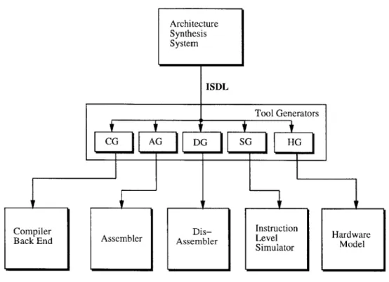
ISDL (Instruction Set Description Language) is a machine description language specif-ically designed to support retargetable tools for architecture exploration and develop-ment. In particular, it is designed to allow the automatic generation of an assembler, disassembler, code generator, instruction level simulator, and hardware model from a single description of the architecture. At the same time, it is designed to support architecture descriptions that are either generated automatically by another tool, or generated and/or modified manually by an engineer. Figure 2-1 shows how ISDL descriptions can be used to generate a set of tools to support a design environment.
ISDL supports the description of a wide variety of architectures. Its main fo-cus is on VLIW architectures; however, it also supports standard microcontrollers, and other unifunctional architectures. Unifunctional architectures can be considered degenerate cases of VLIW architectures. ISDL supports the description of multiple functional units, different interconnect topologies, complex instructions, resource con-flicts, pipelining idiosyncrasies, etc. ISDL can also describe automatically generated architectures. Such architectures cannot be guaranteed to have clean instruction sets (i.e., instruction sets where every operation combination is valid). In order to handle these instruction sets, ISDL supports explicit constraints that define the valid opera-tion groupings. This allows operaopera-tions in the instrucopera-tion set to be treated as if they are completely orthogonal. The compiler can then avoid generating invalid instruc-tions by ensuring that each instruction satisfies all of the constraints. Note that many commercial architectures also require such constraints (e.g., the Motorola 56000 DSP cannot perform a REPetition of a DO loop).
2.1
Requirements and Features
The machine description language is a critical component in the architecture explo-ration design flow and should be capable of performing the following functions:
* Specify a wide variety of architectures. In particular, it should support VLIW (Very Long Instruction Word) architectures because they are very efficient for
Architecture Synthesis System ISDL Tool Generators CG AG DG SG HG
Compiler Dis- Instruction Hardware
Back End Assembler Assembler Level Simulator Model
Figure 2-1: ISDL and Generated Tools
custom applications, and because more traditional architectures can be treated as degenerate cases of VLIW architectures.
e Explicitly support constraints that define valid instructions. e Be easily understandable and modifiable by a designer. 9 Support automatically retargetable code generation.
9 Support the automatic generation of an assembler, disassembler, compiler, In-struction Level Simulator and hardware model.
* Provide adequate information to allow for code optimizations.
* Decouple the description of an Instruction Set Architecture (ISA) from a par-ticular implementation of the ISA.
In order to ensure that all of the design evaluation tools receive a consistent ma-chine description, it is desirable that a single mama-chine description be used to retarget or generate all of the design evaluation tools. In addition, the effort of generating multiple machine descriptions for the different tools can be avoided by using a single machine description.
Various proposed machine description languages lack support for one or more of the above features (see Section 2.5 for a review). In contrast, ISDL provides all of the above features. We have written complete ISDL descriptions for ASIPs and
commercial DSP cores including a powerful seven-way VLIW ASIP and the Motorola
56000 DSP.
2.1.1
Specifying a Wide Variety Of Architectures
It is important that the range of architectures that are supported by the design en-vironment is not limited by the abilities of ISDL, but rather by the abilities of the various tools that handle ISDL descriptions and those that are generated from ISDL descriptions. In order to achieve this, ISDL attempts to encompass as wide a vari-ety of architectures as possible. In particular, ISDL supports Very Long Instruction Word (VLIW) architectures; these are not explicitly supported by most other machine description languages, and are a superset of more traditional architectures. VLIW ar-chitectures have more than one functional unit, and these functional units can be used in parallel. This parallelism is reflected in the instruction set, where instructions are groups of operations that can be performed in parallel'. One can consider the more traditional architectures that only have one unit active at any given time in their instruction set, (from now on called unifunctional architectures), to be degenerate cases of VLIW architectures.
VLIW architectures are very important for two reasons:
* By amortizing control overhead over a number of functional units they actually result in more efficient use of silicon area.
* Given that the set of VLIW architectures can be considered as a superset of the set of unifunctional architectures, then if we can describe VLIW architectures, we can automatically describe unifunctional architectures.
ISDL has specific features to support the efficient description of VLIW architec-tures. It can also gracefully handle unifunctional architecarchitec-tures. These two classes of architectures cover traditional micro-controllers, CISC and RISC processors, vector processors, most DSP cores, and a large number of Application Specific
Instruction-set Processors (ASIPs).
2.1.2
ISDL Descriptions as a Programmer's Manual
In order to make the task of understanding, writing and modifying ISDL descriptions easier, ISDL was designed to look like the conventional Programmer's Manual that accompanies most commercial processors and DSPs. It turns out that this also makes it easier to generate the support tools. In particular, ISDL models an architecture by describing the user visible state and then listing every operation that can affect this state. Thus, ISDL is a behavioral language (rather than a structural one). It does,
however, contain enough structural information to allow for the complete description
'This is in contrast to parallelism which is not apparent in the instruction set (such as the parallelism in super-scalar architectures).
of an architecture (although it tends to disguise such structural information in a behavioral-like fashion).
The 6 sections of an ISDL description correspond closely with the sections found in most Programmer's Manuals for commercial architectures. The Instruction Word Format describes how long the instruction word is, and how it can be broken down into subfields. Global Definitions correspond to the various data types and tables of common sub-expressions (such as addressing modes) common in most processors and DSPs. They are the main source of abstraction in ISDL. The Storage Resources section explicitly lists all the visible state of the processor2. The Instruction Set
section lists all possible operations that the architecture provides, grouped in fields. The effect of each operation on visible state, the assembly representation of the op-eration, the binary representation of the opop-eration, the timing characteristics of each operation, and various costs are all listed on a per-operation basis. The Constraints section describes various restrictions as to how these operations may be assembled into instruction words and programs. This corresponds to the restrictions commonly listed in the Programmer's Manual.
2.2
Syntax and Semantics
of
ISDL
An ISDL description consists of six sections:1. Instruction Word Format 2. Global Definitions
3. Storage Resources 4. Instruction Set 5. Constraints
6. Optional Architectural Details
ISDL also supports cpp style macros which allow common patterns to be easily reused.
Each of the sections listed above is described below, and a detailed example of each is provided in Section 2.3. There is also a BNF description of ISDL in Appendix B.
2.2.1
Instruction Word Format
The Instruction Word Format section defines the hardware instruction word. The instruction word is divided into one or more fields each containing one or more sub-fields. This section specifies the field and subfield division of the hardware instruction word. In particular, it specifies the ordering of the fields and subfields as well as the
bitwidth of each subfield. The instruction word is assembled by concatenating all of the subfields in the order specified, beginning with the most significant bit.
Note that the division into fields and subfields is a convenience to the designer. The subfield division may be arbitrary; however, careful subfield division can make later parts of the machine description easier to write.
2.2.2
Global Definitions
The second section of an ISDL description contains a list of definitions used in the later sections. These definitions form the main abstraction mechanism in ISDL. There are three types of global definitions in ISDL: Tokens, Non-terminals, and Split functions.
Tokens are a symbolic representation of the primitives in the assembly syntax of the target processor. Tokens are used to represent entities such as register names, memory bank names, and immediate constants. In addition, tokens can be used to group syntactically related entities such as the names of registers within a register file. In order to be able to differentiate among the elements in a group, tokens return a value identifying the particular element being represented (e.g., register names such as RO to R15 can be abbreviated as one token whose value corresponds to the register number). A token definition contains a name for the token, a definition of the assembly syntax for the syntactic entities it represents, and a return value if any.
Non-terminal and operation definitions can refer to tokens by their name.
In addition to the tokens explicitly listed in an ISDL machine description, there are additional tokens that are automatically defined (e.g., operation names). Further-more, ISDL also includes predefined tokens for integers, hexadecimals, floating point numbers, single characters, and labels (symbolic names that represent instruction memory locations).
Non-terminals are used to abstract common patterns in operation definitions (e.g., addressing modes). For example, consider a Move operation that moves data across a bus that has seven units attached to it:
Move SRC DEST
where SRC and DEST can each be one of seven different options. Without non-terminals, 49 rules are required to describe all possible syntax combinations. However, the source and destination could be factored out into non-terminals. This factoriza-tion would result in only three rules: one for the operafactoriza-tion, and one each for the SRC and DEST non-terminals.
Non-terminal definitions consist of a name followed by a list of options that the non-terminal can represent. Operation and other non-terminal definitions can refer to any non-terminal using its name3 . Non-terminal options consist of the following
components:
e
The assembly syntax of the option which can include references to tokens or other non-terminals." A return value that identifies the option. This value can be used in operation
bit-field assignments (Section 2.2.4). The return value of tokens and non-terminals referred to in the assembly syntax of the option can be used to define the return value for the option.
" An RTL action clause that describes the RTL equivalent of the option when the non-terminal is used in the RTL action portion of an operation definition (Section 2.2.4). The RTL action clause can refer to the return value of tokens, or the RTL action clause of non-terminals, referred to in the assembly syntax of the option.
" An RTL side effects clause which is similar to the RTL action clause but refers to side effects.
" A cost modifier clause that contains a set of expressions describing the effect of the non-terminal option on the operation costs. The cost expressions can include the return value of the tokens, or the cost modifier clause of the non-terminals, referred to in the assembly syntax of the option.
" A timing modifier clause that contains a set of expressions describing the effect of the non-terminal option on the timing parameters of the operation. The timing expressions can include the return value of the tokens, or the timing modifier clause of the non-terminals, referred to in the assembly syntax of the option.
Split functions define how long constants (e.g., a long memory address, or imme-diate data) can be split among multiple subfields of the binary instruction word. A split function definition consists of the function name followed by a list of subfields.
2.2.3
Storage Resources
The Storage section lists all storage resources visible to the programmer. It lists the names and sizes of the memories, register files, general purpose registers, and special registers.
A storage definition consists of the type of storage, a name for the storage unit, and the size of the unit (width in bits for single registers, depth in locations and width in bits for addressed units). Multiple units of each type may be defined. The instruction memory and program counter must be explicitly identified.
ISDL recognizes the following types of storage units:
* Memory - Used to declare both data memories and the instruction memory. * RegFile - Used to declare register files.
* CRegister - Used to declare control and status registers. These registers have side effects when written (e.g., may cause a change in processor mode) and do not necessarily return the last value written to them when read (e.g., status of peripherals).
* Stack(SP) - Used to declare hardware stacks. SP represents the name of the stack pointer which must be a single register that is also defined in the storage section.
* MMIO - Used to declare memory mapped I/O ports. These ports may have side effects when written and do not necessarily return the last value written to them when read.
* ProgramCounter - Used to explicitly declare the Program Counter.
2.2.4
Instruction Set
The Instruction Set section lists all of the operations available on the target processor. It groups the operations into mutually exclusive sets called Fields. Each field roughly corresponds to the operations that can be performed on a single functional unit. A VLIW instruction consists of a group of operations, one from each field.
The instruction set section consists of a list of field definitions. Each field definition consists of a number of operation definitions. Each operation definition consists of the following elements:
* Syntax: This declares the assembly syntax of the operation. It consists of an operation name followed by a list of parameters, each of which is the name of a token or a non-terminal.
* Bitfield Assignments: The bitfield assignments define the assembly function for the operation. The assignments are a set of statements that assign the appropriate binary values to the subfields defined in the instruction word format section. The bitfield assignment statements may make use of the return values of the tokens and non-terminals in the operation's parameter list.
9 RTL Action: This describes the effect of the operation on the processor state using an RTL type language. It may make use of the return values of tokens and the RTL action clause of non-terminals appearing in the operation's parameter list.
* RTL Side Effects: This describes any side effects of the operation using the same RTL language as the RTL action description. It may make use of the return value of tokens and the RTL side effects clause of non-terminals in the parameter list.
* Costs: Multiple costs are permitted including operation execution time, code size, costs due to resource conflicts, etc. ISDL predefines three cost parameters:
1. Cycle declares the number of cycles that the operation requires to execute on the hardware.
2. Size declares the number of instruction words needed to represent the operation.
3. Stall declares the number of stall cycles that will be inserted if the next instruction attempts to use the results of the operation.
The cost parameters are defined as a set of arithmetic expressions resulting in numerical values. The arithmetic expressions can include arithmetic operators
(i.e.,
+, -, *, /, and Y) and relational operators (e.g., ==, <, >). They may alsouse the return value of tokens and the cost modifiers of the non-terminals in the operation's parameter list. Furthermore, the arithmetic expression may use the
cost clauses of operations in other fields and the values of storage references. Timing: The timing parameters describe when the various effects of the oper-ation take place. ISDL predefines two timing parameters:
1. Latency specifies the number of instructions (including the one containing the current operation) that must be fetched before the results of the current operation become available.
2. Usage specifies the number of instructions (including the one containing the current operation) that must be fetched before the corresponding func-tional unit becomes available again.
The timing clauses are complex arithmetic expressions resulting in numerical values. The timing arithmetic expressions obey the same syntax and semantics as the cost clauses.
A set of examples can better illustrate the use of the costs and timing parameters to describe the effect of pipelines:
* Case 1: Consider a simple architecture with no pipelining where each instruc-tion completes before the next one is fetched and requires three cycles to do so. Thus, Cycle = 3 and Stall = 0 because it is not possible for any operation to stall (no pipeline). Latency = 1 because the next instruction can use the results of the current operation.
* Case 2: Consider an architecture with a simple four-stage pipeline with no protection (no bypass logic or stall capability). The architecture can execute one instruction per clock cycle for all instructions. Thus, Cycle = 1 because each instruction effectively takes one clock cycle. Stall = 0 since stalls are not necessary in an unprotected pipeline. Latency = 4 because the current instruction plus three additional instructions must be fetched before another instruction can use the results of the current operation.
9 Case 3: Consider an architecture with a four-stage pipeline with full protection (bypass logic). The architecture can execute one instruction per clock cycle for all instructions. Thus, Cycle = 1 since each instruction effectively takes one clock cycle. Stall = 0 since stalls are not necessary because of the bypass logic. Latency =1 because the bypass logic guarantees that the results will be available to any subsequent instruction.
* Case 4: Consider an architecture with a four-stage pipeline protected by bypass logic for all operations except loads. Loads are protected by a single stall cycle. For the load instruction Stall =1 because one cycle will be inserted if the next instruction attempts to use the results of the current operation. Cycle =
1 since all instructions effectively take one instruction, except for the case of a load with a stall which was already taken into account. Finally, Latency = 1 since all operations (including loads) are protected, thus the next instruction will be able to use the results of the current operation.
* Case 5: Finally, consider an architecture with a four-stage pipeline and a branch-if-zero instruction which flushes two stages of the pipeline if the branch is taken. The effect of the pipeline flush would appear as an additional two cycles added to the Cycle cost of the operation if the branch is taken. Therefore, Cycle = (R == 0) * 2
+
1, Latency = 1 since the next operation will be fetched from the target of the branch, and Stall = 0. The Cycle cost is 1 if registerR is not zero (i.e., the branch is not taken) and 3 if R is zero (i.e., the branch
is taken).
2.2.5
Constraints
The Instruction Set section describes a number of fields whose operations can gener-ally be executed in parallel. However, there are certain combinations of operations that may not be executable by the hardware. The Constraints section is used to make these combinations visible to the instruction set.
Constraints are described as a set of Boolean rules. The syntax for the constraints
is shown below (in BNF):
<constraint> = <expression> <expression> = ~ <expression>
( <expression> 'I' <expression> ')' I
( <expression> '&' <expression> ) I
<timeshiftop> <expression>
'(' <operationmatch> ')'
<timeshiftop> ='[ INT '1'
<operationmatch> :: regular expression <variablematch> ::= '[ INT ']
The operation matches are regular expressions that can be used to match the text of an operation. The regular expressions can contain standard wild-card characters
(e.g., *, +, ?), range operators, and variable matches '. The wild-card characters
may be used to simplify the description of the constraints. Variables may be used to enforce any restriction that requires different parts of a single constraint to match (i.e., require different parts of the operation or instruction to map to the same text).
The semantics of the constraint expressions are described below: operationmatch = TRUE iff regular expression matches
any field in instruction.
(expri
I
expr2) = TRUE iff either expri or expr2 evaluates to TRUE.(expri & expr2) = TRUE iff both expri and expr2 evaluate to TRUE.
expr = TRUE iff expr evaluates to FALSE.
time-shift-op expr = TRUE iff expr evaluates to TRUE with respect to the instruction that is X instruction slots away from the base instruction where X is the INT in timeshiftop.
To evaluate a constraint, each sub-expression must be evaluated against the base (or current) instruction or, if time-shifted, against the instruction following the base instruction by the appropriate number of slots. If a constraint yields FALSE when evaluated with a particular instruction as the base instruction, then the instruction has violated the constraint and it is considered invalid. Only when an instruction does not violate any constraints can it be considered valid.
We have identified three types of constraints (distinguished by the type of resource that causes the conflict):
9 Datapath Conflicts: Datapath conflicts result when two parallel operations try to use the same datapath resources (e.g., competition for the bus).
9 Bitfield Conflicts: Bitfield conflicts results when two parallel operations try to set the same bitfield in the instruction word.
* Syntactic Constraints: Syntactic constraints are restrictions that do not correspond to hardware conflicts but are artifacts of the assembler syntax. All three forms of constraints are included in the constraints section.
4
Note that the syntax for variable matches in ISDL is slightly different than that of conventional regular expression packages.