HAL Id: cea-02500837
https://hal-cea.archives-ouvertes.fr/cea-02500837
Submitted on 6 Mar 2020HAL is a multi-disciplinary open access archive for the deposit and dissemination of sci-entific research documents, whether they are pub-lished or not. The documents may come from teaching and research institutions in France or abroad, or from public or private research centers.
L’archive ouverte pluridisciplinaire HAL, est destinée au dépôt et à la diffusion de documents scientifiques de niveau recherche, publiés ou non, émanant des établissements d’enseignement et de recherche français ou étrangers, des laboratoires publics ou privés.
Toward the chill-down modeling of cryogenic
upper-stage engines under microgravity conditions using
the thermal-hydraulic code COMETE
G.-M. Moreau, Kc. Le Thanh, C-H. Bachelet, D. Duri
To cite this version:
G.-M. Moreau, Kc. Le Thanh, C-H. Bachelet, D. Duri. Toward the chill-down modeling of cryogenic upper-stage engines under microgravity conditions using the thermal-hydraulic code COMETE. EU-CASS 2015 - 6th European conference for aeronautics and space sciences, Jun 2015, Cracovie, Poland. �cea-02500837�
Toward the chill-down modeling of cryogenic upper-stage engines under microgravity conditions using the thermal-hydraulic code COMETE
G.-M. Moreau, CEA Grenoble K.-C. Le Thanh, CEA Grenoble C.-H. Bachelet, Snecma Vernon
D. Duri, Snecma Vernon
Commissariat à l’Energie Atomique et aux Energies Alternatives,
DEN, DANS/DM2S/STMF/LMES, 17 rue des Martyrs, F-38054 GRENOBLE, France. Tel: 33 438 78 49 56
Fax: 33 438 78 51 95 SNECMA groupe SAFRAN
Forêt de Vernon 27208 VERNON, France.
Tel: 33 232 21 70 63 Fax: 33 232 21 77 65
1 ABSTRACT
The design of the Vinci re-ignitable upper stage cryogenic engine requires detailed analysis, modeling activities and experimental work in order to optimize the engine chill-down phase in a paramount effort to further increase the launcher payload. Prior to any Vinci starting sequence the oxidizer and fuel feeding lines and turbo-pumps must be properly preconditioned and cooled down. Moreover due to the Vinci re-ignition capability the chill-down phase has to be performed during the upper stage coast phases under microgravity conditions.
As a high efficiency of the chill-down process is required to achieve the minimum consumption of propellants within the established duration and temperature criteria to fully understand the chill-down thermo-fluid dynamics and to reliably predict the heat transfer rates and temperature history of the propulsion system, Snecma developed the thermal-hydraulic code COMETE by coupling and adapting the unsteady thermal code Samcef-Thermal, developed by Siemens, and state-of-the-art thermal-hydraulic code CATHARE, developed by CEA. While the former simulates the thermal evolution of complex 3D parts such as the engine turbo-pumps and regenerative circuits of the Vinci engine, the CATHARE code is used to model the hydrogen and oxygen two-phase flows.
In order to understand the critical microgravity chill-down phase, CATHARE and COMETE simulations of specially instrumented Ariane 5 commercial flights will be carried out. During such flights an additional chill-down is performed on the HM7B/ESC-A upper-stage after the separation of the payload and prior to the upper stage safety neutralization. The simulation results will be compared to the available telemetry data in order to validate the numerical tools and the modeling methodology.
2 INTRODUCTION
The 180 kN Vinci expander-cycle cryogenic rocket engine is designated to equip the new Ariane 6 upper stage and it combines the significant experience accumulated in designing, developing, qualifying and producing the previous European cryogenic flight-proven engines such as the HM7B and the Vulcain family, with new advances in manufacturing processes (powder metallurgy impellers, cooling channel high speed milling ([R1]-[R5]) and the extensive use of integrated analytical and numerical tools offering a significant decrease in terms of tests requirements, as well as increased performance and reliability through simplicity of design and recurring cost reduction.
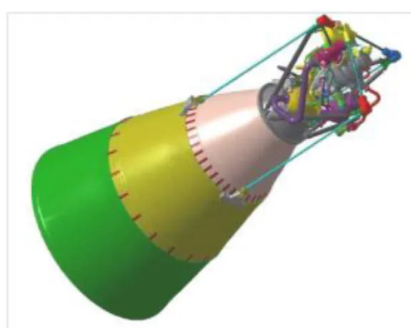
Figure 1: View of the Vinci expander-cycle engine with the nozzle extension deployed
[R6].
The liquid oxygen and hydrogen cryogenic engine is designed for multiple re-ignitions to increase the versatility of the A6 upper stage in delivering and positioning payloads in multiple high energy orbits. The re-start capability also allows a controlled de-orbiting or injection of the upper stage in graveyard orbit, hence contributing to the protection of the space environment from pollution and debris. An important contribution to the overall performance of the launcher is the engine chill-down. Prior to any Vinci starting sequence the propellant feeding lines, the turbo-pumps and their bearings must be properly preconditioned and cooled down. This process involves complex unsteady two-phase cryogenic flow due to the low boiling point of the propellants. The complexity of the problem results from the non-linear interaction of the fluid dynamics and heat transfer during phase-change. The initial phase of chill-down is dominated by the massive evaporation of the cryogens. As the system cools down, slugs of liquid entrained by the gas stream, flow through the system in a two-phase film boiling mode followed by the propagation of the liquid quenching front accompanied by nucleate boiling. As the system further cools down, the two-phase flow undergoes several flow regime transitions until it reaches a single-phase liquid flow. These phenomena are inherently unstable and can lead to extreme flow and pressure fluctuations. The flight hardware may also be subject to mechanical stresses due to thermal differential contraction.
Since the Vinci engine is designed to be reignited several times the chill-down phase has to be performed not only during the boost phase (EPC flight) of the lower stages but also during the upper stage coast phases. As a consequence of the significant difference in densities between the liquid and gas phases the reduced gravity condition strongly changes the flow patterns (with respect to the 1-g gravity level) and accordingly affects the momentum and energy equations. Boiling and two-phase flow behave differently when the gravity levels vary, leading to a significant reduction in heat exchange and therefore to a less efficient chill-down process with potentially higher consumption and longer cool down durations [R6]. A high efficiency of the chill-down process is therefore paramount and the cooling sequence must be optimized to achieve the minimum consumption of propellants within the established duration and temperature criteria whilst taking into account every extreme external boundary condition range value.
In order to address all these issues Snecma in partnership with CEA and Siemens developed the multi-physics code COMETE to meet the following goals:
Predict the flight performance of different chill-down methods and sequences in order to reduce the propellants consumption by numerical testing during the first boost and microgravity flight phases.
Predict the global behavior of the chill-down system, the duration to meet the temperature criteria of the turbo-pumps, with respect to the Net Positive Suction Pressure (NPSP) margins and the bearing temperature requirements. Perform structural analysis during the
thermal transient of the turbo-pumps assembly in order to identify thermal stress concentration areas.
Support the Vinci testing campaign activities.
Assess the risk of propellant solidification inside the chill-down purge lines and the margins with respect to the triple point pressure and temperature of the cryogens.
Predict the thrust generated by the vented cryogens.
The successful contribution of the multi-physics code COMETE to the Vinci engine Critical Design Review (CDR) regarding the chill-down performance simulations and feed valves opening sequences along with the study of degraded chill-down cases marked in 2014 the first milestone for the industrial application of the code [R11].
In order to further increase the capabilities of the code and to improve the simulation methodology and the flight prediction reliability an additional effort has been undertaken focusing on the specific problem of the chill-down under 0-g conditions [R7-R8]. In the past fundamental research activities have been carried out to study the heat transfer correlations and closure equations in microgravity to be later implemented in the numerical tool COMETE [R6]. Nevertheless the limited data available in terms of reproducibility (the duration experiments is relatively short due to technical constraints imposed by the 0-g experimental facilities [R8]), the range of control parameters and testing facility dependent phenomena due to simplified geometries and the specific designs constitutes a limitation to the validation of the numerical tools.
Specific testing activities aimed to verify independently firstly the chill-down model fitting procedure and secondly to compare and validate the performance of COMETE with respect to the flight telemetry data are being carried out in 2015. The Ariane 5 HM7B equipped ESC-A upper stage is used as a reference thanks to the availability of ground and flight data [R9]. In particular the simulation of microgravity chill-down sequences of specially instrumented Ariane 5 commercial flights will be performed. During such flights an additional chill-down sequence is performed on the HM7B/ESC-A upper-stage after the separation of the payload.
The article is structured as follows. After an introductory description of the multi-physics simulation tool COMETE and its components the standard conservative chill-down model fitting and flight simulation procedure is presented, detailing the steps starting from the
ground chill-down model up to the flight prediction simulation. The limits of the existing procedure are listed as well as the logic of the experimental numerical activities carried out to validate the global behavior of the code and the soundness of the fitting procedure by simulating the HM7B-equipped ESC-A upper stage.
3 NUMERICAL SIMULATION
TOOLS
3.1 Basis principles of COMETE
The coupling strategy of the COMETE software is based on the coupling of two independent softwares : the flow solver CATHARE developed by CEA and the conduction solver Samcef-Thermal developed by LMS-SAMTECH/Siemens (Liège, Belgium) controlled by a Master process called Supervisor. The Supervisor, also developed by LMS-SAMTECH/Siemens using the MPI message-passing library, allows data exchanges between the codes. The Supervisor sets the duration of the simulation, manages the initialization of the codes, launches the computation continuously adapting the frequency of data exchange and stops the simulation run when the final time is reached. In the following paragraphs the CATHARE code and Samcef-Thermal are briefly presented. For further information refer to the reference [R11].3.2 CATHARE
The CATHARE nuclear code, widely used for design and safety analyses in nuclear power plants, is used here to solve the complex hydrogen and oxygen two phase flows observed during the rocket engine chill-down. The CATHARE code is the outcome of more than 30 years of joint development effort by CEA, EDF (Electricité de France), AREVA-NP and IRSN (Radio-protection and Nuclear Safety Institute).
3.2.1 Main features
The development of the CATHARE code was initiated in 1979 [R12], as a joint effort of, at this time, CEA, EDF (the French utility), and FRAMATOME (the French vendor). The CATHARE code was originally devoted to best estimate calculations of thermal-hydraulic
transients, especially safety studies. At the end of the 1980s, CEA seized the opportunity to use CATHARE to perform studies for non-nuclear industrial applications such as cryogenic rocket engines.
In that context, there was a strong need to allow CATHARE to take into account not only water but also other fluids and to extend its capabilities to concepts other than light water reactors, including circuits with either single-phase gas or single-single-phase liquid flows, at both subcritical and supercritical pressures. It was decided to integrate the new capabilities as independent options in a unique standard version of the code, respecting the same stringent procedures for quality assurance, in order to benefit from a maximum reusability and to minimize development and maintenance costs. CATHARE has thus evolved in a reliable unique tool capable of studying a large number of concepts in the scope of a best-estimate code used for thermal-hydraulic nuclear safety analyses.
3.2.2 A single thermal-hydraulic
kernel
CATHARE has a flexible modular structure for the thermal-hydraulic modeling in applications ranging from simple experimental test facilities to large and complex installations. The main hydraulic components or elements are pipes (1-D), volumes (0-D), 3-D vessels and boundary conditions, connected to each other by junctions. Other sub-modules feature pumps and turbo-machines, control valves, T-junctions, sinks and sources, breaks and many other ones. All CATHARE modules are based on a six-equation two-fluid model (mass, energy and momentum equations for each phase), with additional optional equations for non-condensable gases and radio-chemical components. A specific treatment of the residual phases exists in order to manage their appearance and disappearance while minimizing convergence problems [R14] and with a quasi-perfect mass and energy conservation. The discretization of all terms of the equations is fully implicit in 1-D and 0-D modules and semi implicit in 3-D elements including inter-phase exchange, pressure and convection terms, and the resulting nonlinear equations are solved using an iterative Newton
solver. The code allows efficient use of several processors in parallel.
3.2.3 Common Quality Assurance
procedures
All applications of the CATHARE code follow the same full Quality Assurance procedures. The developing methodology of CATHARE includes non-regression tests for any new version or new release of updates. The non-regression tests, which are sampled from the assessment matrices, test all physical models, all modules and sub-modules and any type of transient. In addition, before each code new version delivery, portability tests ensure that the code predictions do not depend on the computer. The physical model developing methodology is based on:
Developments of models from separate effect tests or from literature, with possible adjustment of some coefficients.
Systematic assessment of the physical closure laws against a large matrix of Separate Effect Tests.
Extensive assessment on Integral Effect Tests in order to validate the general consistency of the set of physical closure laws.
As far as possible the same process is applied for the physical modeling for new applications. An extensive documentation is produced to describe the modules and sub-modules, to explain how to create an input deck and how to model the different reactor components. An important effort has been put on the User’s Guidelines document to specify the domain of application of the hydraulic and thermal components of the common kernel so that any user be aware of the conditions to be verified before using a common functionality. And, at last, there is a single team for maintenance and user support [R13].
3.2.4 A generic development
methodology
Although CATHARE is written using Fortran 77, its modular structure is quite close to the oriented object structure. The major interfaces involved in the data acquisition and in the writing of the calculation methods for the thermal-hydraulic elements are identified step by step: balance equations for mass, momentum and energy, equations of state and
closure relationships for the six-equation model, assembling of the jacobian matrix of the whole circuit and the associated linear algebra, user interface and coupling interface. In the framework of the code extension to other fluids and reactor concepts, the effort was then mainly put on listing out which methods and functionalities could be of common use for the various applications (i.e. to identify the thermal-hydraulic kernel) and which ones were specifically devoted to one particular application. The major differences between the applications lie firstly on the equations of state of the fluids, on the closure relationships for the interfacial and wall transfers and then on some components specific to their domain of application. Concerning the components, the functionalities (i.e. the associated equations and their closure relationships) are part of the thermal-hydraulic kernel, but the associated model data are not automatically available for all the other applications, or can be exclusively devoted to one application. When some thermal-hydraulic models are shared between different reactor concepts, they use common routines for the equations of state and for closure relationships. A good example is the thermodynamics of gas mixtures, for which an algorithm originally developed for the GFR application is now available for any other application.
3.2.5 Application of CATHARE to
rocket engine design
In the frame of COMETE development, an advanced thermal-hydraulic tool was needed for the numerical simulation of the behavior of the complex two-phase flows of the engine propellants (hydrogen and oxygen in subcritical and critical flows). Another requirement was to couple this thermal-hydraulic tool with other codes to calculate, among others, an accurate thermal behavior of the structures. The aim of the SNECMA/CEA joint project has been then to develop and to adapt CATHARE to fulfill the following requirements: simulate one-dimensional transient two-phase or single-phase flows for various fluids, perform several circuits containing control valves and pumps, developing interfaces for data exchange coupling and ensuring confidentiality of data.
The modular nature of CATHARE and the generic form of its equations has made it possible to plug physical and thermodynamic properties of cryogenic fluids (H2 and O2), in order to introduce CATHARE in the COMETE platform. The work, performed by CEA/DEN, consisted in the implantation of:
Cryogenic propellants thermodynamic tables
Physical and closure laws
Microgravity and heat transfer correlations
Coupling interfaces
We detail thereafter the new features that have been developed in the standard version of CATHARE for the needs of COMETE.
3.2.6 Specific and proprietary fluid
libraries
Physical properties and closure laws for hydrogen, covering a wide range of temperature and pressure for the hydrogen and the oxygen have been implemented in the V2.5_2 standard version. They are derived from the SIDONHY code [R15] [R16], which was previously developed by CEA, from 1990 to 2006, for rocket feed system analysis. At this time, they were experimentally validated on dedicated installations. They have been adapted to the numerical method of CATHARE.
In addition to those fluid properties libraries, the possibility to couple CATHARE with external thermodynamic libraries has also been developed.
3.2.7 Coupling
Interfaces allowing the use of the MPI library were developed to couple CATHARE to other codes. General developments have made CATHARE able to receive and treat any order coming from the Supervisor, such as:
“begin the calculation”, “exchange data”, “go forward”, “go backward”,
“modify the time step”, “end the calculation”.
Regarding the coupling with the thermal code SAMCEF-THERMAL it was decided that CATHARE would calculate the fluid variables and send them to the finite elements thermal
code, which would send back the wall temperatures. For this purpose, CATHARE defines fictitious walls that are only used to store numerical values, since CATHARE does not perform any thermal conduction calculation in this case. CATHARE has also to manage the correspondence between the meshing of its 1D fictitious walls and the THERMAL meshing.
3.2.8 Systematic tests policy
An important set of tests has been defined in order to permanently verify the ability of CATHARE when coupled with COMETE:
Grid tests (stand-alone), used to verify continuity and derivability of thermodynamic properties in every configuration.
Unit tests (stand-alone), used to verify different modules and basic configurations.
Global (industrial) tests (stand-alone and co-simulated), compared to VINCI experimental results.
These tests are performed every week and at every CATHARE release.
3.3 The SAMCEF-THERMAL code
SAMCEF-THERMAL is a 3D finite-elements thermal code, developed by LMS-SAMTECH/Siemens. Its software package includes linear and nonlinear, transient and steady state thermal analysis, with conduction, convection, radiations and potentially thermal ablation. Simple and complex thermal models can be created. Temperature distributions on the structure are computed, and can be used as loads for a further mechanical analysis. Snecma has developed a significant know-how on unsteady thermal modeling using the Samcef Thermal code in order to solve the thermal evolution of complex 3D parts of a rocket engine, such as the engine turbo-pumps and regenerative circuits of the combustion chamber.4 CHILL-DOWN MODEL
FITTING AND FLIGHT
SIMULATION PROCEDURE
4.1 Chill-down simulations logic
and methodology
The flight prediction simulation procedure applied to Vinci is based on the incremental update and fitting of the chill-down numerical COMETE models relying on the ground chill-down tests carried out during the development campaign to increase the representativeness of the chill-down model before its use to perform EPC 1st boost and coast phase flight chill-down predictions. This process is fully integrated with the Vinci engine development campaigns assuring the constant update of the engine definition (3D model). The following steps are carried out:
i. For each turbopump a COMETE chill-down model of the Vinci engine at the development test bench (DLR) is created.
ii. Simulations are carried out imposing the same thermodynamic initial conditions and boundary conditions as those experienced at the P4.1 test facility at DLR in Lampoldshausen. iii. Simulations results are compared with
the experimental measurements, focusing on the relationship between two phase flow regimes and heat transfer prediction, mass flow rates and flow repartition, turbopump cooling down rates, criteria reaching and localized pressure drops. The aim is to calibrate and validate the behavior of the ground thermal-hydraulic model against different chill-down sequences and boundary conditions settings. iv. The ground chill-down
thermal-hydraulic model is then adapted to fit the measured behavior.
v. The fitted ground model is transformed into a flight model by removing the P4.1 bench lines and adding the upper stage hydraulic lines. Two types of worst case scenario simulations are then executed:
a. A “temperature conservative” simulation,
b. A “consumption conservative” simulation.
The former simulation aims at verifying that the temperature criteria can be reached under the worst case scenario, i.e. with the maximum initial heating and flight hardware temperatures, the minimum hydrogen tank pressure and the shortest chill-down sequence whilst the latter simulation goal is to verify that the fuel consumption during chill-down stays within the limits set by the stage performance under the worst case scenario, i.e. with the minimum initial heating and temperatures, the maximum hydrogen tank pressure, and the longest chill-down sequence. Additional time-dependent boundary conditions are applied such as the inter-stage nitrogen venting, the external ambient pressure evolution and the launcher acceleration.
The tuning procedure introduces the assumption that the differences observed between the simulated ground chill-down phase and the P4.1 tests and the corrections introduced on the model are not only of the same order of magnitude but also that the same thermal-hydraulic phenomena as experienced during the EPC boost phase and the ballistic chill-down phases of the engine.
For example considering that the COMETE model is a 1D – 2D axial-symmetry model meaning that it cannot take into account tridimensional thermal gradients induced by non homogeneous boundary condition (i.e. uneven thermal load paths on the turbopump-engine assembly). The bias observed by comparing the ground chill-down experimental results against the simulation during the fitting procedure are still included in the flight model. The test bench measurement system is designed primarily for engine firing tests therefore it is not suited for low mass flow rates typical of a chill-down sequences. The mass flow rate flowing through the turbopump is therefore estimated as for the hydraulic pressure losses. With regards to the latter issue the fitting phase takes into account only the 1-g induced phenomena on the flow patterns (i.e. the gravity-induced stratification). The conservative approach maximizes the scattering of the boundary conditions which
can result on rather conservative chill-down durations and criteria reaching along with relatively high consumption rates.
4.2 Testing COMETE with the
Ariane 5/ESC-A flights
In order to improve the thermal-hydraulic code COMETE we designed a numerical testing campaign by setting the following goals:
i. To validate the global capability of the COMETE code to simulate the entire flight envelope of a propulsion system by investigating the thermal-hydraulic behavior of the turbopump predicted by the code during the first boost and the microgravity chill-down with respect to the statistics available on successful Ariane 5 flights
ii. To validate and assess independently the soundness of the conservative approach applied in the Vinci simulations with respect to the worst case scenario
Additional simulation objectives are also introduced to improve the use of the COMETE multi-physics simulation platform:
iii. To optimize the numerical model nodalization, assembly and thermal and hydraulic meshing procedure starting from the 3D CATIA model of the engine and the upper stage
iv. To test new modeling methodologies such as the extensive use of Samcef-Thermal shell-type elements to model the LOx and LH2 feed lines walls spanning from the tank outlets to the pump inlets.
The validation logic is based on a two-steps approach: (1) the simulation of existing flight hardware and commercial Ariane 5 missions and (2) the simulation of specific Ariane flights aimed to probe the physics and the technological challenges imposed by the microgravity environment on the propulsion system.
In the first step a numerical COMETE model of the HM7B engine and the ESC-A Ariane 5 upper stage is created and used to perform simulations of the upper stage ground chill-down to complete the thermal-hydraulic model fitting under measured control parameter
values reproducing the complete cold run of the ESC-A HM7B. Since this MR (Maquette de Remplissage) test article was designed to test the integration and the interaction between the engine and the upper stage cryogenic tanks, fluid lines and auxiliary systems simulating the entire spectrum of ground and flight sequences and conditions (except for the acceleration) that can occur during the lifecycle of the launcher, from the propellant loading to the emergency unloading, venting, pressurizing culminating with a static engine firing the number of temperature sensors and measurement telemetry channels are increased and exploitable.
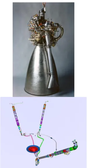
Figure 2: (Above) HM7B engine (Source: [R10]) and 3D model of the purge and feed
lines of the ESC-A upper stage modeled using COMETE (below).
The ground chill-down ESC-A MR simulations are carried out by imposing on the COMETE model the same boundary
conditions and initial conditions as measured on the fully instrumented HM7B engine and on the upper stage within the uncertainty range of the transducers. The boundary conditions consist of the propellant tank absolute pressures, propellant subcooling temperature, the ambient temperature surrounding the feed line and the HM7B engine.
This model will be used to perform the following calculations:
MR simulations for model tuning purposes
The worst case scenario EPC first boost chill-down flight simulations following the standard conservative approach using the old data input used during the upper stage development in the ‘80s
Execute a simulation of the instrumented flight with the averaged initial and boundary conditions of the complete set of Ariane 5/ ESC-A launches.
The comparison between the numerical predictions of the averaged flight along with the worst case scenario against the real Ariane 5/ECA flight data will provide valuable information on the soundness of the existing fitting procedure, the residual scattering of the data after the tuning phase and the improvement of the chill-down valve activation sequencing and margin reduction policy for the Vinci engine.
The second step consists in simulating a complete Ariane 5/ESC-A upper stage microgravity demonstration flight. This flight is characterized by a secondary chill-down sequence performed safely after the separation of the payload and before the neutralization sequence of the almost emptied ESC-A upper stage. Equipped with an increased in capabilities sensor and acquisition system this flight is designed to simulate the environment which will be encountered by the Vinci engine during its multiple re-ignition sequences with specific testing goals concerning also the upper stage spin-up, thermal management and propellant settling. The tuned COMETE model will be used to simulate the chill-down sequences for the oxygen and hydrogen circuits and in order to minimize the uncertainties regarding the engine boundary
conditions before the secondary chill-down, during the distancing phase, flight data will be recorded of the thermal status of the feed and purge lines thus allowing the update of the COMETE model initial conditions. This update will be useful to analyze the possible discrepancies between the simulated thermo-hydraulic global behavior of the propulsion system and the real one by highlighting hopefully the relative contribution of the microgravity environment with respect to other intrinsic model limitations.
This last step will be fundamental to understand and quantify the capabilities of the code to simulate such complex scenario to consolidate the flight prediction of the Vinci engine and to contribute substantially to the design and development phase of the Ariane 6 upper-stage with respect to the chill-down functional requirements and functions.
Figure 3: COMETE thermal map of the HM7B oxygen pump at the end of the chill-down sequence showing the propellant feed
lines modeled using the shell nodalization
4.2.1 The COMETE models
Two independent COMETE models are created for the oxygen and the hydrogen circuit respectively, since the thermal conductance across the geared HM7B engine turbopump unit is considered negligible with respect to the possibility of the mutual influence of two simultaneous chill-down sequences induced by the temperature difference of the propellants at boiling point. Each HM7B engine circuit consists of a 2D axisymmetric model of the pump impeller, and a 1D model of the chill-down and chamber fuel valves. The purge valve is also modeled and connected to the upper-stage purge lines. A new feature is the introduction of 3D feed and outlet (figure 3)
hydraulic lines modeled using Samcef-Thermal and the shell elements. This upgrade has been introduced to take into account the longitudinal thermal gradient established before the feed valve opening along the tube, the thermal conduction with the pump casing and also to better model the emplacement of the demonstration flight additional temperature sensors.
5 Preliminary results
In the following paragraphs we focused the attention on the preliminary results obtained by simulating the ground MR chill-down tests. The simulated ground chill-down sequence starts by opening the main fuel valve and the purge valve, allowing the complete cooling of the pump inlet and the evacuation of vapor pockets that may be trapped inside the secondary circuit. The instrumented HM7B engine allows a detailed analysis of its unsteady thermal behavior thanks to several thermocouples integrated inside the turbopumps. The transducers measuring the fluid temperature and the cooling down rate are compared with the numerical model results.
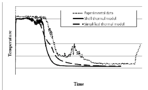
Figure 4 presents the temporal evolution of the pump inlet temperature obtained with the COMETE simulations and compared with the MR test reference, the experimental measurement. Two techniques, the CATHARE 1D simplified thermal model and the Samcef-Thermal shell nodalization have been tested to simulate the oxygen feed line are compared.
Figure 4: Temporal evolution of the oxygen pump inlet temperature evolution for different feed line modeling techniques compared to the MR ground chill-down
The slightly lower inlet temperature at the beginning of the chill-down seems to suggest the need to reduce the mass flow rate across the impeller or the increase of the heat flux within acceptable limit (as the end of the chill down seems to suggest). These adjustments are necessary to take into account the uneven thermal exchange coefficient and the localized pressure drops. The latter contribute significantly to the chill-down model fitting and results due to the difficulties in evaluating, to the limited experimental and analytical data available, the overlapping effect of the two-phase nature of the fluid and the tridimensional effects on the flow kinetic energy losses. The shell model anticipates the transition from the film boiling to the nucleate boiling regime if compared to the 1D simplified thermal model but the slower slope of the temperature evolution is in agreement within 10% with the MR test. The temperature increase observed during the MR test seems to be related to the cooling of a massive component leading to the reduction of the mass flow rate or the propagation of vapor pocket towards the tank.
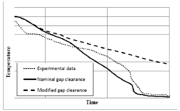
Figure 5: Temporal evolution of the oxygen pump bearing temperature evolution for different impeller gap clearances compared
to the MR ground chill-down data. Additional numerical tests have been performed to study the effect of the impeller clearance (figure 5) on the cooling dynamics of the pump impeller bearing. Satisfactory agreement between the COMETE model for the nominal design clearance tolerance and the experimental dataset is shown. While the measured slope of the temperature varies significantly with respect to the COMETE prediction the final transition to a fully liquid flow is achieved at the same instant attaining a steady state value within 10% of the measured value. This behavior suggests that the
modification imposed by the unavoidable tuning phase is not only correct but also that the COMETE code matches the underlying fluid-dynamic phenomena.
6 CONCLUSIONS AND
FURTHER DEVELOPMENTS
The state of the art multi-physics simulation software platform COMETE developed by Snecma in collaboration with the CEA and Siemens has been successfully used in 2014 to perform predictive studies of the Ariane 5 upper stage behavior during the chill-down phases and it is currently deployed to support the design and improvement phase of the Vinci rocket engine along with the test and qualification campaigns chill-down sequences trade-off [R11]. To meet the technical challenge CATHARE has been upgraded with hydrogen and oxygen thermodynamic tables and dedicated heat transfer closure equations exploiting existing and dedicated fundamental research activities carried out to study the heat transfer processes under various microgravity acceleration levels to meet the challenges of the 0-g ignition capability of the versatile Vinci engine.Nevertheless in a constant quest to the improvement of the capabilities of the COMETE platform a specific simulation campaign has been developed. This activity is based on an logic which links the Snecma experience in developing the HM7B engine with respect to the chill-down phase to the to the remarkable flight performance of the Ariane 5/ESC A HM7B-equipped upper stage, and looking forward to the future with the new scientific and technical challenges facing the development of the future Ariane 6/Vinci cryogenic upper-stage.. In order to seek for the improvement of the multi-physics platform performance and the validity of the modeling activities concerning especially the tuning and the flight prediction phases the extensive dataset of the MR ground chill-down tests of the ESC A is used as a reference. Preliminary results, obtained by simulating the MR chill-down sequences for the oxygen circuit show a satisfactory agreement between the experimental measurements and the simulations results in terms of chill-down
criteria reaching and overall thermal behavior of the HM7B pump.
The model will be used to predict the in-flight chill-down behavior of the ESC-A upper stage during the EPC boost phase, in order to explore the conservative approach used for the Vinci simulations by comparing the results with the conservative approach with the ultimate goal of optimizing the temperature and duration criteria. The process will be completed by the simulation of the ESC-A behavior under microgravity conditions taking advantage of the ESC-A 0-g demonstration flights. The final assessment of the code performance will allow not only the possibility to further improve COMETE but also the quality of the chill-down predictions in view to reduce the mass consumption on the overall performance of the propulsion system.
7 REFERENCES
[R1] “The Vinci upper stage engine : toward the demonstration of maturity”, P. Alliot et al., 64th International Astronautical Congress, 23-27 September 2013, China.
[R2] “Development of the A5ME Upper Stage”, A. Juhls et al., 49th AIAA/ASME/SAE/ASEE Joint Propulsion Conference and Exhibit, July 2013, California. [R3] “Progress of the Vinci engine system development”, P. Alliot et al., 46th AIAA/ASME/SAE/ASEE Joint Propulsion conference and Exhibit, July 2010, Tennessee. [R4] “Cold flow testing of revised engine chill-down methods for the Atlas Centaur”, J. Schuster et al., AIAA 96-3014, 1996.
[R5] “Progress of the Vinci engine system engineering”, P. Alliot et al., AIAA 2009-5038.
[R6] “Microgravity activities for the VINCI engine re-ignition capability”, A. Pacros, J. Follet and B. Veille, Proceeding of the microgravity Transport processes in fluid, Thermal Biological and Material science III, 2003, Davos, Switzerland.
[R7] “Overview of the development progress of the Ariane 5 Upper Stage VINCI engine”, P.
Alliot, et al., 53rd International Astronautical Congress, 2002 Texas.
[R8] “Microgravity two-phase flow and heat transfer” K. S. Gabriel, Springer 2007.
[R9] “From the qualification to 4th
year of exploitation: HM7B on ESC-A”, A. Lekeux, J. P. Pander et J. Mansouri, AIAA/ASME/SAE/ASEE Joint Propulsion Conference and Exhibit, 2009, Denver, AIAA 2009-5036
[R10] Safran corporate website, http://www.safran-group.com/.
[R11] “Evaluation of the Vinci rocket engine chill-down with COMETE, a new thermal-hydraulic software”. G.M. Moreau, P. Emonot, G. Dufraisse and D. Duri, Space Propulsion Conference 2014, Cologne, Germany
[R12] “CATHARE code development and assessment methodologies” J.C. Micaelli, F. Barré, D. Bestion,. ANS Winter Meeting, San Francisco, October 29-November 2, 1995. [R13] “CATHARE 2 V2.5_2 : a Single Version for Various Applications” G. Geffraye , O. Antoni, M. Farvacque, D. Kadri, G. Lavialle, B. Rameau, A. Ruby, NURETH-13, Kanazawa City, September 27-October 2, 2009.
[R14] “Methodology, status and plans for development and assessment of CATHARE code” D. Bestion, F. Barré, B. Faydide, Proc. of Int. Conf. OECD/CSNI, 5-8 November, 1996, Annapolis, USA.
[R15] “Two-phase flow modeling for rocket engine applications” J.C. Micaelli, B. Spindler, A. Memponteil, P. Danous, Hydrogen 92, June 22-25, 1992, Paris.
[R16] “Two phases thermalhydraulics for Ariane – an exemple of technological diffusion” J.C. Micaelli, B. Spindler, A. Memponteil, , Houille Blanche – Revue Internationale de l’eau volume 50, 1995.