HAL Id: hal-00299189
https://hal.archives-ouvertes.fr/hal-00299189
Submitted on 21 Apr 2005
HAL is a multi-disciplinary open access
archive for the deposit and dissemination of
sci-entific research documents, whether they are
pub-lished or not. The documents may come from
teaching and research institutions in France or
abroad, or from public or private research centers.
L’archive ouverte pluridisciplinaire HAL, est
destinée au dépôt et à la diffusion de documents
scientifiques de niveau recherche, publiés ou non,
émanant des établissements d’enseignement et de
recherche français ou étrangers, des laboratoires
publics ou privés.
Numerical analysis of deep-seated mass movements in
the Magura Nappe; Flysch Belt of the Western
Carpathians (Czech Republic)
I. Baron, F. Agliardi, C. Ambrosi, G. B. Crosta
To cite this version:
I. Baron, F. Agliardi, C. Ambrosi, G. B. Crosta. Numerical analysis of deep-seated mass movements
in the Magura Nappe; Flysch Belt of the Western Carpathians (Czech Republic). Natural Hazards
and Earth System Science, Copernicus Publications on behalf of the European Geosciences Union,
2005, 5 (3), pp.367-374. �hal-00299189�
Numerical analysis of deep-seated mass movements in the Magura
Nappe; Flysch Belt of the Western Carpathians (Czech Republic)
I. Baron1, 2, F. Agliardi3, C. Ambrosi3, and G. B. Crosta31Czech Geological Survey, branch Brno, Leitnerova 22, 658 69 Brno, Czech Republic
2Institute of Geological Sciences, Faculty of Science, Masaryk University, Kotlarska 2, 612 00 Brno, Czech Republic 3Dept. of Geological Sciences and Geotechnology, Faculty of Mathematical, Physical and Natural Sciences, Universit`a degli
Studi di Milano – Bicocca, Piazza della Scienza, 4, 20126 Milano, Italy
Received: 9 September 2004 – Revised: 16 March 2005 – Accepted: 5 April 2005 – Published: 21 April 2005 Part of Special Issue “Landslides and debris flows: analysis, monitoring, modeling and hazard”
Abstract. Deep-seated slope failures are common features
in the mountains of the Raca Unit, Magura Nappe of the Flysch Belt of Western Carpathians. Since they represent very complicated system, understanding of their evolution and triggers still remains unclear. We tried to provide a back-analysis of their development by using a finite differ-ence code (FDM) of continua (Flac 4.0). We confirmed that such large mass movements could be triggered by water sat-uration of the bedrock in the three particular geological and geomorphic settings. Such situation could have been caused by heavy rainfalls in humid phases of the Holocene or per-mafrost melting in Late Glacial. The effects of faulting, very deep weathering of the bedrock, low geotechnical parameters of smectite-rich material and the local slope geometry have also been accounted for in numerical models, as well as the other triggering factors of slope instability. FDM modelled shear zones are in agreement with observations.
1 Introduction
Deep-seated mass movements usually represent complex geomorphic processes, which are difficult to describe and model (Crosta and Zanchi, 2000). Understanding their struc-ture, origin and history requires a multidisciplinary and com-prehensive approach (Agliardi et al., 2001; Buccolini et al., 2002; Clerici et al., 2002). Beside classical methods of geomorphology, engineering geology and geophysics, other techniques have been successfully applied for their under-standing, e.g. dating techniques of quaternary geology, GIS, remote sensing or ground penetrating radar. Moreover, nu-merical modelling seems to be an essential part of such com-plex methods as a mathematical proof of field investigations
Correspondence to: I. Baron
(ivobaron@seznam.cz)
(Agliardi et al., 2001; Crescenti et al., 2002; Moser, 2003; Rainone and Sciara, 2003).
Deep-seated slope failures (DSSF) are pretty common fea-tures in the Flysch belt of the Western Carpathians. In this area, such phenomena have a strong influence on the land-scape morphology and land-use (Baron et al., 2004; Krejci et al., 2002). Nevertheless, the factors influencing DSSF development are only partially understood and difficult to analyse due to the very large-scale of the failure. In ad-dition to the specific geotechnical and tectonic features of the flysch bedrock, strong relief energy and high precipi-tations are expected to be main triggering factor of DSSF in the studied area. In fact, all the dated Carpathian deep-seated slope failures originated during “humid” phases of the Holocene and Late Glacial (Alexandrowicz and Alexandrow-icz, 1999; Kneblova-Vodickova, 1966; Margielewski, 2002). Also, only isolated re-activations of the DSSF after the 1997 rainfall event have been observed. During this event, up to 380 mm of precipitations occurred during four days (about four times higher values than the total average value for July), immediately followed by another high precipitations during the next weeks (Krejci et al., 2002).
In the present study we speculated, that extreme precipi-tations during the “humid” phases of the Holocene or melt-ing of permafrost durmelt-ing the late Galcial could lead to high ground water table level, much higher than in the present. Based on this idea, even there are missing the field data to confirm it well, we tried to demonstrate that such a high ground water table level could have been the trigger of such a large-scale failure in the three typical geological and geo-morphic settings in the Raca Unit of the Magura Nappe on territory of the Czech Republic. The study tries to confirm the results of previous study of Baron et al. (2004) by means of numerical modelling.
368 I. Baron et al.: Numerical analysis of deep-seated mass movements in the Magura Nappe
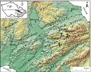
Fig. 1. Digital Elevation Model of the Flysch Belt of the
West-ern Carpathians in the Czech Republic. Studied slope failures: 1 = Kopce, 2 = Kobylska and 3 = Vaculov-Sedlo (after Baron et al., 2004).
2 Geological and geomorphic settings
2.1 Kopce case site
The first slope failure, the Kopce rockslide (Fig. 1), is sit-uated on the northern slope of Kopce Hill (699 m a.s.l.). This slide covers an area about 500 m long and 400 m wide (Fig. 2). The head of the failure is at an elevation of 675 m a.s.l, while the toe is located at about 500 m a.s.l. The slope failure has a volume of about 10 million m3of bedrock and colluvial deposits. The bedrock is composed of sandstone and conglomerate beds 15–20 m thick, alternated with se-quences of weaker claystone, shale, and thin-bedded sand-stone (total thickness: 10–15 m). These beds are related to an anticline of the Luhacovice Member, Zlin Formation (Fig. 2). The anticline strikes WSW-ENE and is disturbed by several transverse faults. One of these faults is expected to limit the rockslide from the W; the others probably in-fluenced the deep transverse cut of the Senice River. The anticline ridge is about 900 m wide at the foot of the east-ern slopes, while the ridge amplitude above the Senice River is about 260 m. The original surface sloped from 5◦to 25◦
in the rockslide area, and up to 40◦ on the eastern slopes.
The slide blocks are up to 150 m in size, about 20 m thick, and are limited by several meter-high steps on gravitational faults. The blocks are not back-rotated and their surfaces are regular, relatively flat, and covered with thin layers of de-bris. They slid onto the plastic and deformed “shale” layer below (Figs. 2B, 2C, and 3D). This shale contains swelling clay minerals, i.e. chlorite-smectite interstratified mineral as-semblages (Baron et al., 2004). The inner sandstone arc was displaced as well.
Fig. 2. Kopce slope failure: (A) Geomorphic map; Ground
Pen-etrating Radar (GPR) profiles Pf1 to Pf3 are performed. Legend of the failure observed at the ground surface: brown-block type one, yellow-plastic type one, red-pressure folds and ridges; (B) Cross section through the slope failure along Pf1; (C) Cross sec-tion through the slope failure along Pf2; (D) Cross-secsec-tion through the slope failure along Pf3 (after Baron et al., 2004).
2.2 Kobylska case site
The second studied slope failure is located at Kobylska (Fig. 1). The slope failure consists of a large slide about 800 m long and 500 m wide (Fig. 3), with 180 m of relief between head and toe and an estimated volume of about 16 million m3. This slope failure affected the bedrock in the upper part of the T-shaped Kobylska valley on the southern slopes of Lesti Hill (899.6 m a.s.l.). The slope inclination is 14.5◦in the upper part of the landslide area and up to 22◦in the lower part, sloping mainly concurrently (and partly oppo-site) to the bedding dip. Under a structural point of view, an anticline of the Zlin Formation trending E-W across the rock-slide area can be observed. Moreover, we have suggested the occurrence of a tectonic contact between the Beloveza and Zlin Formations within the slope failure. Unfortunately, there is no direct evidence of this contact at the surface; it is covered by colluvium. In this area, the bedrock consists of thin-bedded flysch with occasional 1–3 m thick layers of sandstone. Shales and colluvium of the Beloveza Forma-tion also include swelling clays (i.e. chlorit-smectite, vermi-culite). A near-scarp depression developed behind the main block at least 9080±9514C years BP dated by analysis of tree trunk in lower part of the sedimentary fill (Baron et al., 2004).
Fig. 3. Kobylska slope failure: (A) Geomorphic map, for legend
see the Fig. 2 caption; (B) Sketch of the slope failure structure, lon-gitudinal section: BF = Beloveza Formation., ZF = Zlin Formation (after Baron et al., 2004).
2.3 Vaculov-Sedlo case site
The Vaculov-Sedlo failure (Fig. 1) is situated on the south-ern and westsouth-ern slopes of Ptacnice Hill (830 m a.s.l.) and Prostredni Hill (743 m a.s.l.), at an elevation of 440 to 750 m a.s.l. In this area, the slope inclination ranges be-tween 10◦ and 15◦. The slide takes an area of at least of 2.5 km2(Fig. 4A) and is characterised by a volume up to 123 million m3. The slope failure developed in the flysch rock masses of the Beloveza and Solan Formations of the Raca Unit. In general, claystones and rocks of thin-bedded flysch sequences prevail. In the eastern part, these rocks are over-lain with 10–12 m thick sandstone and conglomerate, which have been sagged by gravity. The beds are gently folded and, in general, slightly dipping to the SE and NW. The weathered colluvium contains expanding clay mineral smectite and its interstratified assemblages with chlorite (Baron et al., 2004). Our study was focused on the easternmost part of the slide (Fig. 4B), where the bedding is sub-horizontal, and, which is strongly controlled by a 250 m wide NE-SW fault zone. The whole slide is characterised by a translational kinemat-ics, and is composed of back tilted rock blocks with an active shallow frontal landslide at their front. Although the entire easternmost part is a translational slope failure, the lower-most rotated blocks of the slide show specific dynamics and evolution. They seem to have been more intensely rotated,
Fig. 4. Sedlo: (A) Geomorphic sketch of the
Vaculov-Sedlo deep-seated slope failure; The investigated area is surrounded by a dashed line; (B) Detailed geomorphic map of the investigated area; Ground Penetrating Radar profiles Pf1 and Pf2 are shown, for legend see the Fig. 2 caption; (C) Cross-sectional interpretation of GPR record along Pf1; BF-Beloveza Formation, SF-Solan Forma-tion, 1 = uppermost block, 2 = tension zone at front of the rotated block, 3 = active shallow translational landslide and its older ac-cumulations, 4 = lower rotated block, 5 = unloading ruptures or new slip surfaces, 6 = deeply weathered bedrock along sub-vertical faults, 7 = accumulations of upper shallow landslides, 8 = expected buried pond sediments (after Baron et al., 2004).
possibly due to the presence of the erosional valley of the Bystricka River downslope. The blocks have been rotated up to 12◦and 27◦, respectively. The exact age of the displace-ments could not be ascertained, though it started certainly much earlier than 6100±250 14 C yr BP, when one of the upslope shallow landslide deposits filled the near-scarp de-pression (Baron, 2004).
3 Modelling approach
In order to achieve a better understanding of the factors con-trolling the evolution of the studied slope failures, back-analyses have been performed using the numerical code Flac 4.0, based on a finite difference approach (ITASCA, 2000). The code simulates the behaviour of continuum materials that may undergo plastic deformation and flow when their yield limits are reached. Materials are represented by two-dimensional finite difference grid of proper geometry. Each
370 I. Baron et al.: Numerical analysis of deep-seated mass movements in the Magura Nappe
Fig. 5. Structure of the Kopce model: 1, 3, 5, 7, 9, 11 = shale beds
and 2, 4, 6, 8, 10 = sandstone beds (for details see Table 1).
grid cell behaves according to a prescribed linear or non-linear stress/strain law in response to the applied forces or boundary conditions; the code also allows for the computa-tion of large strain (ITASCA, 2000). Thus, the code is able to account for large slope deformations and their evolution in 2D (Crescenti et al., 2002).
In our models, the original pre-slide slope geometry has been reconstructed by interpolating the neighbour slopes be-side the landslides. The constitutive model to be assigned to each slope forming material has been selected according to the geological features detected by fieldwork. The Flac 4.0 code provides several models, representing a specific type of constitutive behaviour associated with geologic materi-als (ITASCA, 2000). We adopted a Mohr-Coulomb plas-ticity model for the materials with negligible bedding (thick sandstone and shale beds etc.), while for the thinly bedded flysch bedrock we used the “ubiquitous-joint” constitutive model. The latter is more suitable for Mohr-Coulomb mate-rials, which exhibit a well-defined strength anisotropy due to embedded planes of weakness. The elastic (isotropic) model is valid for homogenous, isotropic continuous materials that exhibit linear stress-strain behaviour and it had been used for areas out of studied failures only.
A critical point of concern in the numerical modelling of large natural slopes is the relative lack of data related geotechnical properties of the slope materials, especially in the forested parts. The input data have been selected accord-ing to the results of laboratory geotechnical tests of bedrock and colluvium samples taken by boreholes from the Vaculov-Sedlo landslide site (Blaha et al., 2002; Sloboda et al., 1998) and from literature data. Some data were slightly adjusted according to specific considerations. For example, some co-hesion and friction angle values used in the models were slightly lower than those resulting from the geotechnical analyses on natural-moisture samples, because they are as-sumed to be weaker during swelling of the smectite-rich ma-terials (Ried-Soukup and Ulery, 2002).
Modelling has been performed by reached at first an ini-tial equilibrium state under gravitational loading and then performing alterations by including the actual geotechnical properties and introducing a water table near the surface. The water table level was expected very high (near the sur-face) as a result of extreme and long-lasting rainfalls or melt-ing of permafrost. Models have been run until slope failure, tracking the slope failure evolution during several modelling
Fig. 6. Structure of the Kobylska model: 1 = Beloveza Formation
and 2, 3, 4 = Zlin Formation with different bedding slope simulated by ubiquitous joints mode (for details see Table 2).
stages. The last stage represents rapid acceleration of the mo-tion and so development of a slide. Models have been cali-brated by comparing the computed displacements and defor-mations to the observed slope features, previously reported by Baron et al. (2004).
4 Numerical models
4.1 Kopce model
Modelling such a complicated geological setting such as arc structure is impossible without introducing any simplifica-tions. Thus, we modified the real bed thickness with respect to the grid geometry. The structure has been discretised into 11 regions, representing competent sandstone or weak shale beds (Fig. 5). The inner (stable) part of the anticline was uni-fied to simplify the computation of the model. Since there are no data on geotechnical parameters of the bedrock, we applied those ones from the Vaculov-Sedlo and slightly mod-ified them (Table 1). For example, the shales situated near the ground surface were assumed a bit weaker than those deeper ones. We adopted the Mohr-Coulomb model for the shales and the ubiquitous-joints model with vertical joint slope for tectonically jointed sandstones.
4.2 Kobylska model
Since in the Kobylska slope failure thin-bedded and folded flysch are the dominant rock types, we adopted the ubiqui-tous joint model and simplified the geometry of geological structures. The ubiquitous model allows only one joint set to be introduced for each region. Therefore we separated the model into 4 regions with different joint inclination (Fig. 6). The central anticline represented the regions 2 and 4. Since geotechnical data for this bedrock are missing, we adopted those from the Vaculov-Sedlo (Table 2).
5 mohr-coulomb upper shale 2100 5.00E+08 6.00E+08 1.00E+04 12 x x x x x
7 mohr-coulomb inner shale 2200 1.50E+09 8.00E+08 1.00E+04 15 x x x x x
region model type material ρ [kg.m-3] K [Pa] G [Pa] c
ef [Pa] φef [°] To [Pa] joint α [°] joint cef [Pa] joint φef [°] joint To[Pa]
1 ubiq. joints Beloveza Fm. 2500 2.00E+09 1.50E+09 2.00E+04 15 1.00E+04 45 0 15 0 2 ubiq. joints Zlin Fm. 2500 3.00E+09 1.50E+09 2.00E+04 20 1.00E+04 110 0 15 0 3 ubiq. joints Zlin Fm. 2500 3.00E+09 1.50E+09 2.00E+04 20 1.00E+04 60 0 15 0 4 ubiq. joints Zlin Fm. 2500 3.00E+09 1.50E+09 4.00E+04 25 1.00E+04 90 0 15 0
region model type material ρ [kg.m-3] K [Pa] G [Pa] c
ef [Pa] φef [°] To [Pa] joint α [°] joint cef [Pa] joint φef [°] joint To[Pa]
1 elastic Solan Fm. 2700 2.70E+10 7.00E+09 1.04E+07 39
2 ubiq. joints Beloveza Fm. 2600 1.00E+09 1.50E+09 2.00E+04 22 1.00E+04 170 8.00E+03 20 3.00E+03 3 ubiq. joints weathered B.Fm. 2300 5.00E+08 8.00E+08 5.00E+03 11 3.00E+03 170 6.00E+03 20 3.00E+03
Table 2. Review of input data for the Kobylska model. Legend: ρ – density, K – bulk modulus, G – shear modulus, φef – friction angle,
cef – cohesion, T0– tensile strength, joint α – ubiquitous joint angle.
region model type material ρ [kg.m-3] K [Pa] G [Pa] c
ef [Pa] φef [°] To [Pa] joint α [°] joint cef [Pa] joint φef [°] joint To[Pa]
1, 3, 9, 11 mohr-coulomb side shale 2400 6.60E+09 2.20E+09 1.00E+04 15 x x x x x 2, 4, 6, 8 ubiq. joints sandstones 2600 2.60E+10 7.00E+09 1.04E+07 39 x 90 1.00E+04 15 x
5 mohr-coulomb upper shale 2100 5.00E+08 6.00E+08 1.00E+04 12 x x x x x
7 mohr-coulomb inner shale 2200 1.50E+09 8.00E+08 1.00E+04 15 x x x x x
region model type material ρ [kg.m-3] K [Pa] G [Pa] c
ef [Pa] φef [°] To [Pa] joint α [°] joint cef [Pa] joint φef [°] joint To[Pa]
1 ubiq. joints Beloveza Fm. 2500 2.00E+09 1.50E+09 2.00E+04 15 1.00E+04 45 0 15 0 2 ubiq. joints Zlin Fm. 2500 3.00E+09 1.50E+09 2.00E+04 20 1.00E+04 110 0 15 0 3 ubiq. joints Zlin Fm. 2500 3.00E+09 1.50E+09 2.00E+04 20 1.00E+04 60 0 15 0 4 ubiq. joints Zlin Fm. 2500 3.00E+09 1.50E+09 4.00E+04 25 1.00E+04 90 0 15 0
region model type material ρ [kg.m-3] K [Pa] G [Pa] cef [Pa] φef [°] T
o [Pa] joint α [°] joint cef [Pa] joint φef [°] joint To[Pa]
1 elastic Solan Fm. 2700 2.70E+10 7.00E+09 1.04E+07 39
2 ubiq. joints Beloveza Fm. 2600 1.00E+09 1.50E+09 2.00E+04 22 1.00E+04 170 8.00E+03 20 3.00E+03 3 ubiq. joints weathered B.Fm. 2300 5.00E+08 8.00E+08 5.00E+03 11 3.00E+03 170 6.00E+03 20 3.00E+03
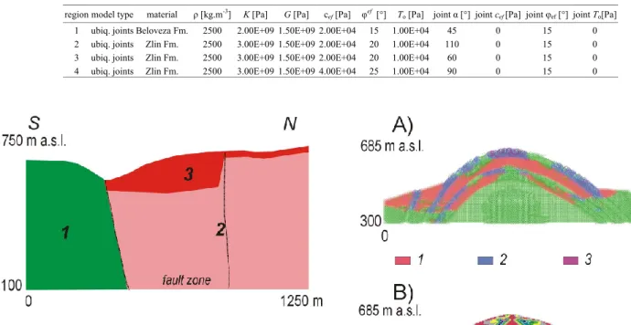
Fig. 7. Structure of the Vaculov-Sedlo model: 1 = Solan
Forma-tion, 2 = Beloveza FormaForma-tion, 3 = intensively weathered Beloveza Formation (for details see Table 2).
4.3 Vaculov-Sedlo model
In the studied section of the Vaculov-Sedlo slope failure, two main lithological units occur, i.e. the stable sandstones of the Solan Formation and the Beloveza Formation, disturbed by the fault zone (diagonally to the model section). This geo-logical structure of the bedrock was generalised for the mod-elling (Fig. 7). We separated it into 3 regions. The Beloveza Formation is represented by two of them, i.e. the unweath-ered and weathunweath-ered ones. A review of geo-technical param-eters is presented in Table 3. The role of the fault zone was thought to draw down relatively deep weathering of bedrock. Therefore we applied weaker material properties into the depth of at about 100 m in the model along the fault zone. Sub-horizontal bedding of thin-bedded flysch sloping against the slope was imitated by using ubiquitous-joints model.
Fig. 8. Results of FDM modelling of the Kopce slope failure at final
stage of computation: (A) plasticity indicators: 1 = at yield in shear or volume, 2 = slips along ubiquitous joints, 3 = at yield in tension, 4 = elastic, at yield in past, (B) location of shear strain.
5 Numerical modelling results
5.1 Kopce model
In the model, both sides of the anticlinal ridge appeared to have deformed (Fig. 8A) after introducing the water table. The maximum shear strain was concentrated at the base of the upper shale layer in the lower part of the ridge; a minor one occurred also at the base of the inner shale on the left-hand side of the model section (Fig. 8B). The shear band ge-ometry appears to be strongly controlled by the dip of the un-derlying sandstone bed. Another minor shear band has been
372 I. Baron et al.: Numerical analysis of deep-seated mass movements in the Magura Nappe
Table 3. Review of input data for the Vaculov-Sedlo model. Legend: ρ – density, K – bulk modulus, G – shear modulus, φef – friction
angle, cef – cohesion, T0– tensile strength, joint α – ubiquitous joint angle.
region model type material ρ [kg.m-3] K [Pa] G [Pa] c
ef [Pa] φef [°] To [Pa] joint α [°] joint cef [Pa] joint φef [°] joint To[Pa]
1, 3, 9, 11 mohr-coulomb side shale 2400 6.60E+09 2.20E+09 1.00E+04 15 x x x x x 2, 4, 6, 8 ubiq. joints sandstones 2600 2.60E+10 7.00E+09 1.04E+07 39 x 90 1.00E+04 15 x
5 mohr-coulomb upper shale 2100 5.00E+08 6.00E+08 1.00E+04 12 x x x x x
7 mohr-coulomb inner shale 2200 1.50E+09 8.00E+08 1.00E+04 15 x x x x x
region model type material ρ [kg.m-3] K [Pa] G [Pa] c
ef [Pa] φef [°] To [Pa] joint α [°] joint cef [Pa] joint φef [°] joint To[Pa]
1 ubiq. joints Beloveza Fm. 2500 2.00E+09 1.50E+09 2.00E+04 15 1.00E+04 45 0 15 0 2 ubiq. joints Zlin Fm. 2500 3.00E+09 1.50E+09 2.00E+04 20 1.00E+04 110 0 15 0 3 ubiq. joints Zlin Fm. 2500 3.00E+09 1.50E+09 2.00E+04 20 1.00E+04 60 0 15 0 4 ubiq. joints Zlin Fm. 2500 3.00E+09 1.50E+09 4.00E+04 25 1.00E+04 90 0 15 0
region model type material ρ [kg.m-3] K [Pa] G [Pa] c
ef [Pa] φef [°] To [Pa] joint α [°] joint cef [Pa] joint φef [°] joint To[Pa]
1 elastic Solan Fm. 2700 2.70E+10 7.00E+09 1.04E+07 39
2 ubiq. joints Beloveza Fm. 2600 1.00E+09 1.50E+09 2.00E+04 22 1.00E+04 170 8.00E+03 20 3.00E+03 3 ubiq. joints weathered B.Fm. 2300 5.00E+08 8.00E+08 5.00E+03 11 3.00E+03 170 6.00E+03 20 3.00E+03
Fig. 9. Results of FDM modelling of the Kobylska slope failure at
final stage of computation: (A) plasticity indicators: 1 = at yield in shear or volume, 2 = slips along ubiquitous joints, 3 = at yield in tension, 4 = elastic, at yield in past, (B) location of shear strain.
observed in the model in the upper part of the slope near the top. It was oriented horizontally across the sandstone layer. In general, the lower part of the upper sandstone was deformed along ubiquitous joints and the upper part was de-formed both in tension and along ubiquitous joints (Fig. 8A). Sandstone in the middle part of the slope followed an elas-tic behaviour, whilst most of the shale deformed by shear or volume. The model failed later than the other models (time step 45 500), when the landslide occurred.
5.2 Kobylska model
During the development of the model, a narrow circular slip zone developed (Fig. 9). The shear band crossed the bedding in all of the regions except the first one, where the bedding direction appeared to control the development of shear strain (compare Figs. 6 and 9B). Above the slip zone, where the material failed in shear or volume, relatively intact block de-veloped. The block underwent elastic deformation or local internal deformation along ubiquitous joints (Fig. 9A). Slips along ubiquitous joints also developed near the top of the an-ticline and in the upper part of the shear zone. The slide fully developed during the time step 13 000, when the grid reached a bad geometry due to excessive strain following failure. 5.3 Vaculov-Sedlo model
Also in the Vaculov-Sedlo model, high ground-water table triggered the bedrock failure. Here the failure was located within the weathered zone of the Beloveza Formation, devel-oped along the fault zone (Fig. 10A). Two superimposed and quite sharp rotational shear zones separating two relatively intact blocks developed in the model (Fig. 10B), following the real situation observed by the field investigations. The material was deformed by shear or volume mostly, except rare tension by unloading close to the head area (Fig. 10A). The model failed during the time step 9060, when the slide occurred.
6 Discussion
We tried to proof by means of numerical modelling, that very extreme climatic conditions, which uplift the ground water table up to near the ground surface, could have triggered deep-seated rockslides in the flysch belt of Western Carpathi-ans. We have chosen three particular deep-seated slope fail-ures, all situated in the Raca Unit of the Magura nappes. The three slope failures have already been a subject of the com-plex interdisciplinary study by the first author (Baron, 2004; Baron et al., 2004).
Despite numerical modelling always requires a simplifica-tion, we tried to introduce as many as possible particular ge-ological, structural and geomorphic features, as detected at each studied site by detailed fieldwork (Baron, 2004; Baron et al., 2004). Particular attention has been paid when mod-elling lithological and tectonic factors (e.g. local faulting, folding, bedding, original surface slope etc.).
of the ridge. Also in the case of the Kobylska slope failure, where quite a simple rotational shear zone is expected at the depth of about 110 m, results of field surveys coincide with the model results at the same depth. Finally, in the eastern part of the Vaculov-Sedlo slope failure we expect two su-perimposed slope-failure blocks. Their rotational slip zones developed within the fault zone at maximal depths of 40 and 70 m. Model results show very similar structures: two main and superimposed shear zones at the base of two relatively intact blocks. The lowermost shear zone had developed at base of intensively weathered bedrock in the model and it was the older one.
The studied deep-seated slope failures could be trig-gered in the periods of extraordinary rainfalls during phases of the Holocene, which are believed to be the humid ones, and during periods of permafrost melting in Late Glacial, as suggested by Alexandrowicz and Alexandrowicz (1999), Kneblova-Vodickova (1966), Margielewski (2002), Hradecky and Panek (2003). This fact is partly supported by 14C dating of the studied slope-failure-related deposits (Baron, 2004). The cold and relatively dry periods of the ice ages (full glacials) could be speculated as a time when deep-seated mass movements were halted in the area (Baron, 2004).
We observed only isolated re-activation of the DSSF after the 1997 rainfall event (Baron et al., 2004). In contrast to the 1997 event, the bedrock saturation during the studied slope-failures origination should be much higher.
7 Conclusions
Finite difference numerical modelling supported the hypote-sis that large mass movements could have been triggered by water saturation of the bedrock and high water table (close to the ground surface) in the three particular geological and geomorphic settings in the Flysch Belt of the Western Carpathians. Such conditions could have occurred as a result of heavy rainfalls in humid phases of the Holocene or result of permafrost melting in Late Glacial (Margielewski, 2002). In those periods, rainfalls should have been more intense and long-lasting ones than those that occurred in 1997, which only led to minor reactivation of the studied failures. The intensive faulting, very deep weathering of the bedrock, low geotechnical parameters of smectite-rich material and the local topography were simulated as the other factors of the deep-seated mass movement triggering. The FDM modelled shear zones are similar to those ones, developed in natural conditions in the three case sites.
Fig. 10. Results of FDM modelling of the Vaculov-Sedlo landslide
at final stage of computation: (A) plasticity indicators: 1 = at yield in shear or volume, 2 = slips along ubiquitous joints, 3 = at yield in tension, 4 = elastic, at yield in past, (B) location of shear strain.
Edited by: M. Arattano
Reviewed by: M. Jaboyedoff and another referee
References
Agliardi, F., Crosta, G., and Zanchi, A.: Structural constraints on Deep Seated Slope Deformations Kinematics, Engineering Ge-ology 59, 1–2, 83–102, 2001.
Alexandrowicz, S. W. and Alexandrowicz, Z.: Recurrent Holocene Landslides: a Case Study of the Krynica Landslide in the Polish Carpathians, The Holocene 9, 1, 91–99, 1999.
Baron, I.: Structure, Dynamics and History of Deep-seated Slope Failures in the Raca Unit, Flysch Belt of Outer Western Carpathi-ans (Czech Republic), MS, Ph.D. thesis, Masaryk University, Brno, 98 pp., 2004.
Baron, I., Cilek, V., Krejci, O., Melichar, R., and Hubatka, F.: Structure and Dynamics of Deep-Seated Slope Failures in the Magura Flysch Nappe, Outer Western Carpathians (Czech Re-public), Nat. Haz. Earth Sys. Sci., 4, 549–562, 2004,
SRef-ID: 1684-9981/nhess/2004-4-549.
Blaha, P., Duras, R., and Skopal, R.: Vaculov – geofyzika, MS., Investigation Report, Geotest Brno, branch Ostrava, Ostrava, 15 pp., 2002.
374 I. Baron et al.: Numerical analysis of deep-seated mass movements in the Magura Nappe
Buccolini, M., Sciara, N., and Mataloni, G.: An Integrated method-ology for the study of a complex landslide: the case of Pescosan-sonesco (central Italy), in: Landslides – Proceedings of the 1st European Conference on Landslides, Prague, Czech Republic, 24–26 June 2002, edited by: Rybar, J., Stemberk, J., and Wag-ner, P., Swets & Zeitlinger, Lisse, 117–122, 2002.
Clerici, A., Mandrone, G., Tellini, C., and Vescovi, P.: The Geo-morphological and kinematic evolution of the Anzola Landslide, in: Landslides – Proceedings of the 1st European Conference on Landslides, Prague, Czech Republic, 24–26 June 2002, edited by: Rybar, J., Stemberk, J., and Wagner, P., Swets & Zeitlinger, Lisse, 143–148, 2002.
Crescenti, U., Sciarra, N., Gentili, B., and Pambianchi, G.: Mod-elling of complex deep-seated mass movements in the central-southern Marches (Central Italy), in: Landslides – Proceedings of the 1st European Conference on Landslides, Prague, Czech Republic, 24–26 June 2002, edited by: Rybar, J., Stemberk, J., and Wagner, P., Swets & Zeitlinger, Lisse, 149–155, 2002. Crosta, G. and Zanchi, A.: Deep seated slope deformations: huge,
extraordinary, enigmatic phenomena, in: Acta of the VIII Inter-national Symposium on Landslides, Cardiff, Great Britain, edited by: Bromhead, E., 1, 351–358, 2000.
Hradecky J. and Panek T.: Slope processes of the Czech part of the Silesian Beskydy Mts. Occurence, Preconditions and Dating, in: Geomorphologia Slovaca, edited by: Lacika, J., Abstracts, CBCG, 3, 1, 35, 2003.
ITASCA: FLAC (Fast Lagrangian Analysis of Continua) user’s manual, ITASCA Consulting Group, Minneapolis, MN, 2000.
Kneblova-Vodickova, V.: Paleobotanicky vyzkum raseliniste v
Beskydech (Paleobotanical Survey of a peat-bog in Beskydy Mts.), Vestnik UUG, 41, 271–278, 1966.
Krejci, O., Baron, I., Bil, M., Jurova, Z., Hubatka, F., and Kirchner, K.: Slope movements in the Flysch Carpathians of Eastern Czech Republic triggered by extreme rainfalls in 1997: a case study, Phys. Chem. Earth, 27, 2002, 1567–1576, 2002.
Margielewski, W.: Late Glacial and Holocene Climatic Changes Registered in Landslide Forms and their Deposits in the Polish Carpathians, in: Landslides – Proceedings of the 1st European Conference on Landslides, Prague, Czech Republic, 24–26 June 2002, edited by: Rybar, J., Stemberk, J., and Wagner, P., Swets & Zeitlinger, Lisse, 399–404, 2002.
Moser, M.: Geotechnical measurements for assessment of the kine-matic and long-term behaviour of unstable mountainsides, in.: Geotechnical Measurements and Modelling. – Proceedings of the International Symposium on Geotechnical Measurements and Modelling, 23–25 September 2003, Karlsruhe, Germany, edited by: Natau, O., Fecker, E., Pimentel, E., A. A. Balkema, 217–223, 2003.
Rainone, M. L. and Sciara, N.: A multidisciplinary integrated ap-proach to geological and numerical modelling of the Lodrone landslide (Oriental Alps, Trentino Region, Italy), in.: Geotech-nical Measurements and Modelling – Proceedings of the Inter-national Symposium on Geotechnical Measurements and Mod-elling, 23–25 September 2003, Karlsruhe, Germany, edited by: Natau, O., Fecker, E., Pimentel, E., A. A. Balkema, 225–230, 2003.
Reid-Soukup, D. A., Ulery, A. L.: Smectites, in: Soil Mineralogy with Environmental Applications, edited by: Dixon, J. B. and Schulze, D. G., Soil Science Society of America, Inc. Madison, USA, 467–499, 2002.
Sloboda, J., Sekyra, Z., Kujal, R., and Travnickova, E.: Mala Bystrice – tabor Tatry, Geotechnicky pruzkum sesuvu, MS., S.G.-Geotechnika, Ostrava, 35 pp., 1998.