Development of a Morphing Helicopter Blade with
Electrochemical Actuators
by
Fernando Tubilla Kuri
B.S., Mechanical Engineering (2003)Universidad Iberoamericana, Mexico City
Submitted to the Department of Mechanical Engineering
in partial fulfillment of the requirements for the degree of
Master of Science in Mechanical Engineering
at the
MASSACHUSETTS INSTITUTE OF TECHNOLOGY
February 2007
@
Massachusetts Institute of Technology 2007. All rights reserved.
A uthor ...
...
Department of Mechanical Engineering
January 17, 2007
Certified by...
.. ...
.,...Steven Ray Hall, ScD
Professor o, Aeronautics and Astronautics
Thesis Supervisor
Certified by,....
. . . .. . . . .
Martin Culpepper, PhD
Rockwell International.Aociate Professor Of Mechanical Engineering
Thesis Reader
A ccepted by ...
...
MASSACHUSETTS INSnTIE OF TECHNOLOGYAPR
i
9
2007
LIBRARIES
ARCWIVEs
Development of a Morphing Helicopter
Blade with Electrochemical Actuators
by
Fernando Tubilla Kuri
Submitted to the Department of Mechanical Engineering on January 17, 2007 in Partial Fulfillment of the Requirements for the Degree of Master of Science in
Mechanical Engineering
Abstract
The use of the expansion of electrochemical cells, upon ion intercalation, for the de-velopment of a morphing helicopter blade is explored. Using commercially available lithium-ion batteries as demostrators of the technology, two actuator prototypes suit-able for the application are developed. The first prototype consists of a weave of fibers enclosing an array of cells in such a way that the thru-thickness expansion of the cells is transformed into an in-plane contraction. A mathematical model of the actuator is developed and used for the prototype design, which is then implemented using three cells and steel wires. Tests performed on the prototype show that, after accounting for viscoelastic phenomena, the prototype free strain agrees well with the model predictions.
A Blade Element Momentum Theory model of the helicopter rotor, used for the design of the second actuator prototype, is described. The model is used for evaluating a morphing scheme in which the blade deforms its trailing edge by different amounts along the span. Under this scheme, a suitable blade twist in terms of forward flight performance can be selected, and the trailing edge deflection is then used to improve the performance in hover. Applying the model to a Bell 427 helicopter, it is found that, starting with a blade with 40 less twist than the baseline blade and an expanding cell with an energy per mass of 78 J/kg, it is possible to generate enough flap deflection to improve hovering performance by about 1%, with an actuator that increases the blade mass by less than 10%.
The design of a blade actuator based on this trailing edge deflection scheme is then described. It consists of a pair of stacks enclosed inside the blade spar, transfering their motion to the flap via two pushrods and a set of steel flexures. A lumped-parameter model is used for the design and optimization of the actuator, and it is
later validated using a finite element software package. Results from the tests on
a short scaled section of the morphing blade are presented and compared with the theoretical model.
Acknowledgements
The present thesis has been the product of two years of work, in which a great deal of people contributed to my learning and enjoyment of this experience.
In a professional level, I am deeply thankful to my advisor, Professor Steve Hall, for his guidance and for constantly pushing me to become a better engineer. Kungyeol Song played an important role during the first year of the project, and I thank him for his continuous support and encouragement. The project was greatly enriched
by our interaction with Professor Yet-Ming Chiang and his research group. I thank
Professor Chiang for his support and enthusiasm throughout the project. Tim, Georg, Dimitrios, and Urs were great company and made the work much more fun. Professor Culppeper kindly helped reading my thesis, and I thank him for taking time from his busy schedule to do so. I would also like to thank all the people that helped with the construction and testing of the actuator prototypes, including John Kane, Donald Galler, Mark Belanger, and Todd Billings.
Looking back at the past two years, I am amazed of how much I have grown not only on a professional level but also -and especially- on a personal level. The friendships I have made along the way are invaluable. I thank Federico, Chris, Selim,
Jesus, Gerardo, Daniela, and all the rest for the great times we had, and for those to come. I am also deeply thankful to Tim and Joe, for making me a far better musician than I would have ever thought capable of becoming.
Finally, this whole experience would have not been possible without the continuous support from my family and friends in Mexico. I thank mama, for not having missed even a single day thinking (and worrying) about me. Papa, for his always thoughtful advice. Alby, for his friendship, and Mon, for always setting an example on how to
live this life. I also thank my numerous friends in Mexico... their 4:00 am phone calls from Baby'O were always welcomed!
This work was supported by DARPA (contract No. W911W6-05-C-0013), with Dr. John Main and Dr. Louis Centolanza serving as project managers.
Contents
1 Introduction 17
1.1 The Promises and Challenges of
Electrochemical Actuators . . . . 18
1.1.1 Linear Active Materials Modeling . . . . 19
1.1.2 Theoretical Considerations of Electrochemical Actuators . . . 21
1.1.3 First-generation Electrochemical Actuators . . . . 22
1.2 Motivation for an Electrochemical Smart Blade . . . . 24
1.3 Thesis Scope and Organization . . . . 29
2 Design of a Woven Actuator Concept using Lithium-Ion Cells 33 2.1 Mechanical Actuation Properties of Lithium-Ion Cells . . . . 34
2.2 Electrochemical Woven Actuator Design . . . . 36
2.2.1 Actuator Design . . . . 38
2.2.2 Construction . . . . 44
2.2.3 Testing . . . . 49
2.2.4 Results and Analysis . . . . 51
2.2.5 Conclusions . . . . 56
3 Morphing Blade Modeling 59 3.1 Hover Flight M odel . . . . 59
3.2 Model Implementation . . . . 66
3.2.1 Modeling of a Blade with a Trailing Edge Flap . . . . 69
3.3 Morphing Scheme Design and Requirements . . . . 72
4 Prototype Design and Testing 81 4.1 Actuator Concept . . . . 81
4.2 Actuator Modeling . . . . 87
4.3 Prototype Design . . . ... 93
4.3.1 Design with Projected First-Generation Electrochemical Actu-ators . . . . 95
4.3.2 Design with Commercial Li-Ion Batteries . . . . 96
4.4 Model Validation using FEA . . . . 98
4.5 Prototype Testing . . . . 100
4.5.1 Data Analysis . . . . 107
5 Conclusion 111 5.1 Summary of Results . . . . 111
5.2 Suggestions for Further Research . . . . 114
A Aerodynamic-Model MATLAB Code 119 B Blade Prototype Construction 149 B.1 M ethod . . . . 149
B.2 Engineering Drawings . . . . 160
List of Figures
1-1 Illustrative example of an active material under different boundary
conditions . . . . 20
1-2 Characteristic curves of a general active element (or actuator) for dif-ferent activation states and loads. . . . . 21
1-3 Schematic of micromachined cell with highly oriented pyrolitic graphite (HOPG) and picture of load-bearing posts (reproduced from [7]) . . . 23
1-4 Laminated actuators made of LiCoO2 and graphite electrodes, in a design similar to current commercial batteries (from [7]). . . . . 24
1-5 Comparison of first-generation electrochemical actuators with other active material technologies (based on [11]). . . . . 25
1-6 Performance Comparison for two blades with different amount of twist 26 1-7 Vibration loads comparison for two blades with different amount of twist 27 1-8 Typical design space for blade built-in twist (based on [14]). . . . . . 28
1-9 Electrochemical morphing-blade concept description. . . . . 28
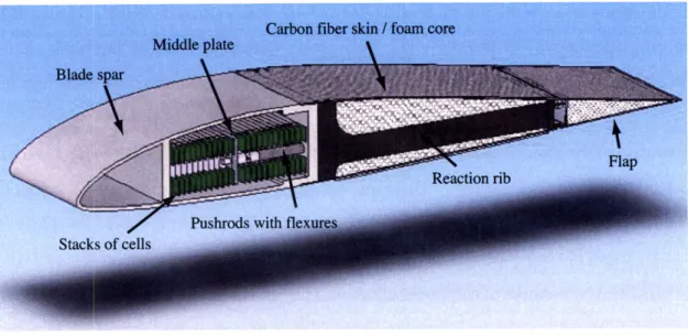
1-10 Section of the morphing blade actuator proposed in this thesis. . .... 30
2-1 Lithium-ion cell strain measurements under 5 MPa. . . . . 34
2-2 Lithium-ion cell strain measurements under 15 MPa. . . . . 35
2-3 Woven Actuator Concept. . . . . 37
2-4 Actuator unit with design variables defined. . . . . 38
2-5 Actuating Unit before activation and after activation, under an exter-nal load. Note that the caps are not shown for clarity. . . . . 39
2-7 Load-displacement characteristic curve for a single unit of the Woven
Actuator model. . . . . 41
2-8 Battery strain versus actuator output strain from the free strain con-dition to the blocked concon-dition. . . . . 43
2-9 Actuator stiffness and free strain as a function of L/w (one unit) . . . 43
2-10 Total actuator thickness as a function of L/w . . . . 44
2-11 Mechanical Efficiency of the Woven Actuator as function of L/w. . . 45
2-12 Lithium-ion battery with aluminum caps ready to be bonded . . . . . 45
2-13 Close-up of battery unit with improper cap bonding. Notice the sliding of the caps. . . . . 46
2-14 Batteries with caps ready for weaving. . . . . 47
2-15 Comparison of 2 possible weaving methods: single-wire weave (left) and double-wire with twist weave (right). . . . . 47
2-16 Woven Actuator Sample close-up, ready for testing. . . . . 48
2-17 Woven Actuator test setup . . . . 50
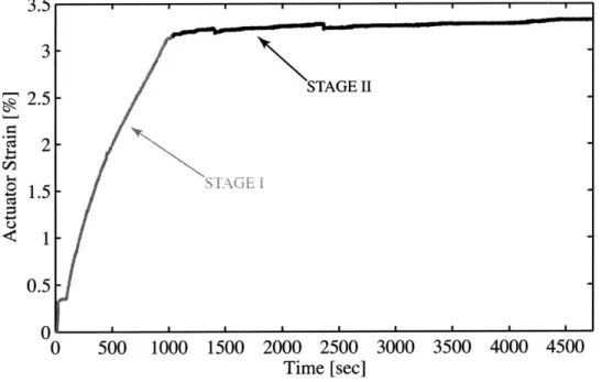
2-18 Actuator output strain during the constant-rate loading at 120 N/min and constant-load at 1800 N stages of the test. . . . . 52
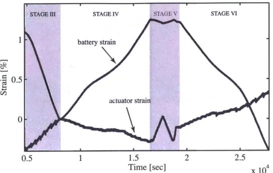
2-19 Actuator and battery strains during Stages III - VI of the test. ... 53
2-20 Strains with Stage V removed and extrapolated creep curves superim-posed. ... ... 54
2-21 Actuator and battery strains with creep behavior removed. . . . . 54
2-22 Actuator measured strain and battery strain amplified using the theo-retical value of 0.226. . . . . 55
2-23 Actuator force output during stiffness test (Stage V). . . . . 56
2-24 Comparison of actuator and battery strains during the stiffness test. . 57 3-1 Momentum Theory analysis of the helicopter in hover. . . . . 60
3-2 Blade Element analysis during hover. . . . . 62
3-3 Control Volume used for BEMT analysis of rotor in hover. . . . . 65
3-5 Block Diagram of the hover model implementation. . . . . 68 3-6 VR7 airfoil with a flap located at Xh and having a deflection 6. ... 70
3-7 Linearized Hinge Coefficients CH, (left) and CH, (right) for a flap with
XHO0.8 . . . . . . . . . . . . . . . . . . . . . . . . . . . . . . . . . . . . . 71
3-8 Percent change in figure of merit for different amounts of negative
built-in twist. (CT/a = 0.11). . . . . 72 3-9 Percentage change in figure of merit for different amounts of flap
de-flection . . . . 75 3-10 Selected deflection scheme for morphing blade. . . . . 76 3-11 Increment in hovering power coefficient for the morphing blade,
com-pared to the baseline blade. . . . . 77 3-12 Flap stiffness per span required to meet 1' deflection requirement. . . 77 3-13 Mass per span required to meet deflection and stiffness values
(assum-ing no losses). (Mass per span values are referred to the helicopter blade mass at r = 0.5.) . . . . 78
3-14 Mass per span required to meet deflection and stiffness values, assum-ing losses and usassum-ing high density cells properties. (Mass per span values are referred to the helicopter blade mass at r = 0.5.) . . . . ... . . . 79
4-1 Actuator mechanism design domain. . . . . 82
4-2 Actuator mechanism operation under a stack input displacement. . . 85
4-3 Section of Morphing Blade Actuator. . . . . 86
4-4 Linear graph model of the blade actuator. . . . . 88
4-5 Main design variables for the blade actuator. . . . . 89
4-6 Mechanism original configuration and compatible displacements super-im posed. . . . . 91
4-7 Minimum added mass per span for different flap spans. Note: mass estimates account only for stacks, pushrod, middle plate and reaction rib components. . . . . 96
4-9 Flap deflection and flexure stresses upon full 1% stack actuation. . . . 100 4-10 Picture of the completed blade actuator prototype. . . . 101 4-11 Experimental setup to measure the actuator performance. . . . 101 4-12 Flap deflection measurement geometry. . . . 102 4-13 Stack strain versus time. Strain computed using uncompressed stack
length. . . . 104 4-14 Snapshots of flap at its full range of motion. . . . 104 4-15 Expected and measured flap deflection with respect to Middle Plate
displacem ent. . . . 105 4-16 Blade Actuator Characteristic Curves and comparison with Finite
El-em ent M odel. . . . 106 4-17 Flap Creep response. Results from two tests with different loads. . . . 107
4-18 Blade Actuator Characteristic Curves corrected for Creep using the response from Figure 4-17. . . . 108 4-19 Blade prototype close-up, showing connections of the pushrod to the
m iddle plate. . . . . 109
4-20 Closing member close-up, showing the connection with the pushrod. . 110
B-1 Steps followed in the manufacture of the Closing Member. . . . . 151
B-2 Finished Closing Member. . . . . 152
B-3 Steel rod during EDM process to produce the pushrod flexures. . . . 152
B-4 Pushrod Assembly. . . . . 153
B-5 Finished Spar. EDM process leaves a rough outer surface, which was later sanded and polished using a buffing wheel. . . . . 153
B-6 Shaping of fairing foam, using a pair of steel templates and a sanding flat. . . . . 154
B-7 Components used for joining the fairing and carbon fiber skin to the spar. . . .. ... ... . . . ... ... .. ... 155
B-9 Completed assembly of spar, fairing and carbon fiber skin; notice the portruding ends of the skin at the trailing edge, for the closing member attachm ent. . . . .. 156 B-10 Reaction ribs, manufactured by DragonPlate Inc. . . . . 157
B-11 Middle Plate segmented for ease of blade assembly. . . . . 158
B-12 Stacks precompressed on Instron machine. Notice the steel shims at both ends of the stacks. ... ... .... . .. .. . . . .... .. 159
List of Tables
2.1 Woven Actuator Model Predictions . . . . 42
3.1 Helicopter parameters used for the simulations. . . . . 66
3.2 Morphing-Blade Requirements. . . . . 74
4.1 Prototype Requirements . . . . 82
4.2 Constraints of Prototype Design with First-Generation Electrochemi-cal Actuators . . . . 95
4.3 Additional Constraints for Prototype Design Problem . . . . 97
4.4 Performance Estimates of the Blade Actuator Prototype, using Com-mercial Batteries . . . . 97
Chapter 1
Introduction
Morphing structures constitute an attractive, nature-inspired concept that holds promise for resolving important tradeoffs in aircraft design. A smart morphing wing, capable of attaining the most favorable shape for the current flight conditions, while generating flight control motion and eliminating flutter and vibration, embodies the goal and inspiration for much of the work done in this area. Smart helicopter blades, in particular, have received a lot of attention (see, for example, [11), due to their potential for reducing hub vibrations, which lead to poor performance, pilot fatigue, machine wear, and noise. However, despite promising results obtained from simula-tions and scaled models [2, 31, the implementation of a smart morphing blade on a production helicopter has yet to be seen.
The difficulty in developing a morphing helicopter blade is in part due to the
highly constrained helicopter rotor environment, which makes it difficult to use
con-ventional means of actuation, such as hydraulics or electric motors. For this reason, active materials - thanks to their compact size and solid-state actuation - arise as the actuator of choice for the application, motivating the use of materials such as piezoelectrics (PE), magnetostrictive materials (MS), and shape memory alloys
(SMA), for the implementation of both discrete and blade-distributed prototype
ac-tuators [4]. However, the energy densities and small displacements achievable with state-of-the-art active materials have proven to be limiting factors for the
develop-ment of a morphing blade that is capable of generating the required deflections, while not violating mass and other constraints.
It is in this context that electrochemical actuators arise as an attractive solution for the helicopter blade application: they offer large forces and displacements under low activation voltages, and energy densities up to 100 times higher than current piezoelectrics. These properties translate into a bigger design space in terms of the actuator constraints, increasing the chances of finding a feasible and practical blade actuator.
In this introductory chapter we will discuss some of the benefits and challenges of using electrochemical cells as active materials, comparing this technology with other materials currently available. We also introduce the electrochemical smart blade concept proposed in this thesis, showing some of its advantages and discussing how it differs from other approaches taken in the past.
1.1
The Promises and Challenges of
Electrochemical Actuators
What is generally seen as a negative side effect in the battery manufacturing industry, the expansion of electrodes upon ion intercalation, is the main property that electro-chemical actuators seek to exploit. Some of the earliest attempts to take advantage of this effect have included micropositioners based on silver electrodes [5], carbon-electrode cell actuators [6], vanadium oxide nanofibers and sulfate-ion intercalation in graphite (as cited in [71). In addition, the gas pressure buildup produced by elec-trolysis has also been used for actuation [8], although this constitutes a different actuation concept.
Recently, tests performed by Yukinori et al. on specially made lithium-ion cells subjected to considerable stresses, demonstrated the potential energy densities that these compounds may achieve, as well as the large, reversible strains generated under voltages below 5 V [7]. Their findings have been based mainly on compounds
con-taining LiCoO2 for Li-extraction and graphite for Li-insertion, which are attractive
because both electrodes expand during the electrochemical reaction and, being used in current commercial batteries, they could be produced by conventional manufacturing practices.
1.1.1
Linear Active Materials Modeling
Before discussing in more detail the properties of these novel actuating cells, we will briefly review the modeling of a general active material, where the actuating force is generated by constraining the material linear-elastic expansion. Consider a block of an expansive element of modulus Ee, supported from its bottom surface and free at the top, as shown in Fig. 1-la. Upon activation, the material experiences a free strain ef, which produces a displacement of qf on its top surface, as shown in Fig. 1-1b. Since no external load was initially applied to the block, no useful work is obtained from this expansion. If we now compress the activated material to its original dimensions, a stress equal to EeEf is generated, assuming a linear elastic behavior. By the principle of linear superposition, this corresponds exactly to the case shown in Fig. 1-1c, where the material was clamped from both surfaces before the activation, although in this case the elastic energy stored in the material comes from the activation process, rather than from the external compressing-agent. The compressive load developed is called the blocked load Qb, and it constitutes the limit
load that the active material is capable of actuating. For any load between 0 and the blocked load, different amounts of useful energy will be obtained from the active material. In the case where a spring load with the same stiffness as the material is applied (Fig. 1-1d), the amount of energy transfered to the load reaches its maximum and the displacement equals one half of the free displacement qf.
The above discussion has considered only uniaxial induced normal-strains, but this could of course be extended to other axes and to shear strains. From the above discussion, we see that the uniaxial linear model of the active material can be written
qf 1,-z;771111777 7717.177-77777 /777/7 (a) (b) Qb qf /-/-7r77 (d) (c)
Figure 1-1: Illustrative example of an active material under different boundary con-ditions: a) prior to activation; b) activated under no load; c) activated while clamped at both ends; and d) activated under a stiffness-matched load.
as
= + M0, Ee
(1.1)
where
#
denotes the activation state of the material and M is the strain coupling factor.Figure 1-2 describes graphically the linear actuator model, by means of a load versus displacement plot. The solid lines represent the actuator characteristic curves, which extend outwards for different activation states, and relate the actuator load to the output displacement. The outermost black line constitutes the characteristic curve for the state of full activation, which joins the points (qf, 0) and (0, Qb). The grayed area below this line corresponds to the total available mechanical energy, given
1
W = -IQbqf
2 (1.2)
If we divide the above expression by the volume of the active element V, we
obtain the energy density of the material w, which is independent of its geometry and constitutes a useful metric for comparing different active material technologies. We can thus write
W = IbEf = Ee . (1.3)
Load 4 ' impedance-matched load available energy actuator characteristic qf qf Displacement 2
Figure 1-2: Characteristic curves of a general active element (or actuator) for different activation states and loads.
Figure 1-2 also shows a series of dotted lines representing loads of varying stiffness. As mentioned above, we see in the figure that not all of the material mechanical energy will be available at the output. For the case of the impedance-matched load, the maximum possible amount of energy is extracted, corresponding to one fourth of W and an output displacement of qf/2.
1.1.2
Theoretical Considerations of Electrochemical Actuators
A great variety of transducing effects in different materials can be exploited to
gen-erate mechanical work. One useful comparison is that of electrochemical cells with piezolectrics, as both are driven by electric energy and the latter have been the ma-terial of choice for many smart blade concepts. Piezoelectrics are activated by an electrical field, which orients polarized domains in the material to generate strain. The process is inherently fast, with maximum frequencies on the order of 10' Hz
[9],
but requires thousands of volts for activation. On the other hand, an electrochemical cell experiences expansion due to the intercalation of ions on the atomic structure of its electrodes. This process is much slower, as it is limited by the diffusion of the ions across the cell. However, the activation voltages are small since, as explained below, the external loads have little effect on the cell equilibrium voltage.Chin et al. [101 show by simple thermodynamic arguments that the maximum mechanical energy that could be generated from a typical electrochemical actuator constitutes only a small fraction of the total electrical energy in the cell. Considering a graphite electrode, a limit for the mechanical energy obtainable is given by the failure load of the material. Assuming a state of compression, with a failure load of
2.5 GPa and a Young's modulus of 35 GPa (c-axis direction), the theoretical maximum
mechanical energy per unit volume can be found from Equation 1.3. Using the molar volume of graphite, we can express this energy in eV per ion of Li present in the
lithiated graphite, giving a value close to 0.0065 eV/ion. This energy is much smaller than the electrochemical energy of a typical lithium cell, which corresponds to about
3 eV/ion, explaining why the mechanical loads have such a small influence on the
cell voltage. Although this analysis implies that electrochemical cells constitute poor sensors, it shows an advantageous property of these cells for actuating applications, since it means that high stresses can be generated with small voltages (below 5 V, for Li-ion cells). Moreover, once the cell is charged, the loads can be held without the need to maintain the activation voltage, as is the case of field-induced materials, providing an ati-active set-and-forget characteristic.
1.1.3
First-generation Electrochemical Actuators
The first of the specifically designed actuating cells described in [71 consisted of an ar-ray of micromachined posts of highly-oriented pyrolitic graphite (HOPG), surrounded
by a source of Li ions and filled with a standard liquid electrolyte. Figure 1-3 shows
a schematic diagram of the cell and a picture of the load-bearing graphite posts. The main idea of the actuator was to take advantage of the anisotropic structure of this highly pure form of graphite, in order to obtain the biggest strains along the actuation axis. The actuation times of the device were slow, as substantial lithiation took around 24 h and 4.5 h, under constant-voltage and constant-current charging, respectively. (This slow response was caused by the small diffusion coefficient of the material along the c-axis direction, and it is likely that further optimization of the posts geometry could improve the diffusion rates.) Nevertheless, with a conservative
200 pm
Substrate
Insulator
Actuator with laser- . I machined posts
700 pm
Figure 1-3: Schematic of micromachined cell with highly oriented pyrolitic graphite (HOPG) and picture of load-bearing posts (reproduced from [7])
blocked stress estimate of 200 MPa, and a free strain of 6.7%, a substantial actuation energy density of 6700 kJ/m3 was demonstrated which, in terms of specific energy,
corresponds to 3101 J/kg.
A second device, of macroscopic dimensions, was manufactured using LiCoO2
and graphite to make high-density electrodes in single and multi-layer configurations. (See Fig. 1-4.) As mentioned earlier, both electrodes experience an expansion upon electrochemical charging of the cell, and the theoretical volumetric change for these compounds is 6.9%. The measured linear strain on this device at 86% of cell capacity was 4.1%, which is almost two times the expected theoretical linear strain. This difference was attributed to the anisotropy of graphite and the constraining of in-plane deformation of the electrodes. Combining this result with the measured blocked-stress of 20 MPa, the device showed an energy density of 410 kJ/m3 (164 J/kg) and each
cycle took around 6.5 h at 87% capacity.
Chin et al. [10] also reported tests performed on typical commercial Li-ion bat-teries, showing the surprising result that they are capable of generating considerable mechanical work, despite their problematic viscoelastic behavior. Since these cells were readily available to us, we used solely commercial lithium cells as the active elements in the actuator prototypes described in this thesis, and for this reason we delay the description of the cells properties to the next chapter.
aluminum (+)
high density LiCoO2 cathode polymer separator +
copper (-) liquid electrolyte
aluminum (+) Thickness total:
-700pim-stack: -500pm high-density oriented active:-400pm graphite anode
Figure 1-4: Laminated actuators made of LiCoO2 and graphite electrodes, in a design
similar to current commercial batteries (from [7]).
To summarize, Figure 1-5 (based on [111), compares the properties of electrochemi-cal actuators with other existing actuator technologies. We can see that electrochem-ical actuators occupy a region of large strains and stresses, with energy densities comparable to those of SMA, and orders of magnitude higher than piezoelectrics. Further desirable properties, already mentioned, are the small activation voltages re-quired and their set-and-forget characteristic. On the other hand, when compared in terms of bandwidth, it is clear that electrochemical cells are relatively slow actua-tion devices (current maximum frequencies achievable are on the order of 10-3 Hz). These properties make them ideal candidates for quasi-static applications, where large stresses and displacements are required.
1.2
Motivation for an Electrochemical Smart Blade
Having discussed some of the properties of electrochemical actuators, we now turn to describing how they may be used for developing a morphing helicopter blade. Many aspects of helicopter design involve a tradeoff in performance between the hover and forward flight conditions
[12].
For example, considering the amount of bladebuilt-104 103 Ce cj~ 1~ -o C.) 0 102 101 100 10-1 10-2 - - SMA
THEMAL FXANSION (lOOK) ,X$GNETOSTRICTOR
TfRMAL EXPA4SION (IJ) HYRkYDRAULIC
IGH STRAIN PE PE POI bYER LOW STRAIN'YE > P&EUMATIC MUSCLE SC LENOIDI MOVINGtOIL TRANSDUCER 10-6 10-1 104 10-3 10-2 10' 100 Free Strain [m/m]
Figure 1-5: Comparison of first-generation electrochemical actuators with other active material technologies (based on [11]).
HOPG Microactuators High density composite electrodes Commercial Li-Ion cells
in twist, it is well known that high-twist blades have better flight performance in hover than moderately twisted blades. By increasing the blade pitch at sections closer to the hub, where the tangential speed is lower, a more uniform inflow is obtained, which reduces the induced hovering power. However, during forward flight the axisymmetry of the rotor environment is lost, and the hover-optimized blade behaves poorly. Indeed, if the blade has a high amount of built-in twist, the advancing tip will be at high negative angles of attack, affecting its performance and increases the vibratory loads. This conclusion was verified experimentally by a study performed on a model helicopter by Keys et al. [13], where the performance of blades with 11.50 and 17.30 of twist were compared during both flight conditions. Figure 1-6(left) shows that, for the particular rotors studied, the high-twist blade had a 2.4% increase in efficiency, while in forward flight it required more power (Figure 1-6, right).
2.4 % increase (0.0 18 increase in FM) 1.05 17.3 deg twist 1.00
/
4CYTg =0.08 S 1.2 0.95 1.-11.5 deg twist 1.0 _ 4 knot penalty
0.90 /p0.8 080.5 - L17.3 deg twist 0 0.85 0.6 -/ Typical design 0.4
S 0.80 CnI4T 11.5 deg twist
0.2 180 knots
0.75
I0.
_ ___I I I I I I I I I I 1
0.02 0.04 0.06 0.08 0.10 0.12 0.1 0.2 0.3 0.4 0.5
Rotor thrust coefficient (C/aT) Advance ratio ()
Figure 1-6: Comparison of performance in hover and forward flight for blades with
11.50 and 17.30 of twist. Note: the advance ratio is defined as the forward velocity
over the blade tip velocity. Refer to Chapter 3 for a definition of the other terms. (Reproduced from [131.)
In Figure 1-7, a comparison of the vibratory loads for the studied blades is shown, where it is seen that adding too much twist to a rotorblade may result in a significant increase in hub vibratory loads.
126.0% 125 CU 109.3% 95.4% 100 38.7% 37.3% 25) 0
Figure 1-7: Increase in Vibratory loads (4/rev) for the 17.3 -twist blade, with respect to the 11.5 -twist. (Reproduced from [13].)
This difference in performance between hover and forward flight makes rotor de-signers opt for amounts of twist that have good performance in both regimes, usually in the range of 8 to 15 degrees [14]. On the other hand, a smart blade could extend the bounds of this constrained design space, shown in Figure 1-8, in a number of ways, depending on the type of blade actuation employed. With the electrochemical morphing blade proposed in this thesis, vibration cannot be suppresed actively by generating higher harmonic control loads, due to the limited bandwith of the active material. However, it can be controlled passively by reducing the baseline blade built-in twist. The experimental results described above suggest that it is possible to select an optimal amount of twist in terms of forward-flight efficiency and vibratory loads. Then, to make up for the reduction in hover performance of this low-twist blade, the electrochemical actuator can be used to modify the blade shape upon entering the hovering flight regime. This scheme could be succesful for actuating speeds of the order of 5 to 10 s, which seems plausible to achieve with electrochemical actuators. In this way, a quasi-static design which has the performance of a low-twist blade in forward-flight and that of a high-twist blade in hover, would translate into an increase
25 20 15 ] 10 .1 5 0 Vibratory Loads Upper Bound AAM A A~ A Hover Constrained Lower Bound I I I I r~ 0.1 0.2 0.3 Advance Ratio 0.4 0.5
Figure 1-8: Typical design space for blade built-in twist (based on [141).
In terms of the shape change required upon the transition from forward flight to hover, the obvious choice of directly inducing blade twist could in fact prove difficult to achieve in practice. The reason for this difficulty lies in the fact that blades are usually constructed with a high torsional stiffness, which means that the actuator would probably require too much energy to generate the desired motion, and at the same time material failure limits could be reached. While some active blade designs have employed a torsionally compliant construction, this approach is not viable for a passive blade, since in this case we cannot compensate for the lack of rigidity by means of active control. For this reason, a deformation of just the trailing edge portion
FORWARD FLIGHT
Low-twist blade improves vibrational performance
HOVER Morphed blade improves
baseline Figure of Merit
TRAILING EDGE DEFLECTION
(-5-10 sec)
of the blade was deemed more feasible for our electrochemical morphing blade. By varying the amount of trailing edge deformation along the span of the blade, it is possible to redistribute the inflow so as to achieve the same effect as a change in twist. The desirable way to generate this trailing-edge deformation would be through a continuously morphing structure, in order to avoid the drag penalties associated with discrete, hinged surfaces. However, for simplicity, in our prototype the shape change consisted simply of a varying discrete flap deflection along the blade span.
A section of the proposed electrochemical morphing blade is shown in Figure 1-10.
It consists of two stacks of electrochemical cells placed inside the blade spar, connected via two pushrods to the trailing-edge flap, which is able to deflect by means of a set of flexures. We notice from the figure two important features of the design, which we will address in detail later. First, the stacks are arranged in an antagonistic fashion. This configuration facilitates the preloading of the cells and allows for an attractive scheme of activation, in which the charge from the contracting cell is transferred to the expanding cell to generate motion, reducing considerably the amount of energy that must be inputed to the system. Secondly, the load path goes from the stacks -which react on the spar - through the pushrods, to the flap and then back to the spar via the reaction ribs located at each side of the blade section. The presence of the spar in the load path means that this structural and aerodynamic component of the blade also constitutes a main component of the actuator, as it houses the stacks and reacts their loads. This concept has important consequences in the design philosophy, as we will see in Chapter 4.
1.3
Thesis Scope and Organization
The complete design of a morphing helicopter blade is an ambitious task, involving multidisciplinary studies, complex models, and numerous experiments. Many sim-plifying assumptions have been made along the way and important questions will remain unanswered. In addition, as mentioned before, commercial batteries were used for actuating the designs. The less than optimal properties of these batteries for
Figure 1-10: Section of the morphing blade actuator proposed in this thesis.
the application forced us to make design decisions that would clearly be intolerable in a real implementation. However, this thesis represents a first step towards the goal of developing an electrochemical morphing blade. Its main objective has consisted on gaining experience with this novel active material concept, and analyzing its potential for the smart blade application. The results presented here should motivate and help in the development of optimized electrochemical cells, as well as in the design of the actuators driven by them.
The organization of this thesis is as follows: Chapter 1 has presented some back-ground regarding the properties of electrochemical cells as mechanical actuators, and their intended use for improving helicopter performance via a morphing blade concept. In Chapter 2 we will show some of the results from tests performed on commercial batteries, and we will discuss in detail the design, construction and testing of our first electrochemical actuator, the woven actuator. Chapter 3 focuses on the morphing blade concept. In this chapter, we explain the helicopter aerodynamic model used to estimate the flap deflection required for achieving a set of performance goals (the computer code used to implement the model is included in Appendix A). Based on these goals, in Chapter 4 we will describe the design and modeling of our blade actu-ator, as well as the test results from a short, scaled prototype of the device (details on
the actual construction are found in Appendix B). Finally, Chapter 5 will summarize the main results, presenting conclusions and suggestions for further development of this concept.
Chapter 2
Design of a Woven Actuator Concept
using Lithium-Ion Cells
The custom-built electrochemical cells described in the previous chapter are presently at an early developmental stage, which makes them difficult to use to build an ac-tuator prototype. On the other hand, even current off-the-shelf lithium-ion batteries are capable of producing considerable mechanical work, and thus they are excellent prototypes to demonstrate the potential of electrochemical actuators. For this reason, and to shed light into the desirable properties of future actuating cells, the actuator prototypes in this thesis used solely commercial batteries as the expansive elements. In this chapter we will first describe the actuating properties of commercial lithium-ion batteries, and discuss some of the difficulties they present when used for mechan-ical actuation. We then describe the design, construction and testing of a novel actuator prototype, the Woven Actuator. Although this actuator concept was not ul-timately selected for our morphing-blade prototype, it could prove attractive in this and other applications, given adequate cell geometries.
2.1
Mechanical Actuation Properties of Lithium-Ion
Cells
We begin this chapter by summarizing some of the results reported by Chin et al. from the testing of the mechanical actuation properties of lithium-ion batteries (see
[10] for more details).
Figures 2-1 and 2-2 show two plots obtained from strain measurements of a Bell-core cell with 150 mAh capacity. The results are shown for constant stress loads of
5 MPa and 15 MPa, and the batteries were charged using a constant-current (CC)
regime. The reported stresses and strains are uniaxial, in the loading direction.
Time Imini 0 200 400 600 600 1000 1200 1400 -16.0 4.2 voltage -16.6 4.0 /'-17.0 -17.5 3.6- ... ito...-3A -19.5 3.2- strain -20.0 3020.6 -21.0 0 200 400 0;0 00 1000 1200 1400 Capacity [mAhi
Figure 2-1: Strain response of a Bellcore 150 mAh cell under 5 MPa (reproduced from [10]).
The presence of viscoelastic creep is immediately apparent from the graphs. This behavior caused the strain values, for the same state of charge, to decrease with time. It was found that pre-compressing the cells prior to charging reduced this effect and
Time [min] 0 200 400 00 600 1000 1200 1400 -16.0 4.2M voltage -165 4.07 3.8 '17.0 3A- -16.0 3.2< train 3.0 p -1*.0 0 200 400 600 00 1000 1200 1400 Capacy [mAhj
Figure 2-2: Strain response of a Bellcore 150 mAh cell under 15 MPa (reproduced from [10]).
increased the apparent stiffness, although the creep was still considerable, specially during the first few cycles.
One way of accounting for the creeping effects consists of substracting from the measured strains an estimate of the creep strains Ecree,, which can be determined from the variation of strain with time for points corresponding to the same state of charge in the previous figures. A comparison of the strain curves at 5 and 15 MPa indicates that, at higher loads, the cell strain decreases more than what would be expected after accounting for creep. The arguments of the previous chapter have shown that the applied stress should have a small effect on the cell equilibrium voltage (and thus on M). Therefore, as pointed by Chin et al. [10], kinetic factors may be the cause behind these losses. The authors believe that, at high stresses, the porous structure of the polymer separator film gets closed, blocking the diffusion of ions. A proper selection of the cell construction materials should significantly improve their actuating capabilities since, besides eliminating viscoelastic effects, an overall stiffer structure
would generate strains that are closer to the electrodes theoretical strains, as well as higher forces.
Despite these deficiencies, the strains and actuation energies obtained from the tests were surprisingly high, and they serve as a motivation for further work with this active material concept. It was estimated from the tests that the cells had a blocked stress of approximately 20 MPa which, when combined with a free strain of
3%, gives an energy density on the order of 300 kJ/m3, which is 3 times greater than a good PZT piezoelectric ceramic [10]. These properties can also be compared with other active material technologies in Figure 1-5 of the previous chapter. Moreover, if expressed in terms of gravimetric energy density, lithium-ion cells have an energy density of 120 kJ/kg, which is a factor of 9 higher than PZT.
Another result of interest from the experiments of Chin et al. was the achievable actuation bandwidths of lithium-ion cells. For this purpose, a high C-ratel cell was tested under different charging protocols: constant-voltage, constant-current and a mixed protocol, starting with constant-current and then switching to constant-voltage when approaching full capacity. In an attempt to get the maximum speed from these cells, the tests were limited to the first 50% of the charge state, since it was determined that the slope of the strain curve was steepest over this portion. Using a constant-voltage charge, with a current limit of 20 C, strains of 1% under stresses of 2 to 5 MPa were obtained, in cycles of 80-100 sec. These results correspond to an actuation bandwidth of 5 mHz which, although still not high enough for the helicopter
applications, may be adequate for other passive, smart structures.
2.2
Electrochemical Woven Actuator Design
When attempting to use the actuating properties of electrochemical cells for smart structures applications, it is found that the high strains that this technology is po-tentially able to provide cannot always be directly employed, as many structures are 11 C corresponds to the current needed for a cell to reach a nominal capacity in 1 hour. It is a
weave
cell cap
Figure 2-3: Woven Actuator Concept.
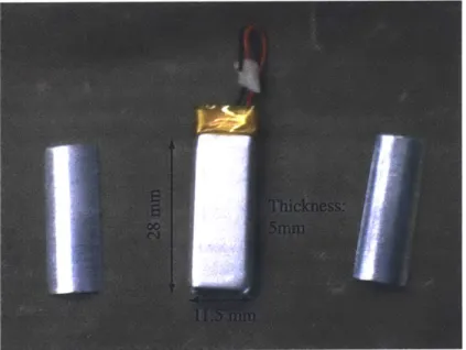
not able to tolerate large strains. In these situations, the use of a strain de-amplifier mechanism is desirable, in order to employ the high energy density of the active ma-terial in a more effective way. In addition, current lithium-ion cells have rectangular geometries and expand through their thickness (i.e., their short axis), which is not well suited for cases where in-plane actuation is desired, such as in the smart blade application. These considerations motivated the design of a coupling mechanism that could transform the through-thickness expansion of the cells into an in-plane mo-tion, while at the same time decreasing the free strain and increasing the stiffness of the actuator. The design was based on the geometry of the ATL (Amperex Tech-nology Limited, HK) 150 mAh battery, shown in Figure 2-12, and was named the Electrochemical Woven Actuator.
The concept of the woven actuator consists of enclosing each cell between two curved caps and creating a weave around them, in an alternating fashion. For elec-trochemical cells of small dimensions, the weaving could be done by a process similar to weaving on a loom. A schematic of the woven actuator concept is shown in Fig-ure 2-3, where it is seen that the vertical expansion of each cell draws the loops closer together, generating an in-plane contraction. Notice that the actuator requires a tensile preload to be able to generate motion in both directions, something that is desirable anyway to eliminate slack in the weave.
To test the concept, a prototype was built using steel wire instead of the intended ceramic fibers. The reasons for this decision were that steel wire is readily available and easier to manipulate by hand. It also facilitated the assembly process, as the
need for a curing step to embed the fibers in an epoxy matrix was avoided, where the high temperatures required could damage the cells. The steel-wire prototype was fully operational and the data obtained showed good agreement with the theoretical model, once we accounted for creep. The design, construction and testing of the prototype is described in the following subsections.
2.2.1
Actuator Design
The following figure shows a single unit of the actuator with the main design variables defined. The actuator geometry is described by the battery aspect ratio (t/w), total thickness (h), non-dimensional pitch (L/w) and battery length (B).
B
t h
L
Figure 2-4: Actuator unit with design variables defined.
To understand the relationships between these variables, a simplified model of the actuator was developed, based on the following assumptions:
1. The battery was modeled as a linear-elastic material in its entire range of
op-eration. This assumption means that, following the derivation presented in the previous chapter, the stress in the material is given by
where Ee is the modulus of the battery, cf is the cell free strain and 6 is the actual strain in the battery.
2. The stress on the battery was assumed to be evenly distributed across the entire surface. For a constant, low-curvature surface, and assuming that the wires behave like frictionless strings, it can be seen from a force balance at each differential string element that this uniform stress condition is satisfied.
3. The wire was assumed to have a uniform tension and its compliance was included
in the analysis as a source of mechanical losses.
4. The wire was required to be tangent to the surface of the cap to avoid stress concentrations, and its point of departure from the surface was located at the edge of the cap. This point was assumed to remain fixed during the entire range of motion.
5. No frictional or contact losses at the caps were included in the model.
We now obtain the model equations using these assumptions. Figure 2-5 show a sim-plified diagram of one actuator unit in the undeformed and deformed configurations, without the caps. The unit geometry is originally described by the quantities to, a0, bo and, in the activated and loaded state, by tL, aL, bL. The force and displacement in this state are denoted by QL and qL, respectively.
t
aLL
~q
L
QL
Figure 2-5: Actuating Unit before activation and after activation, under an external load. Note that the caps are not shown for clarity.
To compute the stress on the battery surface, using Equation 2.1, we have that the strain E at any configuration is given by
At
(2.2)
to
If we now take a free body diagram of one of the caps, as shown in Figure 2-6, it is found from a force balance that the total tension carried by the wires, T, is given by
2T sin9L = -Bw. (2.3)
This tension is related to the fiber elongation by using its spring stiffness KF, which takes into account the total wire length along the actuator unit LFO and the sum of the cross-sectional areas of all the wires covering its surface. We then have that
T = ALFKF- (2.4)
We can also relate T to the force that the actuator generates at its output, using the fact that
QL = 2T cos OL. (2.5)
Finally, the remaining equations are obtained by geometric considerations, giving that
qL = 2(ao - bL Cos OL) (2.6)
LFo
T #0_' _G_
OL 0L
bL = bo +AL (2-7)
2
sintLL = (2.8)
2bL
This set of equations can be solved for different values of the battery strain. Fig-ure 2-7 shows the predicted actuator characteristic curve, describing its displacement under different loads, for a battery with a modulus of 200 MPa and free strain of
1.5%, a wire diameter of 0.20 mm and L/w of 1.67, considering one actuating unit
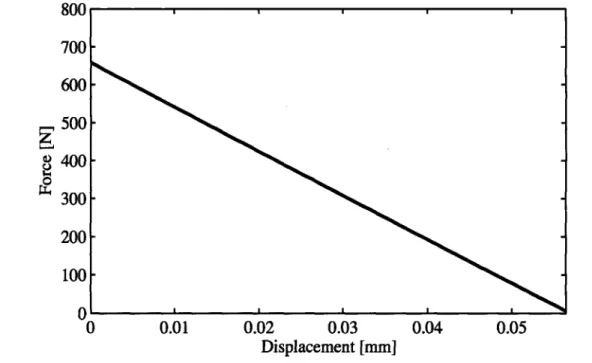
only. As we can see, the device behaves linearly in its entire range of operation, due to the small changes in the angle 0. The actuator properties for these particular design values are summarized on Table 2.1, and these values were used for the prototype construction. 800 700- 600- 500- 400- 300- 200- 100-0 0 0.01 0.02 0.03 0.04 0.05 Displacement [mm]
Figure 2-7: Load-displacement characteristic curve for a single unit of the Woven Actuator model.
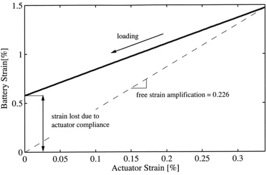
To gain more insight about the actuator behavior, we can plot the battery strain as a function of the actuator output strain, which varies according to the external load, as shown in Figure 2-8. Notice that at the right end of the curve we have the free strain condition, where a 0.34% actuator strain corresponds to 1.5% battery
Table 2.1: Results from Woven Actuator Model for a Single Unit (Ee = 200 MPa, cf
= 1.5%, wire diameter of 0.20 mm and L/w 1.67).
Property Predicted Value
Free Strain
(%)
0.34Stiffness (N/mm) 11,703
Blocked Force (N) 660
Energy Density (kJ/m3) 4.73
Mechanical Efficiency (%) 61.3
strain. This relation corresponds to a free strain amplification factor of 0.226. As the actuator load increases, for the same cell state of charge, the actuator output and battery strain decrease. For the blocked case, i.e. for an actuator output equal to 0, the battery strain is not 0, due to the compliance of the wires. Therefore, the wire compliance has the effect of reducing the mechanical energy seen at the actuator output. To quantify this effect, we define the mechanical efficiency as
I
7
mech =E E V (2.9)
2 f e
where V represents the total volume of the active elements in the actuator. For the prototype design, the mechanical efficiency was found to be 61.3%.
It can also be concluded from the model that the actuator properties have a strong dependence on the pitch of the device (L/w), as this pitch determines the value of the wire angle 00, which affects the free strain amplification factor. In Figure 2-9, the actuator stiffness and free strain are plotted as a function of this parameter. The plot shows that it is possible to select a value of L/w that corresponds to desired strain and stiffness values for any given application. However, in order to satisfy the tangency condition, the curvature of the surface needs to be increased as L/w approaches 1. This increase in L/w makes the actuator thicker, as shown in Figure 2-10, which is undesirable since it would be impractical to implement a thick actuator as an active weave concept and, in addition, the caps needed would be too heavy.
The effect of L/w on the actuator performance is shown in Figure 2-11, where the mechanical efficiency is plotted as a function of L/w. Notice that as L/w
ap-1.5 1 0.5 0 0 0.05 0.1 0.15 0.2 Actuator Strain [%]
Figure 2-8: Battery strain versus actuator output strain from the free strain condition to the blocked condition.
1400( 120C 840( 560( 280C 1.2 1.36 1.52 L/w 1.68 1.84 2 1.5 1.2 0. 9 0.3 0
Figure 2-9: Actuator stiffness and free strain as a function of L/w (one unit)
--free strain amplification = 0.226
strain lost due to actuator compliance / , 0.25 0.3 1 a.)
C-15
o-0
-1.2 1.3 1.4 1.5 1.6 1.7 1.8 1.9 2
L/w
Figure 2-10: Total actuator thickness as a function of L/w
proaches 1, the mechanical efficiency improves, as the smaller wire tension generates less compliance losses in the wire.2
2.2.2
Construction
The construction of the prototype involved two steps: (1) preparation of the battery-caps units and (2) weaving of the wire. The prototype consisted of three battery units, each of which had a set of aluminum caps bonded to their surfaces (see Figure 2-12). Its dimensions correspond to those of the design described in Table 2.1. The caps were machined by taking slices of a circular rod on a milling machine, although, for smaller dimensions and better precision, the preferred method would be to use a process such as wire electrodischarge machining (EDM). The caps were bonded to the battery surfaces using epoxy adhesive, which provides a strong bond, in order to prevent that possible shearing forces resulting from asymmetries in the loading generate a sliding motion, as occurred on earlier prototypes (see Figure 2-13).
2
0 0 0 0 100 80 60 40 20 1.2 1.3 1.4 1.5 1.6 1.7 1.8 1.9 2 L/w
Figure 2-11: Mechanical Efficiency of the Woven Actuator as function of L/w.
Figure 2-12: Lithium-ion battery with aluminum caps ready to be bonded
I I I I I I
Figure 2-13: Close-up of battery unit with improper cap bonding. Notice the sliding of the caps.
Once the battery units were ready, a wooden fixture was prepared to hold them for the weaving process (Figure 2-14). Notice that there was no need to maintain an accurate distance between the batteries at this point, as this would be adjusted through the tensioning of the wire. The weaving of the wire was done by hand, with two shackles placed at the ends of the actuator for holding it on the testing machine. We chose a wire diameter of 0.20 mm, based on considerations such as availability, load bearing and bending radius.
Considering the weave pattern of the actuator, as shown in Figure 2-15(left), one possible pattern consists of simply weaving the individual wires around the batteries, alternating from the upper surface of one battery to the lower surface of the next one. In this case, the weave formed at each cap only covers half of the total available surface, giving a total wire width of B/2. Alternatively, a better weaving pattern is shown in Figure 2-15(right) to consist of weaving the wires in pairs and, at the edges of the caps (where opposing pairs of wires meet), each pair is twisted in order to get a close packing. With this weaving technique, both surfaces are completely covered, giving a total wire width of B, which traduces into a smaller series compliance and a higher mechanical efficiency. In practice, this twisting consisted of a simple
crossing-Figure 2-14: Batteries with caps ready for weaving.
over of the wires at their intersecting brought to the right and vice-versa).
K
K
point (i.e., the wire initially on the left was
L
I
Figure 2-15: Comparison of 2 possible double-wire with twist weave (right).
wire pair crossover
K
weaving methods: single-wire weave (left) and
Figure 2-16 shows the completed actuator prototype. It is expected that, in the actual actuator, each fiber will constitute a separate strand that is bonded together at the ends of the actuator. For simplicity, this prototype was instead built out of
only two individual wires, running together around all the batteries, with the wire ends tied to the loops formed at one of the shackles.
Figure 2-16: Woven Actuator Sample close-up, ready for testing.
After the weaving was completed, the wiring was still loose and the battery units separation was bigger than the design value. The assembly was then subjected to a tensile load of 2,000 N by attaching a dummy weight and, in this condition, a series of short steel rods of different diameters were inserted at the ends of the actuator to

![Figure 1-3: Schematic of micromachined cell with highly oriented pyrolitic graphite (HOPG) and picture of load-bearing posts (reproduced from [7])](https://thumb-eu.123doks.com/thumbv2/123doknet/14732627.573374/23.918.186.724.151.351/figure-schematic-micromachined-oriented-pyrolitic-graphite-picture-reproduced.webp)
![Figure 1-4: Laminated actuators made of LiCoO 2 and graphite electrodes, in a design similar to current commercial batteries (from [7]).](https://thumb-eu.123doks.com/thumbv2/123doknet/14732627.573374/24.918.272.609.130.442/figure-laminated-actuators-graphite-electrodes-similar-commercial-batteries.webp)
![Figure 1-5: Comparison of first-generation electrochemical actuators with other active material technologies (based on [11]).](https://thumb-eu.123doks.com/thumbv2/123doknet/14732627.573374/25.918.154.775.358.800/figure-comparison-generation-electrochemical-actuators-active-material-technologies.webp)