Designs for the Manufacture of Manipulable
Plastic DNA/RNA Building Blocks for Learning
ACaiVELife Science
by
Bethany I. Lemanski
IT73 ACS OF- TE-C!NOLOGYTT INSITUTE
JUL 3
1
2013
LIBRARIES
Submitted to the Department of Mechanical Engineering
in partial fulfillment of the requirements for the degree of
Bachelor of Science in Mechanical Engineering
at the
MASSACHUSETTS INSTITUTE OF TECHNOLOGY
June 2013
©
Bethany I. Lemanski, MMXIII. All rights reserved.
The author hereby grants to MIT permission to reproduce and to
distribute publicly paper and electronic copies of this thesis document
in whole or in part in any medium now known or hereafter created.
A uthor ...
Department of Mechanical Engineering
AMay 10, 2013Certified by ...
....
*...
.
/
J. Kim Vandiver
Dean for Undergraduate Research
Thesis Supervisor
Accepted by ...
Annette Hosoi
Professor of Mechanical Engineering
Undergraduate Officer
Designs for the Manufacture of Manipulable Plastic
DNA/RNA Building Blocks for Learning Life Science
by
Bethany I. Lemanski
Submitted to the Department of Mechanical Engineering on May 10, 2013, in partial fulfillment of the
requirements for the degree of
Bachelor of Science in Mechanical Engineering
Abstract
The subject of this thesis is the design of custom injection-molded manipulable DNA building blocks for use in a hands-on life sciences educational kit. The new design of the DNA building blocks is meant to replace the existing building blocks, which are hand-constructed from 12 existing LEGO@ blocks and glued together by volunteers. The goals of the new design are to reduce the part count, increase the ease of assembly and outsource it to the end-user, and reduce dependence on the availability of LEGO components without sacrificing function and while keeping mold and production costs low. The functional requirements for the building blocks were determined through detailed conversations with the designer of the existing LEGO DNA Learning Center Set and its supplementary curriculum materials. Simple mechanical models and 3D-printed prototypes were used in an iterative design process. The part count for each building block was reduced to 3, which require 6 unique molds. Several design options for each of the three subcomponents of the DNA building blocks are presented for further assessment of mold cost and manufacturability.
Thesis Supervisor: J. Kim Vandiver Title: Dean for Undergraduate Research
Acknowledgments
I would like to thank Professor J. Kim Vandiver and Dr. Kathy Vandiver for their
incredible insights and support. It has been a wonderful and unique experience work-ing so closely with such dedicated and talented individuals. I would especially like to thank Professor Vandiver, who is also my academic advisor, for taking the time to discuss my professional interests and for offering me the opportunity to work on this project when he realized it would be suitable. Moreover, I would like to thank Professor Vandiver for offering so much of his personal time to work one-on-one with me. His engineering intuition and excitement for teaching and outreach is refreshing and inspiring. Lastly, I would like to thank James Penn and Professor David Wallace for sharing their 3D printer and time with us so we could efficiently and effectively develop many iterations of prototypes.
Contents
1 Introduction 19
2 Functional Requirements 21
2.1 The Educational Objectives . . . . 23
2.1.1 Understanding the Composition of a Nucleotide . . . . 23
2.1.2 Understanding the Primary Structure of a Nucleic Acid Strand 24 2.1.3 Understanding the Secondary Structure of DNA . . . . 25
2.1.4 Understanding Base-Pairing . . . . 26
2.1.5 Understanding DNA Replication and mRNA Transcription . . 27
2.2 Assembly Considerations . . . . 28
2.3 Lessons from the Previous Design . . . . 29
3 Design Approach 33 3.1 Overall Form Factor . . . . 33
3.2 Design M odules . . . . 36
3.2.1 Phosphate Bond . . . . 36
3.2.2 Hydrogen Bond . . . . 44
3.2.3 Base-Sugar Bond . . . . 55
3.2.4 Base and Sugar Structural Design . . . . 59
4 Current Design and Future Work 63 4.1 Status of the Design . . . . 63
4.1.2 4.1.3 4.1.4 4.2 Next 4.2.1 4.2.2 4.2.3
A Detailed Engineering Drawings
B Final Geometry Force and Strain Calculations
Sugar Component . . . . Base Components . . . . Nucleotide Assembly . . . . . Steps . . . .
Finalizing Dimensions .
Mold Cost Analysis . . . . Manufacturing Considerations . . . . 6 5 . . . . 6 6 . . . . 6 6 . . . . 6 8 . . . . 6 8 . . . . 7 0 . . . . 7 1 73 89
List of Figures
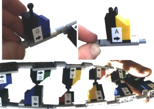
2-1 Photographs of the DNA nucleotide components in the LEGO DNA Learning Center Set. @The LEGO Group and MIT. LEGO, the LEGO logo, and the brick and knob configuration are trademarks of the LEGO
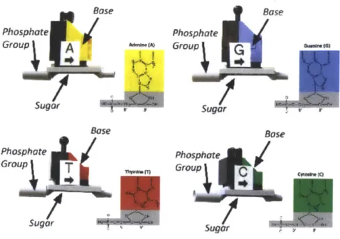
Group. All Rights Reserved. Photographs by author. . . . . 22 2-2 Pictures of the LEGO DNA nucleotides with color-coded diagrams of
the corresponding chemical molecular structure. Diagram replicated from LEGO DNA Learning Center Set curriculum materials.[12] . 24
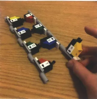
2-3 A photo showing the DNA strands lying flat on a desk, with a
sin-gle nucleotide twisted upward. This degree of freedom is crucial for teaching purposes. . . . .. . . . . 26
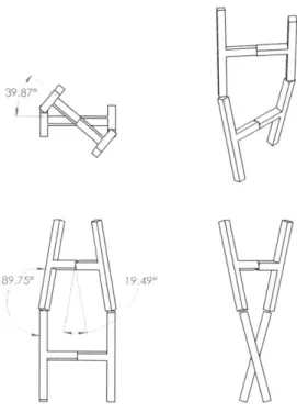
2-4 A diagram demonstrating the rotational degrees of freedom needed to create the helix geometry. A simplified ladder structure is shown from several angles, showing approximate angular rotation values needed. . 27 2-5 A diagram of the basis definitions for the local coordinate reference
frames for the hydrogen bond and phosphate-sugar bond joints used in defining the desired degrees of freedom in table 2.2. The 1-2-3 basis is the local reference frame for the hydrogen bond joint and the 4-5-6
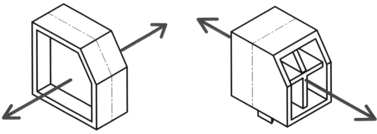
basis is the local reference frame for the phosphate-sugar bond. . . . 30 3-1 A diagram of the two basic designs resulting from the two directions
of draw considered for the molding process. The design shown on left was ultimately chosen and pursued throughout the remaining design process. . . . . 34
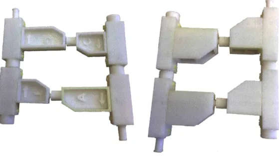
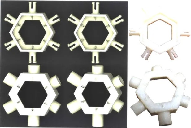
3-2 Photographs of the two basic form factors prototyped by 3D printing. The form actor on the left was ultimately chosen. Photographs by author. ... ... ... . ... 35
3-3 A diagram showing the three different aspect ratios considered for the
base form factor, where x, Y1, Y2 are approximately the dimensions of the previous LEGO DNA building block design. Not to scale. The size scale shown on the far right was ultimately chosen. . . . . 35
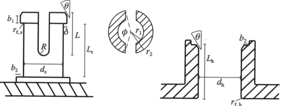
3-4 Left: A diagram of the side view of the male phosphate connector with relevant dimensions labeled. Middle: A diagram of the top view of the male phosphate connector with cross-sectional dimensions labeled. Right: A diagram of the side view of the female phosphate connector with relevant dimensions labeled. . . . . 37
3-5 Left: A diagram of the geometry factor, K1 as a function of the ratio
of inner and outer radii of a constant annular cross section cantilever beam loaded at the tip for different angles subtended by the annulus. Right: A diagram of the section modulus, Z1 as a function of the ratio
of inner and outer radii of a constant annular cross section cantilever beam loaded at the tip for different angles subtended by the annulus. Assumes concave side of annulus under tension.[10] . . . . 38
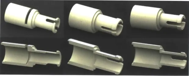
3-6 From left to right, a progression of the Phosphate component proto-types. The first iteration used a slot to create a true snap-fit latch. The second and third iterations excluded this feature, creating a hy-brid snap-friction fit. The second iteration (middle) tested a larger
3-7 Top from left: a CAD rendering of the prototype platform for the first
six iterations of the male phosphate connector; a CAD rendering of the prototype platform for the next six iterations of the male phosphate connector; a photograph of one of the 3D printed prototype platforms for male phosphate connector. Bottom from left: a CAD rendering of the prototype platform for the first six iterations of the female phos-phate connector; a CAD rendering of the prototype platform for the next six iterations of the female phosphate connector; a photograph of one of the 3D printed prototype platforms for female phosphate connector. Photographs by author. . . . . 41
3-8 Left: A free body diagram of the forces on the male phosphate con-nector during assembly, where
f
is the normal contact force, [ is thecoefficient of friction, and Wasm is the assembly force. Right: A free body diagram of the forces onthe male phosphate connector during disassembly of the joint, where Wdi, is the disassembly force. . . . . . 43
3-9 Left: The first set of six iterations of the female hydrogen bond joint, where different types of joint and different assembly and release mecha-nisms were considered. Right: The corresponding set of male hydrogen bond joints. . . . . 45
3-10 Top left: A diagram of the male hydrogen bond connector used in
models of the joint with relevant dimensions labeled. Top right: A diagram of the female hydrogen bond connector used in models of the joint with relevant dimensions labeled. Bottom: a top view of the cross section of the female bond with 4 cantilevers (left) and 6 cantilevers (right). . . . . 47
3-11 Left: A diagram of the geometry factor, K2 as a function of the ratio of inner and outer radii of a constant annular cross section cantilever beam loaded at the tip for different angles subtended by the annulus. Right: A diagram of the section modulus, Z2 as a function of the ratio
of inner and outer radii of a constant annular cross section cantilever beam loaded at the tip for different angles subtended by the annulus. Assumes convex side of annulus under tension.[10] . . . . 48
3-12 Top from left: a CAD rendering of the prototype platform for the
second six iterations of the male hydrogen bond connector; a CAD rendering of the prototype platform for the next six iterations of the male hydrogen bond connector; a photograph of one of the 3D printed prototype platforms for the male hydrogen bond connector. Bottom from left: a CAD rendering of the prototype platform for the second six iterations of the female hydrogen bond connector; a CAD rendering of the prototype platform for the next six iterations of the female hydro-gen bond connector; a photograph of one of the 3D printed prototype platforms for female hydrogen bond connector. Photographs by author. 49
3-13 A photograph of one of the sets of female hydrogen bond connectors
after repeated assembly and disassembly led to fracture at the base of the cantilever joints. Fracture originated at the base near the radii, where the stress concentration is highest and propogated at 450 angles, marked by red lines in the image. Fast fracture suggests that the cantilevers were overstrained, not fatigued. Photograph by author. 50
3-14 A diagram of the five geometries of the male hydrogen bond connectors considered. The cantilever acts as a fulcrum, causing the rest of the connector to pivot about a point. The path of the connector is shown as a curve in red, with a dashed line pointing to the instantaneous center of rotation. Under this release mechanism, the deflection 6 can be much larger than the deflection 6 occuring in the straight release
3-15 A later set of hydrogen bond prototypes that takes the fulcrum effect
into account. Left: CAD rendering of a set of three male connector prototypes and six female connector prototypes. Right: A set of proto-types that also explores the effect of changing the cross-sectional profile of the cantilever and increasing the number of cantilevers, still taking the fulcrum effect into account. . . . . 52 3-16 Top left and right: Free body diagrams of the female hydrogen bond
joint during assembly in the two planes, assuming four cantilevers. Bottom left and right: Free body diagrams of the male hydrogen bond joint during assembly in the two planes. W is the assembly force,
f
is the contact force, and mu is the friction coefficient. . . . . 543-17 Left: A diagram of the male sugar-base 'latch' with relevant dimensions
labeled. Right: a diagram of the female sugar-base connector with relevant dimensions labeled. . . . . 55 3-18 A free body diagram of the male sugar-base latch during assembly.
W is the assembly force,
f
is the contact force, and p is the friction coefficient. . . . . 56 3-19 A diagram comparing the effect of changing the relative fillet radiusat the base of the latch, R1 and at the top of the connection hub,
Rh-When Rh < R1 (left), the base of the latch does not rest flat against
the top surface of the hub, unlike when Rh > R1 (right) . . . . 57 3-20 Left and Middle: CAD renderings of prototypes of the male (top)
and female (bottom) connectors for the sugar-base latch. Right: Pho-tographs of a 3D-printed prototype of the male (top) and female (bot-tom ) platform s. . . . . 58 3-21 CAD rendering of the structural form for the base component.
3-22 From left to right: CAD renderings of the progression of prototypes
for the sugar component (top view on top row, bottom or section view on bottom row): Curved walls and a recessed top surface add stiffness and asymmetry, respectively. Ribs on the bottom surface serve a dual purpose of providing stiffness and acting as the hub for the sugar-base latch.. . . .. ... . . . .. . . . .. . . . . 60
4-1 Left: CAD renderings of phosphate group design option 1 for the phos-phate component, side (top) and section (bottom) views. Utilizes two constant cross-section annular cantilevers. Right: CAD renderings of phosphate group design option 2 for the phosphate component, side (top) and section (bottom) views. Utilizes two tapered cross-section annular cantilevers. . . . . 64 4-2 Left: CAD rendering of sugar design option 1, in which the phosphate
connector uses two constant cross-section annular cantilevers. Right:
CAD rendering of sugar design option 2, in which the phosphate
con-nector uses two tapered cross-section annular cantilevers. . . . . 65
4-3 CAD renderings of the bases that utilize male hydrogen bond connec-tors. Left: Thymine. Right: Guanine. . . . . 67
4-4 CAD renderings of the two design options for the bases that utilize female hydrogen bond connectors (Adenine and Cytosine). Left: fe-male hydrogen bond design option 1 utilizes four tapered cross-section cantilevers. Right: female hydrogen bond design option 2 utilizes six constant cross-section cantilevers. . . . . 67
4-5 A CAD rendering of the three separate components that comprise a single nucleotide in the new design: the phosphate (darkest gray), sugar (light gray), and base (blue). The red arrows show how the phosphate and base are assembled onto the sugar. . . . . 68
4-6 CAD renderings of the four different nucleotide assemblies using the sugar, phosphate, and base design option 1. . . . . 69
4-7 CAD rendering of a sample assembled DNA strand using the sugar, phosphate, and base design option 1. . . . . 70
List of Tables
2.1 A summary of the functional requirements determined from
conversa-tions with the clients. . . . . 31
2.2 A summary of the required degrees of freedom for each joint. Refer to
figure 2-5 for a definition of the local vector bases for each joint. . . . 32 2.3 A summary of additional engineering specifications: assembly and
dis-assem bly forces. . . . . 32
B. 1 Equations and values used to estimate force and strain for final ge-ometries of the hydrogen bond joint. Force and strain are conservative values. Values of the target maximal strain, secant modulus, and fric-tion angle are taken from a Snap-Fit design guide.
[2]
. . . . 90B.2 Equations and values used to estimate force and strain for final geome-tries of the phosphate bond joint. Force and strain are conservative values. Values of the target maximal strain, secant modulus, and fric-tion angle are taken from a Snap-Fit design guide.
[2]
. . . . 91 B.3 Equations and values used to estimate force and strain for finalgeome-tries of the sugar-base latch. Force and strain are conservative values. Values of the target maximal strain, secant modulus, and friction angle
Chapter 1
Introduction
The Mind and Hand Alliance, a program organized through the MIT Edgerton Cen-ter, develops hands-on educational materials for teaching science, technology, engi-neering, and mathematics (STEM) in K-12 education.[7] One of the curriculum tools developed by the program is the LEGO® DNA Learning Center Set, which includes a kit of small plastic manipulable DNA and mRNA building blocks. The plastic building blocks are designed to teach what the molecules do by allowing students to physically perform the cell functions (DNA replication, mRNA transcription, and tRNA translation), reinforcing the theoretical concepts through a hands-on process of self-discovery.
There are two main problems with the existing DNA Learning Kit. First of all, the assembly process is too time consuming and labor-intensive. Currently, the building blocks in each kit are pre-assembled from 9-12 existing LEGO pieces and glued together by community volunteers. By one estimate, each classroom set of 14 DNA/RNA kits takes approximately 50 man-hours to assemble.[11] This esti-mate does not include the time-consuming process of quality control, during which each piece must be double-checked to ensure that it was assembled properly, since many steps of the assembly process are ambiguous. Moreover, because the current
DNA/RNA building blocks are made entirely from existing LEGO components, the
resultant design is constrained by the geometries of the available LEGO blocks. The
have recently been discontinued, and since the behavior of the Hydrogen bond is in-tegral to the function of DNA and RNA, these blocks cannot easily be replaced by other existing blocks.
This second problem in particular has motivated Professor J. Kim Vandiver, fac-ulty director of the Edgerton Center, and Dr. Kathy Vandiver, the Edgerton Center's primary K-12 curriculum developer, to explore alternative ways of manufacturing the
DNA/ RNA building block pieces. The goal of this thesis project is to redesign the DNA/ RNA building block pieces such that they can be custom injection-molded
and end-user assembled, thereby eliminating the time-consuming pre-assembly pro-cess and the reliance on available LEGO products. In addition to this document, the outcome of this thesis is a set of CAD models of the proposed design and cost estimates for manufacturing the molds and carrying out low volume short run pro-duction.
The approach adopted to solve this design problem was as follows. First, the functional requirements for the building blocks were determined through detailed conversations with the clients, Professor J. Kim Vandiver and Dr. Kathy Vandiver. Dr. Kathy Vandiver, the designer of the current LEGO DNA Learning Center Set and its supplementary curriculum materials, is intimately familiar with the classroom use of the DNA/RNA learning kit as well as the desired educational outcomes. As such, she served as an indispensable source of background knowledge, constructive criticism, and insight into how design decisions would fare in the classroom. Next, best practices for designing injection molded pieces were researched. With these best practices and functional requirements in mind, the theoretical minimum number of sub-components was determined and a set of possible design options for overall form was proposed. Once an overall form was chosen by the clients, the design was partitioned into functional design modules. Design options for each module were brainstormed and prototyped by 3D printing. After an iterative prototyping process guided by feedback from the clients and simple mechanical models, a set of suggested design options is proposed for soliciting cost estimates from vendors.
Chapter 2
Functional Requirements
One of the main ways that the LEGO DNA Learning Center Set differs from other ed-ucational DNA models is that it teaches students how DNA works by allowing them to physically engage with the kit. Whereas other educational DNA models often strive to serve as visual representations of the molecular form of DNA, the LEGO DNA Learn-ing Center Set strives to provide an interactive demonstration of the macromolecular functions of DNA. As such, the molecular structure is intentionally abstracted, while the functional relationships between macromolecules are emphasized. Consequently, the functional requirements for the design of the DNA building blocks must reflect an understanding of how the basic structure of the macromolecular components of
DNA function in DNA replication and mRNA transcription, as well as how these
concepts are taught using the kit. To learn more about the educational objectives, I spoke with Dr. Kathy Vandiver, the expert curriculum developer for the Mind and Hand Alliance and designer of the current DNA Learning Kit. The resulting func-tional requirements, desired degrees of freedom, and engineering specifications are summarized in tables 2.1, 2.2, and 2.3 respectively, and are explained in the follow-ing section. For reference, the buildfollow-ing blocks in the current DNA Learnfollow-ing Kit are shown in figure 2-1.
Figure 2-1: Photographs of the DNA nucleotide components in the LEGO DNA Learning Center Set. @The LEGO Group and MIT. LEGO, the LEGO logo, and the brick and knob configuration are trademarks of the LEGO Group. All Rights Reserved. Photographs by author.
2.1
The Educational Objectives
From using the DNA/RNA kit in the DNA Learning Center Set, students should understand the three main sub-molecules that comprise a nucleotide, the difference between RNA and DNA, the primary structure of each DNA and RNA strand in-cluding its inherent asymmetry, and the secondary structure of DNA that results in a double-helix comprised of two strands with opposite directionalities. They should also learn about unique base-pairing, the semi-conservative process of DNA replication, and the transcription of DNA into mRNA.[12]
2.1.1 Understanding the Composition of a Nucleotide
In order to help the students identify the three distinct types of sub-molecules that comprise a nucleotide, which are the sugar, the phosphate group, and the base, the plastic DNA/RNA building blocks should be comprised of three distinct parts which
are differentiated either by shape, color, or both. Students should be able to distin-guish between different variations of each type of sub-molecule while still recognizing them as the same type of molecule. For example, students must be able to distin-guish the sugar in RNA from the sugar in DNA, while recognizing that they are both sugar molecules. Similarly, students should be able to distinguish between Adenine, Guanine, Thymine, Cytosine, and Uracil while recognizing that these are all bases. Moreover, students should be able to distinguish between Purines and Pyrimidines, the two different base geometries. As such, parts that represent the same category of molecule should have a similar overall form but with easily recognizable variations. The proposed method of accomplishing this is similar to the existing method: by using the same general form but changing the plastic color. This is an abstraction meant to help students easily visualize the important differences and similarities while working with the building blocks. It also greatly reduces the manufacturing costs, since a single mold can be used with different color plastics instead of requiring unique molds. Figure 2-2 is from the curriculum guide for the current DNA Learning Kit, which shows how the current design is used to abstract the molecules.[12]
Base Base
Phosphate Phosphate
Group
A
GroupG**IG)
Sugar Sugar Base Bose Phosphate Phosphate Group
T
Group C Sugar SugorFigure 2-2: Pictures of the LEGO DNA nucleotides with color-coded diagrams of the corresponding chemical molecular structure. Diagram replicated from LEGO DNA Learning Center Set curriculum materials. [12]
2.1.2
Understanding the Primary Structure of a Nucleic Acid
Strand
The important aspects of the primary structure of nucleic acid strands that students are expected to understand are that each nucleotide is asymmetric and that the phosphate group on the 5' end of the sugar bonds covalently to the 3' end of a neighboring sugar, allowing nucleotides to create a sugar-phosphate "backbone." This implies that for the plastic DNA/RNA building blocks, the sugar piece should be asymmetric, with a distinguishable 3' end and 5' end. Furthermore, the 5' end of the sugar should join permanently to a phosphate group, which should join tightly but reversibly to the 3' end of a sugar. In an abstract sense, both the sugar and the phosphate should have a female connector and a male connector on opposite ends. In addition, since nucleotides are usually found loose in the nucleus with two extra phosphate groups attached, the male end of the phosphate group should be able to join tightly but reversibly to the female end of another phosphate group. Logically, this
means that both the male connector on the phosphate group and the male connector on the sugar should be able to join tightly but reversibly to the female connector of the phosphate group, while the male connector of the phosphate should be able to join permanently to the female connector of the sugar.
2.1.3
Understanding the Secondary Structure of DNA
The important aspects of the secondary structure of DNA that students should learn are that hydrogen bonds between base pairs weakly connect two DNA strands to-gether, that the two strands are identical but oppositely oriented, and that the strands can coil and form a double helix. For teaching purposes, the strands must also be able to unfold and lay flat so that students can easily work with the building blocks on a desk. Students should be able to perceive the difference in strength between the hy-drogen bonds formed through base-pairing and the covalent sugar-phosphate bonds. They should learn that because the hydrogen bond is about 10 times weaker than the covalent bond, the two DNA strands easily separate or "unzip" to allow DNA
replication or mRNA transcription to occur. This means that the retention force in the joint representing the hydrogen bond should be around 5-10 times smaller than the retention force in the joint representing the sugar-phosphate bond. Furthermore, if possible, the two types of joints should be visibly distinguishable to help reiterate the difference in the nature of the bonds.
The geometry of the double helix also determines the desired degrees of freedom for both the joint representing the phosphate-sugar bond and the joint representing the hydrogen bond. Figure 2-4 shows an abstraction of the DNA geometry to help visualize the degrees of freedom that enable a double helix. These are also stated mathematically in table 2.1. Practical considerations put additional constraints on the desired degrees of freedom, however. For teaching purposes, it is desirable to be able to rotate an individual nucleotide up to 1800 in either direction along the axis of the backbone while the strands are laid out flat (see figure 2-3 ). In addition, it is desirable to be able to detach a single hydrogen bond while the other hydrogen bonds remain attached. Thus, a hydrogen bond should be able to disconnect by rotating
Figure 2-3: A photo showing the DNA strands lying flat on a desk, with a single nucleotide twisted upward. This degree of freedom is crucial for teaching purposes. the nucleotide about the axis perpendicular to the plane containing the two DNA strands.
2.1.4
Understanding Base-Pairing
One of the most important concepts that students are meant to discover while using the DNA Learning Center Set is how base-pairing enables DNA to transmit a unique code. To understand this, students must first understand that there are two kinds of bases, purines and pyrimidines, which are different sizes. Thus a unique base pair must consist of one purine (Guanine or Adenine), which is a longer molecule, and one pyrimidine (Cytosine or Thymine), a shorter molecule, in order to keep the distance between DNA strands constant, which is necessary to properly form the parallel sugar-phosphate backbone. Furthermore, Guanine should only be able to bond with Cytosine and Thymine should only be able to bond with Adenine in order for the hydrogen bonds to line up properly. Currently, there are male connectors and female connectors to demonstrate the favorable bonding configurations. Thus, each base is actually abstracted as a unique combination of two options for the two emphasized features, the base size and the bond configuration: Adenine is long with a female
i
39.870
189.750 19 490
Figure 2-4: A diagram demonstrating the rotational degrees of freedom needed to create the helix geometry. A simplified ladder structure is shown from several angles, showing approximate angular rotation values needed.
bond, Guanine is long with a male bond, Thymine is short with a male bond and Cytosine is short with a female bond.
2.1.5
Understanding DNA Replication and mRNA
Transcrip-tion
An important principle that students are meant to learn by using the kit is that
DNA replication is a semi-conservative process. This means that each new set of DNA contains one old strand and one new strand. Thus, for teaching purposes, it
is important for students to be able to track the original strands of DNA as they go through the replication process. In designing the plastic nucleotide components, there should be a way to attach a marker to the sugar as a way of flagging the original strands. This marker can also later be used in more advanced discussions of transcription and gene expression.
Students can also learn the process of mRNA transcription with the kit. For this to be effective, the only differences between the RNA nucleotides and DNA nucleotides should be a different color sugar, and the Uracil base component should be the same shape but a different color from the Thymine base component. Other than that, all other components should remain the same.
2.2
Assembly Considerations
The clients' ultimate goal is to eliminate the volunteer assembly process and rely instead on the end-user to complete assembly. Instead of receiving a box of pre-assembled nucleotides, classrooms will receive an organized box of sub-components, which can then be assembled by the class the first time the kit is used. In order to make this feasible, assembly must be as simple as possible. Each DNA building block should be comprised of the minimum possible number of sub-components and should be impossible to assemble improperly. For example, one common mistake that volunteer assemblers make with the current design is they incorrectly orient the base, which is intentionally asymmetric to reflect the asymmetry of the molecule. This can cause great confusion during the learning process if it is not caught before the kit is sent out. Thus, asymmetric components should have asymmetric attachments, so they cannot be assembled in the wrong orientation. Moreover, the joints representing different types of bonds should not be able to join together, so that students do not accidentally improperly assemble the DNA strands from the DNA building blocks, since the giving students the ability to learn through trial-and-error is what gives the kit its greatest educational value.
Currently, each base is labeled with the appropriate letter C, G, A, or T and an arrow indicating the directionality. This is important so that students learn the base pairing by name and not simply by color or shape. Each sugar is also labeled with a
3' on one end to distinguish the 3' and 5' ends. These markings require sticker labels
to be printed and placed individually in the proper orientation on each assembled
include the letters molded directly into the base and sugar components so that no additional post-processing is needed.
Since the learning objectives are dependent on students being able to take apart strands of DNA but not the nucleotides themselves, it is undesirable for each DNA building block to be easily disassembled by hand. In the current design, the existing
LEGO blocks are glued together by the volunteer assemblers to prevent the blocks
from coming apart, since out-of-the-box LEGO blocks are meant to be repeatedly assembled and disassembled. The new DNA building blocks should be designed such that permanent connections can be made without glue, such as by using a permanent snap-fits. Thus, while the class will have to put together the individual nucleotides the first time they receive the kit, they will not be able to disassemble them thereafter without the use of special tools.
2.3
Lessons from the Previous Design
Probably the most valuable asset in the design of the new DNA Learning Kit building blocks is the previous design, shown in figure 2-1. Since the previous design has been in use in classrooms for several years now, the clients have great insight into what does and does not work well with the current design. As such, the current design was used both as a guide and as a basis of comparison for evaluating the new design.
As shown in the figure, the previous design of each nucleotide consists of 9-12
LEGO subcomponents. The sugar-phosphate bond is accomplished by a snap-fit
cantilever latch with a flexible shaft. Currently, the male component of the latch is glued to one side of the sugar to make the connection permanent. The hydrogen bond is achieved through a ball-and-socket joint that LEGO has now discontinued.
A favorable property of the hydrogen bond joint is its ability to 'pop' open when the
joint is bent slightly out of plane. The current design is clearly a masterful feat of engineering using existing off-the-shelf LEGO components. Yet, since the design was constrained by a limited set of pre-existing building blocks, an important part of this design process is evaluating the strengths and weaknesses of the previous design.
e
6e2
1
Figure 2-5: A diagram of the basis definitions for the local coordinate reference frames for the hydrogen bond and phosphate-sugar bond joints used in defining the desired degrees of freedom in table 2.2. The 1-2-3 basis is the local reference frame for the hydrogen bond joint and the 4-5-6 basis is the local reference frame for the
phosphate-sugar bond.
Geometrically, the current design meets all the required degrees of freedom. The hydrogen bond joint actually has a rotational range of motion greater than needed to create the helix, which causes nucleotides to bend out of plane unnecessarily. However, some bending out of plane is desirable because it allows users to release a single hydrogen bond in a long strand without disconnecting any other pieces. Moreover, through use in the classroom, Dr. Kathy Vandiver discovered that a bending release mechanism is desirable for the hydrogen bond joint. Although the clients assert that the current design does not fatigue easily, they noted that the part of the current design that is most prone to fatigue is the neck of ball, which serves as the male connector for the hydrogen bond, shown on the top left in figure 2-1.
Generally speaking, the clients like the overall form of the current design. However, they both expressed a desire to make the design smaller and flatter so that longer
DNA strands could be made on a single student desk and so that the kit components
Table 2.1: A summary of the functional requirements determined from conversations with the clients.
Functional Requirements
Members of the same type of molecule should be identifiable as the same type of molecule, but should be easily distinguishable as different variations
Purines should be longer than Pyramidines
Each nucleotide should have a distinguishable 3' end and 5' end Phosphate groups should bond permanently to the 5' end of the sugar Phosphate groups should bond reversibly to the 3' end of the sugar
Sugar components should not be able to bond permanently to other sugar components in the event of misassembly
Covalent sugar-phosphate bonds should be stronger than base-base hydrogen bonds Double- stranded DNA should be able to form a helix or lay flat on a table
Individual nucleotides should be able to be isolated and rotated outwards hydrogen bonds should be able to be disconnected by bending out of plane
Students should be able to feel that the hydrogen bond is weaker than the phosphate-sugar bond (see Table 2.3 for joint force specifications.
Students should be able to visually distinguish hydrogen bonds from phosphate-sugar bonds
Base components should not be able to latch to sugar components in the wrong orientation
Permanent attachments should not require glue or external materials/tools
DNA strands should be able to be repeatedly assembled and disassembled without
any permanent deformation or damage to individual blocks The original DNA strands should be able to be flagged or marked Text and arrows should be molded into the components
Table 2.2: A summary of the required degrees of freedom for each joint. Refer to figure 2-5 for a definition of the local vector bases for each joint.
Degree of Freedom Range of Values
Hydrogen Bond Joint: rotation about ei [-1800, 18001
Hydrogen Bond Joint: rotation about e2 [-150, 150]; beyond ±150 is a mode of
re-lease
Hydrogen Bond Joint: rotation about e3 [-150, 150]; beyond ±150 is a mode of
re-lease
Hydrogen Bond Joint: translation in el < ±0.008 in; beyond ±0.008 in is a mode
of release
Hydrogen Bond Joint: translation in e2 < ±0.004 in (effectively constrained)
Hydrogen Bond Joint: translation in e3 < ±0.004 in (effectively constrained)
Phosphate Bond Joint: rotation about e4 [-1800, 1800]
Phosphate Bond Joint: rotation about e5 [-100, 100]
Phosphate Bond Joint: rotation about e6 [-100, 1001
Phosphate Bond Joint (3' to Phosphate): unconstrained; mode of release translation in e4
Phosphate Bond Joint (3' to Phosphate): constrained translation e5
Phosphate Bond Joint (3' to Phosphate): constrained translation e6
Phosphate Bond Joint (Phosphate to 5'): < ±0.004 in (effectively constrained)
translation in e4
Phosphate Bond Joint (Phosphate to 5'): < ±0.004 in (effectively constrained)
translation e5
Phosphate Bond Joint (Phosphate to 5'): < ±0.004 in (effectively constrained)
translation e6
Table 2.3: A summary of additional engineering specifications: assembly and disas-sembly forces.
Engineering Specification Value
Hydrogen Bond Joint: assembly force Fasm 1 N Hydrogen Bond Joint: disassembly force Fi, I iN
Phosphate Bond Joint: assembly force Fasm ~ 5 - 10 N
Chapter 3
Design Approach
After determining the functional requirements and researching basic injection molding Design For Manufacture (DFM) principles, it is suggested that each DNA building block be molded as three separate pieces that are permanently assembled. Based on the functional requirements, the most natural and simple proposal is to mold the sugar, phosphate group, and bases as separate components that are end-user assembled. This will require a total of six different molds: four for each of the bases and one each for the phosphate group and the sugar.
3.1
Overall Form Factor
The next step in this design approach was to determine the direction of draw from the mold, which limits the overall form factor of the components due to constraints of the injection molding process.
Two directions of draw were considered for the base component: along the axis perpendicular to the plane containing the DNA strands or along the axis of the DNA strands, as shown in the diagram in figure 3-1. In the figure, the gray arrows point along the direction that the two halves of the mold will separate (i.e. the direction of draw). The dashed line represents the parting line, where the two halves of the mold come together. One of the most important guidelines in designing injection molded parts is to keep wall thickness small and uniform as much as possible. This is because
Figure 3-1: A diagram of the two basic designs resulting from the two directions of draw considered for the molding process. The design shown on left was ultimately chosen and pursued throughout the remaining design process.
the cooling time of the molded part is proportional to the thickness squared, which means thicker walls will cool significantly more slowly than thinner walls.[9] Uneven wall thickness can lead to warpage and voids. [8][1] With the wall thickness limitation in mind, two different form factors were proposed, shown in figure 3-1.
For the sugar component, only one direction of draw was considered: the axis along which the base connects to the sugar. This direction of draw was chosen because it makes the design of an attachment mechanism between the base and sugar the easiest. Moreover, it allows for "3' " and/or "5' " labels to be molded into.the top surface of the sugar, which is how the current building blocks are labeled.
Prototypes of each form factor were fabricated by 3D printing, as shown in figure
3-2. Ultimately, the client decided to go with the first form factor option, shown on
the left in the figure, for two main reasons. First of all, since text can only be molded on surfaces perpendicular to the direction of draw, only the first option allows for letter labels and arrows to be directly molded onto an easily visible surface. Secondly, the first form factor is more symmetric, which makes the design more aesthetically pleasing both when the pieces are lying flat on the table and when they are held up
as a helix.
Before detailed design was carried out, an approximate size scale and aspect ratio was determined. Based on discussions with the client, the desired size scale is on
Figure 3-2: Photographs of the two basic form factors prototyped by 3D printing. The form actor on the left was ultimately chosen. Photographs by author.
the order of the current design, or preferably slightly smaller. Prototypes of different size scales and aspect ratios were fabricated and presented to the client. The size scales and aspect ratios prototyped are depicted in figure 3-3. Ultimately, the aspect ratio chosen was similar to the initial design, but the overall size was scaled down by approximately 75% (represented by the design on the far right in figure 3-3).
x x
DY2D
0 1 .75x 0.75x 0.75y .75y2i
0.75x 0.75xFigure 3-3: A diagram showing the three different aspect ratios considered for the base form factor, where x, Yi, Y2 are approximately the dimensions of the previous LEGO DNA building block design. Not to scale. The size scale shown on the far
3.2
Design Modules
Based on the overall form factor, the design was abstracted into five functional mod-ules that reflect the main functional requirements of the building blocks. The five functional modules included the phosphate-sugar bond, the hydrogen bond, the base-sugar bond, the base structure, and the base-sugar structure. The 'bond' modules primarily involved the detailed design of male and female connectors, while the 'structure' mod-ules involved a combination of aesthetic design, integration of the 'bond' modmod-ules, and stiffening features that provide structural strength. Detailed design of each mod-ule was carried out through a combination of more detailed injection molding DFM research and iterative prototyping guided by feedback from the clients. Prototypes were 3D-printed using an Objet 3D-printer with 0.002" resolution using VeroWhite Resin, an ABS-like polymer.
3.2.1
Phosphate Bond
Based on the functional requirements for the phosphate bond and detailed observation of the existing phosphate bond design, the basic design chosen is an annular cantilever snap-fit with a flexible shaft and rigid hub, which is what the previous design uses. The previous design demonstrates that this allows just enough out of plane rotation to form the helix, so it has the desired degrees of freedom as noted in table 2.2. The annular cantilever snap-fit is a flexible design, because it gives the designer great control over the assembly and disassembly force. A single design can also simultaneously be used as a snap-fit and as a friction-fit, depending on whether the cantilevers remain loaded or are allowed to unload after reaching a desired clearance. This is especially important in the design of the phosphate bond, since the same male connector must simultaneously be permanent in the female connector on the
5' end of the sugar and removable in the female connector on the phosphate. This
can be achieved using the annular cantilever snap-fit design by simply changing the length of the female connector, so that in one case, the tip of the cantilever reaches a critical unloading point, creating a permanent joint, and in the other case, the
"1
0
r L r2 0
b2
rfih
Figure 3-4: Left: A diagram of the side view of the male phosphate connector with relevant dimensions labeled. Middle: A diagram of the top view of the male phosphate connector with cross-sectional dimensions labeled. Right: A diagram of the side view of the female phosphate connector with relevant dimensions labeled.
cantilever does not reach a critical unloading point, so that only friction holds the joint together. The annular cantilever snap-fit design is also desirable because it has been extensively analyzed, and a simplified mechanical model has been proposed that enables the designer to estimate the desired deflection of the cantilever and the force required to assemble/disassemble the joint based on material and geometric design parameters.[2] This model serves as an excellent starting point for choosing critical dimensions and provides physical insight into the effect of geometric changes on the stress in the material and force on the joint. Figure 3-4 shows a two-dimensional diagram of the male (left) and female (right) connectors with the relevant geometric parameters labeled. The proposed model is that of a cantilever beam rigidly fixed at the base and mechanically loaded at the beam tip. The model assumes that the mechanical load is large enough that the stress/strain behavior of the plastic is already outside the linear regime but not outside the elastic regime, and thus the elastic modulus is replaced by the strain-dependent secant modulus. [2] Assuming a constant annular cross section, the overhang distance at the latch tip, 6 that corresponds to the maximum allowable strain, cmax is given by
Z, = r 23 4.5 60 90 08 0,6 06---0 IC-t0 10 06 07 08 0 10 135 2 -13 '20 0 0 060 0-0 C80 0i* X 00
Figure 3-5: Left: A diagram of the geometry factor, K1 as a function of the ratio
of inner and outer radii of a constant annular cross section cantilever beam loaded at the tip for different angles subtended by the annulus. Right: A diagram of the section modulus, Z1 as a function of the ratio of inner and outer radii of a constant
annular cross section cantilever beam loaded at the tip for different angles subtended
by the annulus. Assumes concave side of annulus under tension.[10]
where L is the length of the cantilevers, r2 is the outer radius of the annulus as shown
in figure 3-4 and K1 is a geometric factor dependent on 0, the angle subtended by
the annulus, H, the radial thickness of the annulus, and 1, the ratio of the inner and outer radii of the annulus. The value of K1 is obtained through the graph shown
in figure 3-5.[10] The first term is the deflection of each annular cantilever beam developed from beam bending theory and 17 is the radial shaft clearance given by
1
= -(dh- ds),
2 (3.2)
and dh and ds are the hub and shaft diameters respectively, as shown in figure 3-4. Using the approximate thickness, length, and radius of the previous phosphate bond design, this model was used as a guideline to find the latch overhang distance. The edge at the base was added to creating a bearing surface, shown by the distance
K.
r
05
b2 in the diagrams in figure 3-4. The radius R was chosen to reduce the stress
concentration at the base of the cantilever beams and the entry angle was chosen as
300 using DFM guidelines. [2] [10] The return angle was chosen as 900 so that when
the male connector on the phosphate engages with the female connector on the sugar, the result is a permanent snap-fit joint. A chamfer of the same angle was added to the female connector to reduce the stress concentration during contact and ease the
alignment process.
A series of phosphate components were prototyped and 3D-printed, as shown in
figure 3-7. The first prototype was consistent with the previous design in that it serves as a true snap-fit, not a friction fit. This is accomplished by a small slot in the female connector (seen in the far left prototype in the figure) that allows the cantilevers to unload when the bottom of the overhang gets beyond a critical point. This allows the joint to operate in an unloaded configuration, which reduces friction during use.
If this were to be used in a continuously rotating joint, this would be of importance;
however, after the first round of prototyping, it was decided that since the desired end-use is not continuous rotation, the added friction is not disadvantageous. Since this extra slot complicates the molding process, it was deemed unnecessary. However, this decision requires additional modification to the male connector. Since the tip of the cantilevers would now be loaded by friction during use, wear becomes an issue. The tip of the cantilever is a bearing surface, and as such the width, shown as b1 in
figure 3-4, was increased to distribute the load over a wider area and thus reduce the long-term effects of wear.
The decision to use a snap-friction fit instead of a true snap-fit in the phosphate joint was also a result of the need to create both a permanent and removable joint using the same basic connections but by varying length only. The design adopted was chosen for its ability to act as a permanent snap-fit between the phosphate group and the 5' end of the sugar by tuning the length of the female phosphate connector on the sugar such that the male component latches. In addition, the chosen design acts as a removable snap-friction fit between male and female phosphates, so that phosphate groups can stack together and be removed, as well as between the 3' end of the sugar
Figure 3-6: From left to right, a progression of the Phosphate component prototypes. The first iteration used a slot to create a true snap-fit latch. The second and third iterations excluded this feature, creating a hybrid snap-friction fit. The second iter-ation (middle) tested a larger geometry, which was deemed too bulky by the client. and the female end of the phosphate group, so that nucleotides can be connected and disconnected as part of the classroom learning experience. Moreover, in anticipation of misuse, the length of the male phosphate connection on the 3' end of the sugar was shortened so that it does not latch to the 5' end of another sugar without a phosphate group, thus making the component removable if assembled incorrectly.
Once the basic form for the phosphate component was determined, additional prototyping was carried out to determine the desired radial shaft clearance, width of the bearing surface, and lengths of the female connector for the sugar component and for the phosphate group. The male and female components were isolated and prototyped using a hexagonal platform that allowed six iterations at once. Figure
3-7 shows CAD models of two sets of 6 iterations on the left and a photograph of
one of the actual prototypes 3D-printed on the far right. The male test platforms (top left) varied the length of the bearing surface b1 and the overhang distance 6
and the female test platforms varied shaft length and radial clearances. The shorter female connector is meant to represent the connector on the sugar (which should be a permanent snap-fit joint) and the longer connector is meant to represent the connector on the phosphate group (which should be a removable snap-friction joint).
Figure 3-7: Top from left: a CAD rendering of the prototype platform for the first six iterations of the male phosphate connector; a CAD rendering of the prototype platform for the next six iterations of the male phosphate connector; a photograph of one of the 3D printed prototype platforms for male phosphate connector. Bottom from left: a CAD rendering of the prototype platform for the first six iterations of the female phosphate connector; a CAD rendering of the prototype platform for the next six iterations of the female phosphate connector; a photograph of one of the 3D printed prototype platforms for female phosphate connector. Photographs by author.
From the model, the deflection force perpendicular to the direction of bending, F is estimated as
F = Z1 EsEmax, (3.3)
L
where E, is the strain-dependent secant modulus and Z1 is the section modulus de-termined from the graph on the right in figure 3-5.[10] A balance of forces, shown in the free body diagram on the left in figure 3-8, relates the horizontal deflection force
F to the contact force
f,
the coefficient of friction p, and the entry angle 0 by the equationF =
f
(cos(O) - ptsin(O)). (3.4) From the free body diagram, the overall assembly force Wasm relates to the contact force, coefficient of friction, and entry angle byWasm = 2f((pcos(O) + sin(O)). (3.5)
Combining equations results in the assembly force Wasm as a function of the deflection force F and therefore the maximum strain cmax:
Wasm = 2Z1 EsEmax p
+
tan(O) = 2Z1 EsEmax tan(O + p), (3.6)where tan(p) = P.
Since the chosen design is that of a snap-friction fit, the free body diagram must be modified to reflect the change in where the contact and friction forces act. The modified free body diagram is shown on the right in figure 3-8, and results in the equation for the disassembly force, Wdis
Wdi = 2Fp = 2Ftan(p), (3.7)
which is the same as equation (3.6), with 0 = 0.
These relationships provide several design insights. Firstly, since the value of tan(p) is always less than tan(O + p), the disassembly force will be smaller than the
"If
/\0
ri
f
W-)mj ;.x W disI
Figure 3-8: Left: A free body diagram of the forces on the male phosphate connector during assembly, where f is the normal contact force, M is the coefficient of friction, and Wasm is the assembly force. Right: A free body diagram of the forces onthe male phosphate connector during disassembly of the joint, where WdiS is the disassembly force.
I
I
assembly force, a critical result of choosing a snap-friction joint over a truly snap-fit
joint. Moreover, this eliminates the return angle as a potential control parameter to increase the disassembly force. Since friction cannot be manipulated, the only remaining control variable is the section modulus, Z1. The formulas that relate the effect of annulus geometry changes to the section modulus is complex; however using the chart on the right in figure 3-5 and a few specific cases, comparative analysis was carried out to explore the effect of using four distinct cantilever beams versus two (the current configuration), as well as the effect of increasing the wall thickness. In the cases examined, using two cantilever beams instead of four increased the disassembly force by an order of magnitude ( 10 N v. 1 N). As such, the current two-cantilever
beam is recommended in the final geometry. Increasing the wall thickness by a factor of 2 increased the force by a factor of 1.2, as well as decreasing the strain by a factor of 0.8, a change that is also recommended in the final geometry. The decrease in strain was a surprising effect, and is only true when the angle subtended by the annulus is greater than 1400, as shown by the decreasing slopes in the graph of K1 versus
(i)
for these angles shown in the chart on the left in figure 3-5. Since the model assumes a rigid base, which is an idealization and in reality the base will be able to deflect slightly, the force estimated by this equation, as well as the strain at the base, is probably an upper bound.3.2.2
Hydrogen Bond
Since the hydrogen bond in the previous design was much less satisfying to the client, more time and effort was put into brainstorming alternative mechanisms. As a start-ing point, designs were limited to usstart-ing a flexible hub and rigid shaft, in contrast to the phosphate joint. This decision was made primarily as a means of ensuring visual distinction between the two fundamentally different types of chemical bonds. For practical reasons, this decision was also made to narrow the design space.
Figure 3-9 shows CAD renderings of the first set of 6 prototypes of the female (left) and male (right) connectors. Options 1, 2, and 6 shown in the figure are most similar to the previous design in that the primary direction of assembly and
Figure 3-9: Left: The first set of six iterations of the female hydrogen bond joint, where different types of joint and different assembly and release mechanisms were considered. Right: The corresponding set of male hydrogen bond joints.
disassembly is along the el direction (for a reminder of the basis directions assigned
to each joint, refer to figure 2-5 (in chapter 2). Options 1 and 2 are ball and socket joints most similar to the current design, with different neck thicknesses and amounts of undercut in the female joint. Option 6 explores using a cylindrical shape, which captures the desired degrees of freedom but results in the loss of the rotational mode of disassembly. Options 3, 4, and 5 explore designs in which the primary mode of assembly and disassembly is along the e2 direction. Based on testing with these three
options, the client decided that this was not a desirable change. It was determined that options 1 and 2 allowed for too much rotation, while option 6 allowed for too little, causing fracture if the user attempts to rotate the joint along the e2 or e3
directions. It was determined that the basic form of options 1, 2, or 6 should be pursued with modifications primarily to the male joint.
Based on this basic form for the female connector and a general form for the male connector, a similar snap-fit model was used as a guide to design the female hydrogen bond component. The relevant dimensions are shown in figure 3-10. Using the same method of beam bending analysis, the following equation is used to relate