Publisher’s version / Version de l'éditeur:
Canadian Journal of Civil Engineering, 9, 2, pp. 149-155, 1982-06
READ THESE TERMS AND CONDITIONS CAREFULLY BEFORE USING THIS WEBSITE. https://nrc-publications.canada.ca/eng/copyright
Vous avez des questions? Nous pouvons vous aider. Pour communiquer directement avec un auteur, consultez la première page de la revue dans laquelle son article a été publié afin de trouver ses coordonnées. Si vous n’arrivez pas à les repérer, communiquez avec nous à [email protected].
Questions? Contact the NRC Publications Archive team at
[email protected]. If you wish to email the authors directly, please see the first page of the publication for their contact information.
NRC Publications Archive
Archives des publications du CNRC
This publication could be one of several versions: author’s original, accepted manuscript or the publisher’s version. / La version de cette publication peut être l’une des suivantes : la version prépublication de l’auteur, la version acceptée du manuscrit ou la version de l’éditeur.
Access and use of this website and the material on it are subject to the Terms and Conditions set forth at
Floor vibration measurements in a shopping centre
Pernica, G.; Allen, D. E.
https://publications-cnrc.canada.ca/fra/droits
L’accès à ce site Web et l’utilisation de son contenu sont assujettis aux conditions présentées dans le site
LISEZ CES CONDITIONS ATTENTIVEMENT AVANT D’UTILISER CE SITE WEB.
NRC Publications Record / Notice d'Archives des publications de CNRC:
https://nrc-publications.canada.ca/eng/view/object/?id=92a2cb56-8e2f-4e17-8a4e-89959ce3ba0d https://publications-cnrc.canada.ca/fra/voir/objet/?id=92a2cb56-8e2f-4e17-8a4e-89959ce3ba0d.
1026
c . 2 National Research Conseil national Council Canada de recherches Canada
-BZDGY
FLOOR VIBRATION MEASUREMENTS IN A
SHOPPING CENTRE
by G . Pernica and D.E. Allen
ANALYZED
Reprinted from
Canadian Journal of Civil Engineering Vol. 9, No. 2, June 1982
p. 149 - 155
DBR Paper No. 1026 Division of Building Research
N R C
-
C I S T ~8186;,
RES,
I l B R 4 R Y
$2; 08;
?
J
~ ~ B L ~ O T H
~ Q U E
Rech.
BZsim.
C 2v.
==L -, ..>-
-
Price $1.50 OTTAWA NRCC 20141This publication is being distributed by the Division of Building Research of the National Research Council of Canada. It should not be reproduced in whole or in part without permission of the original publisher. The Division would be glad to be of assistance in obtaining such permission.
Publications of the Division may be obtained by mailing the appropriate remittance (a Bank, Express, or Post Office Money Order, or a cheque, made payable to the Receiver General of Canada, credit NRC) to the National Research Council of Canada, Ottawa. KIA OR6. Stamps are not acceptable.
A list of all publications of the Division is available and may be
obtained from the Publications Section, Division of Building Research, National Research Council of Canada, Ottawa. KIA 0R6.
Floor vibration measurements in a shopping centre
G . PERNICA A N D D. E. ALLEN
Division of Building Research, National Research Council of Canada, Ottawa, Ont., Canada K I A OR6
Received June 22, 198 1
Revised manuscript accepted December 9, 1982
A N A L Y Z E D
Vibration measurements have been correlated on five long-span floors in a two-storey shopping centre. The floors are used primarily as walking areas and have been considered satisfactory with respect to floor vibrations. Three of the floors are steel beam composite concrete deck construction, and two are precast, prestressed, concrete beam construction.Dynamic characteristics of the floors as determined by the heel impact test were compared with quiet occupancy criteria. Results suggest that quiet occupancy criteria can be increased by at least a factor of three for walking areas in shopping centres. Calculations of fundamental frequency and initial peak acceleration from heel impact for the five floors are also presented and the results compared with measured values.
On a procCdC a des mesures de vibrations sur cinq planchers de longue portCe dans un centre d'achat de deux Ctages. Ces planchers, situks principalement dans des aires de circulation, ttaient considkr6s comme satisfaisants
a
l'egard des vibrations. Trois des planchers sont du type mixte a dalle de beton sur poutrelles d'acier, et les deux autres sont composCs de dalles prCfabriquCes en bCton avec nervures prkcontraintes.On a comparC les caractCristiques dynamiques des planchers dCterminCes par le test du coup de talon aux exigences anti-bruit relatives a ce genre de constructions. Ces rksultats laissent voir que ces exigences pourraient &tre accrues par un facteur trois pour les aires de circulation des centres d'achat.
L'article prksente, pour les cinq planchers, le calcul des frkquences fondamentales et des accClCrations initiales de pointe crCCes par l'impact du tallon, et en compare les resultats aux valeurs mesurees.
[Traduit par le revue]
Can. J. Civ. Eng., 9, 149- 155 (1982)
Introduction S T O R E A R E A
Annoyance criteria have been developed by Allen A R t A B
and Rainer (1976) for walking vibrations of long-span M A L L A R E &
floors in residences, offices, and school rooms. Such -L ARE^
occupancies are generally considered as quiet since A R I A A I B A L C O N Y I ' A R E A c
noticeable floor vibrations are not anticipated under normal conditions. Occupancies such as arenas, sta- diums, shopping centres, and dance floors in which there tends to be a great deal of activity can be classified
as active occupancies (Allen et al. 1979). For these
1
1 1 . 5 8 m S P A N L7,68 m S P A Nthere are no annoyance criteria that can be used to check
i
P A R K I N G G A R A G E the suitability of the design. Those developed for quietoccupancies are probably too stringent; people in active
P ! r
FIG. 1. Location of floor areas on second storey of shop- occupancies, as the name suggests, are more involved ping centre,with some physical activity and thus less likely to
react to comparable levels of floor vibration. The noticeable vibrations in a balcony area on the second need for annoyance criteria does exist, however, floor of the centre. Although the vibrations were per- since unsatisfactory performance of floors in active ceptible if one was standing on the balcony or seated occupancies has been encountered (J. H. Rainer, pri- along its edge, their amplitude was not sufficiently vate communications, 1973, 198 1). large to disturb these customers seriously. Mea- Unfortunately, there are not at the present time suf- surements were taken on the balcony area and on four ficient data available for the development of active cri- other floor areas that had not been mentioned. TWO teria. This paper is intended to provide more data by were indoors on the centre's second floor and two were, presenting the results of measurements made to ascer- outdoors on the upper level of a two-storey parking tain the dynamic characteristics of five long-span floor garage (Fig. 1). As for the reactions of other shoppers, systems used as public walking areas in a two-storey it can only be said that none had complained to the shopping centre. The study was undertaken when the management about vibrations of the balcony or any authors' attention was drawn by several shoppers to other area.
03 15- 14681821020149-07$0 1.0010
01982 National Research Council of CanadaIConseil national de recherches du Canada
CAN. J CIV. ENG. VOL. 9, 1982
-
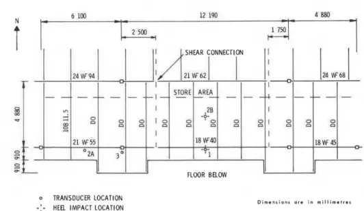
FLOOR BELOWo TRANSDUCER LOCATION
-
:
-
HEFL IMPACT LOCATIOND i m e n s i o n s a r e i n r n i l l i m e t r e s
FIG. 2. Area A (balcony) structural layout and location of transducers and heel impacts.
o TRANSDUCER LOCATION
-:-
HEEL IMPACT LOCATIOND i m e n s i o n s o r e i n m i l l i m e t r c s
FIG. 3. Area B structural layout and location of trans- ducers and heel impacts.
Part I of this paper describes the five floor areas, discusses the method used to obtain their dynamic prop- erties (namely, fundamental frequency, fundamental
damping ratio, and initial peak acceleration for the fun- damental frequency from heel impact), and compares the results with quiet occupancy criteria. Part I1
presents in some detail the method used to calculate the fundamental frequency and initial peak acceleration due to heel impact for the five floor areas.
Part I. Experimental results
Floor areas
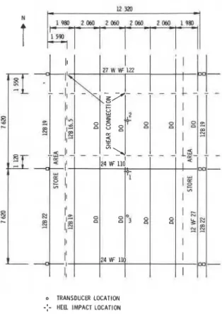
The three indoor floor areas are of the same com- posite construction. Each is a two-way, steel-beam floor system consisting of girders simply supportedon steel columns or girder cantilevers and floor beams simply supported on girders or beam cantilevers. The 34-4;-in. (89- 114 mm) composite concrete deck is covered by 2-in. (51 mm) terrazzo tile. A stucco- finished gypsum board ceiling is attached below. Struc- tural layouts are shown in Figs. 2-4. The two-way steel beam system has cantilevered sections in both directions in area C and in one direction, along the girders, in area A (balcony).
The upper level of the parking garage consists of simply supported, precast, prestressed, double-T beams 6 ft 9 in. (2060 mm) wide by 26 in. (660 mm) deep, supported on precast girders and columns. The double- Ts are shear connected at their flanges. Figure 5 shows the two parking areas where vibration measurements were conducted. The double Ts have clear spans of 38 ft (11.58 m) and 58 ft (17.68 m).
Test procedure and data analysis
Each floor area was excited by (a) several heel impacts (up on toes, down on heels) at each impact location (Figs. 2-5), and (b) footsteps of a man weigh-
PERNICA AND ALLEN 151
o TRANSDUCER LOCATION
-:-
HEEL IMPACT LOCATIONFIG. 4. Area C structural layout and location of trans-
ducers and heel impacts.
ing approximately 210 lb (95 kg) walking at a normil pace across the floor. For the two parking areas a com- pact car containing only the driver was driven across the floor at approximately 10 mph (16 km/h). At the time of the measurements the shopping centre was closed to the public.
Vertical acceleration was measured by means of accelerometers at several locations on each floor (Figs. 2-5). The output from each was appropriately ampli-
fied, low-pass filtered at 50 Hz, and then recorded on
a four-channel tape recorder.
Accelerometer records from heel impacts were anal- ysed on a Fourier spectrum analyser to determine the natural frequencies of each floor area. Each heel impact, walking, and driving record was then low-pass filtered at the fundamental floor frequency and dis- played on photosensitive paper using an oscillograph. Initial peak acceleration at each transducer location and the fundamental damping ratio of each floor area were determined from the visual heel impact records. In area
C (Fig. 4) it was difficult to obtain a good estimate of
the damping ratio for the fundamental mode with this procedure because of its small amplitude in the filtered signal. Table 1 shows the fundamental floor frequency,
o TRANSDUCER LOCATION 8 4 2 0 ~ )
-:-
HEEL IMPACT LOCATIOND l m a n ~ l o n $ mrm In m l l t 1 m m t r . 1 S E C T I O N A - A
FIG. 5. Parking garage areas, structural layout, and lo-
cation of transducers and heel impacts.
damping ratio, and initial peak accelerations' deter- mined from each set of heel impact tests.
For the walking and driving tests, maximum peak and average peak acceleration amplitudes at each accel- erometer location were determined from the filtered records. Only maximum peak acceleration amplitudes' are given in Table 1.
Comparison of test results with quiet criteria
Test results from heel impact are compared in Fig. 6 with annoyance criteria for quiet occupancies, using a damping ratio of 3%. Amplitudes from walking and driving tests are compared with criteria for continuous vibrations in Fig. 7. Figure 6 indicates that only area A and the 38-ft (1 1.58 m) span parking area would not be acceptable for quiet occupancies. Similarly, Fig. 7 indi- cates that walking vibrations in area A and the 38-ft
(1 1.58 m) span parking area and car vibrations in both
parking areas would be unacceptable for quiet occupancies. Interestingly, decreasing the clear span of the double Ts in the parking garage from 58 ft (17.68 m) to 38 ft (11.58 m), thereby substantially stiffening the floor system, actually reverses its accept- ability, using quiet occupancy criteria.
Discussion
Although area A and the 38-ft (1 1.58 m) span park- ing area would not be acceptable as floors for quiet
'Peak acceleration amplitudes given in Table 1 have been increased by 3 dB to compensate for the effect of low-pass filtering at the fundamental frequency.
TABLE 1. Results of floor vibration measurements Peak acceleration
at Fundamental Fundamental
Transducer Transducer location floor damping
setup Test frequency f ratio
Location (Figs.2-5) No. Type of test (1) (2) (3) (Hz) (%)
Area A (Fig. 2) A 1 Heel impact at (1) 53 4.8 4.3 5.6 2.5
2 Walkin9 past (1) (2) (3) 14 2.6 1.6
R 3 Hccl impact at (1) 45 14 3.7 5.6 2.5
4 I-lee1 impact at (2) 20 7.0 1.9 5.6 1.7
Area B (Fig. 3) A 5 Heel impact at (1) 7.0 8.7 9.2 4.0 3.3
6 Walkiny past (1) (2) (3) 2.6 3.0 3.2
B 7 Heel impact at (1) 7.7 3.1 1.5 4.0 3.1
8 Walking past (1) (2) (3) 2.8 2.0 1.4
Area C (Fig. 4) 9 Heel impact at (1) 8.9 1.2 6.3 5.2
-
510 Heel impact at (2) 1.0 14 1.4 5.2
11 Walking past (1) (2) (3) 2.9 4.0 2.6 12 Walking betwcen (1) and (3) 2.1 0.8 3.2
Parking garage A 13 Heel impact at ( I) 14 8.6 14 3.8 2.1
58 ft (17.68 m) 14 Walking past ( I) (2) (3) 3.6 4.0 3.6
span (Fig. 5) B 15 Heel impact ;it ( I ) 14 7.2 1 1 3.8 2.1
16 Driving past ( I ) (2) (3) 14 15 17
Parking garage A 17 Heel impact at (1) 28 16 18 8.4 2.2
38 ft (1 1.58 m) B 18 Heel impact at ( I ) 26 13 13 8.4 2.4
span (Fig. 5) 19 Walking past ( I ) (2) (3) 7.2 8.0 8.8
PERNICA AND ALLEN
-
CRITERIA FOR WALKING VIBRATIONS AS G I V m BY HEEL IMPACT TESTF R E Q U E N C Y . H z
FIG. 6 . Peak accelerations from heel impact compared with criteria for walking .vibrations for quiet occupancies; 1-area A (balcony); 2-area B; 3-area C; 4-parking ga- rage, 17.68 m span; 5-parking garage, 1 1 .58 m span.
occupancies (office, residential, etc .) , they were con- sidered acceptable as walking areas in a shopping cen- ter. This supports the hypothesis that criteria for quiet occupancies are conservative when applied to floors in active occupancies. Although quite limited, the infor- mation now reported suggests that quiet occupancy cri- teria can be increased by at least a factor of three for walking areas in shopping centres.
Part 11. Calculation of dynamic properties of floors
The assumptions and equations used to calculate the fundamental frequencies and initial peak accelerations due to heel impact of the five floor areas are discussed in the following sections to illustrate the fact that the dynamic properties of complicated one and two-way cantilever systems (areas A and C) can be determined as easily and reasonably as can those of simple beam con- struction (area B and parking areas).
Fundamental frequency
The fundamental frequencies of area B , the two park- ing areas, and the beam portion of area A were calcu- lated from [l] and are given in Table 2. These areas were assumed to behave essentially as one-way, simply-supported floor systems.
1 I I I
-CRITERIA FOR CONTINUOUS VIBRATION (10 TO 30 CYCLES)
-
-
0 7-
-
I . I-
4 2 . 0 3 I I 1 I F R E Q U E N C Y . H zFIG. 7 . Average peak accelerations from walking or driv- ing compared with criteria for continuous vibrations for quiet occupancies. Walking: I-area A (balcony); 2-area B; 3-area C; 4-parking garage 17.68 m span; 5-parking garage 1 1.58 m span. Driving: 6-parking garage, 17.68 m span; 7-parking garage, 11.58 m span.
= 156
I(;'
-
(Sl units)where E = modulus of elasticity in psi (MPa);
I = moment of inertia in in.4 (mm4); L = span in in. (mm); and w = dead load in lb/in. (N/mm).
The frequencies of the cantilevered systems of areas
A and C were also calculated using [I], as well as the properties of the suspended girders or floor beams. For area C the span L of the suspended members was taken as the full-span length. For area A the span L of the girder was taken as the average of the suspended span length and the full-span length. The reason for the dif- ference in the span L of areas A and C is as follows. For continuous or cantilever construction, adjacent spans vibrate in opposite directions at the fundamental fre- quency. The full span was used to calculate the funda- mental frequency for both the suspended beams and the girder in area C since, for either, the adjacent spans and the cantilevered and suspended member stiffnesses were approximately equal. For area A the spans were
154 CAN. J. CIV. ENG. VOL. 9. 1982
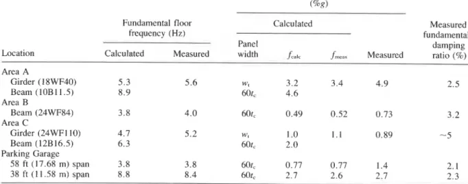
TABLE 2. Dynamic properties of floor areas
Initial peak acceleration from heel impact (%R)
Location
Fundamental floor Calculated Measured
frequency (Hz) fundamental
Panel damping
Calculated Measured width .fC.t f,,,,, Measured ratio (%)
Area A Girder (1 8WF40) 5.3 5.6 wt 3.2 3.4 4.9 2.5 Beam (10B11.5) 8.9 60t, 4.6 Area B Beam (24WF84) 3.8 4.0 60t, 0.49 0.52 0.73 3.2 Area C Girder (24WF 1 10) 4.7 5.2 WI 1 .O 1.1 0.89
-
5 Beam (12B16.5) 6.3 60t, 2.0 Parking Garage 58 ft (17.68 m) span 3.8 3.8 60t, 0.77 0.77 1.4 2.1 38 ft (1 1.58 m) span 8.8 8.4 60t, 2.7 2.6 2.7 2.3not equal, and the stiffnesses of the cantilevered mem- bers were greater than that of the suspended member; a reduced span for the suspended member was therefore more appropriate.
The moments of inertia for the three indoor floor areas were calculated assuming full composite action. The thickness of the concrete slab (terrazzo tile included) and its strength were assumed to be 5; in.
(140 mm) and 4 ksi (28 MPa), respectively. For the two
parking areas the moments of inertia of the precast, prestressed double Ts were calculated using the beam's full cross-sectional area. The concrete strength of the double Ts was assumed to be 7 ksi (48 MPa).
The modulus of elasticity for concrete was deter- mined from the following formula (Canadian Standards Association 1977):
[2] E = 57 0002/concrete strength in psi (psi)
= 5000t/concrete strength in MPa (MPa)
Calculated frequencies for the five floor areas are given in Table 2. Two frequencies were calculated for areas
A and C, one considering only the girder as the stiffness
element, the other only the floor beams. The calculated fundamental frequency of either floor area was assumed to be the smaller of the two values. Applying Dun- kerley's formula2 to obtain the fundamental frequency of either floor area from the girder and beam fre- quencies was considered to be an unnecessary refine- ment of this simple approach.
Initial peak acceleration
The initial peak acceleration, a. (in units of g), from
heel impact for the fundamental mode was calculated for the five floor areas (Allen and Rainer 1976):
-
- 2~rf1(0.9)
9.81M (S1 units)
where f is the fundamental frequency (Hz), I is an
impulse of 15 Ib-s, (67 N - s ) (Lenzen and Murray 1969), and M is an equivalent single-degree-of-freedom mass of the vibrating system. The mass M was calcu-
lated for the girder portions of areas A and C, using
where W is the tributary load supported by the member
(lb, kg). For the two parking areas, area B , and the
beam portions of areas A and C, M was calculated using
where t, is the effective thickness of the concrete slab (in., mm), and w, is the tributary width of floor support- ed by the member (in., mm). For suspended members,
W was determined using the span L employed in the
calculation of fundamental freiuencv. 1 , -
Equation [4a,b] assumes that for the calculation of
mass the impacted floor member and neighbouring floor area form a vibrating two-way panel, with length
L and width equal to the tributary width w, for girders
and 60t, for joists or beams resting on girders (Galambos 1973). The factor 0.405 converts the mass
PERNICA AND ALLEN 155 of this vibrating floor panel into the equivalent mass of
a simple oscillator.
Calculated and measured fundamental frequencies of each floor area were used in [3] to calculate the initial peak accelerations given in Table 2.
Comparison o f calculated and measured floor prop- erties
Calculated values of fundamental frequency differed by less than 10% from measured values for the five floor areas, indicating that the method used to calculate the fundamental frequencies of the girder-beam can- tilever systems in areas A and C was reasonable.
Calculated and measured values of a, did not agree as well as those of fundamental frequency. Measured val- ues of a, ranged from 0.9 to 1.8 times calculated values. Possible reasons for this sizeable variation include: a varying heel impact, although performed by the same person; the use of an average impulse of 15 Ib-s (67 N - s ) for the 210-lb (95 kg) heel impactor; the location of the transducers with respect to the fundamental mode shape of the floor area; the effects of continuity pro- duced by adjoining panels on the equivalent mass
M ;
and the contribution to the measured value of a, of other natural frequencies close to the fundamental.For the 58-ft (17.68 m) span parking area and area B calculated values of a, were substantially smaller than those measured. This large discrepancy was caused mainly by the presence in the filtered accelerometer
records of other natural frequencies whose con- tributions to a, were significant even after filtering.
Acknowledgements
The tests were conducted with the permission of the owners of the shopping centre. Their cooperation and that of all involved in the design and operation of the centre is greatly appreciated.
This paper is a contribution from the Division of Building Research, National Research Council of Canada, and is published with the approval of the Director of the Division.
ALLEN, D. E., and RAINER, J. H. 1976. Vibration criteria for long-span floors. Canadian Journal of Civil Engineering, 3, pp. 165-173.
ALLEN, D. E., RAINER, J . H., and PERNICA, G. 1979. Vibration criteria for long-span concrete floors. Pro- ceedings, American Concrete Institute Symposium on Vi- brations of Concrete Structures, New Orleans, pp. 67-78. CANADIAN STANDARDS ASSOCIATION. 1977. Code for the
design of concrete structures for buildings. National Stan- dard of Canada CAN3-A23.3-M77, Rexdale, Ont. GALAMBOS, T. V. 1973. Vibration of steel joist-concrete
slab floors. Technical Digest No. 5, Steel Joist Institute, Arlington, VA.
_
LENZEN, K. H., a n d ~ ~ R w , $ . M. 1969. Vibration of steel beam concrete slab floor systems. Report No. 29, Univer- sity of Kansas, Lawrence, KS.