HAL Id: hal-01021985
https://hal-enac.archives-ouvertes.fr/hal-01021985
Submitted on 4 Sep 2014
HAL is a multi-disciplinary open access
archive for the deposit and dissemination of
sci-entific research documents, whether they are
pub-lished or not. The documents may come from
teaching and research institutions in France or
abroad, or from public or private research centers.
L’archive ouverte pluridisciplinaire HAL, est
destinée au dépôt et à la diffusion de documents
scientifiques de niveau recherche, publiés ou non,
émanant des établissements d’enseignement et de
recherche français ou étrangers, des laboratoires
publics ou privés.
Improving modularity of interactive software with the
MDPC Architecture
Stéphane Conversy, Eric Barboni, David Navarre, Philippe Palanque
To cite this version:
Stéphane Conversy, Eric Barboni, David Navarre, Philippe Palanque. Improving modularity of
in-teractive software with the MDPC Architecture. EIS 2007, Engineering Inin-teractive Systems Joint
Working Conference, Mar 2007, Salamanca, Spain. pp 321-338, �10.1007/978-3-540-92698-6�.
�hal-01021985�
Improving modularity of interactive software with the
MDPC architecture
Stéphane Conversy1,2, Eric Barboni2, David Navarre2 & Philippe Palanque 2 1 ENAC – Ecole Nationale de l’Aviation Civile
7, avenue Edouard Belin, 31055 Toulouse, France. [email protected] 2 LIIHS – IRIT, Université Paul Sabatier 118 route de Narbonne, 31062 Toulouse Cedex 4, France {barboni, conversy, navarre, palanque}@irit.fr
http://liihs.irit.fr/{barboni, navarre, palanque}
Abstract. The “Model - Display view - Picking view - Controller” model is a
refinement of the MVC architecture. It introduces the “Picking View” component, which offloads the need from the controller to analytically compute the picked element. We describe how using the MPDC architecture leads to benefits in terms of modularity and descriptive ability when implementing interactive components. We report on the use of the MDPC architecture in a real application: we effectively measured gains in controller code, which is simpler and more focused.
Keywords: MVC, interactive software, modularity, Model Driven Architecture
1 Introduction
Modularity is an aspect of software engineering that helps improve quality and safety of software: once designed, implemented, and verified, modular components can be reused in multiple software so that such software can rely on their soundness. The advent of rich interaction on the web, and the advent of WIMP interaction in airplane cockpits [1][2] raise interest in interactive software architecture. The need to use, develop, and extend toolkits for interaction makes programmers eager to study this area. Similarly, a number of widgets have been formally described, so as to comply with important properties of interactive systems [14]. As a toolkit programmer point of view, reusing these components would ensure that his particular implementation complies with the same properties.
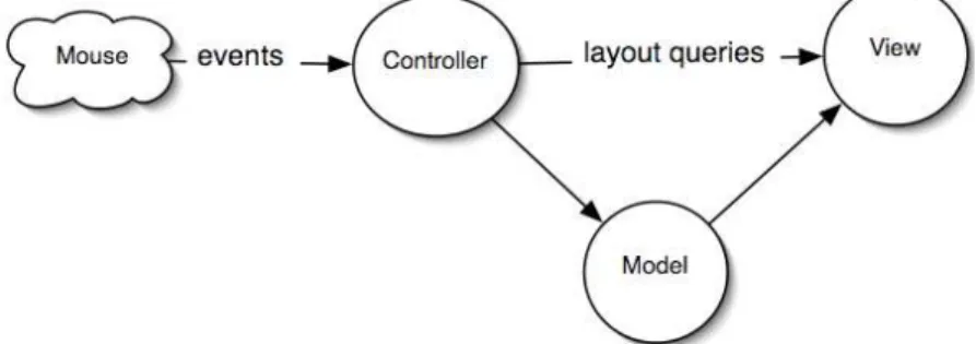
Separation of concerns is a design principle that can help to achieve modularity: the idea is to break a problem into separate sub-problems and design software components that would handle each sub-problem. The Model-View-Controller (MVC) architecture is a well-known attempt to improve modularity of software [18] through separation of concerns (cf Fig. 1). In MVC, the Model encapsulates the data to be interacted with, the View implements the graphical representation and is
updated when the Model changes, and the Controller translates actions from the user to operations on the Model. MVC has been successfully applied to high-level interactive components, though in this form it resembles more to the PAC architecture than its original description [6]. For example, frameworks to help develop interactive application, such as Microsoft MFC, organize the data structure in a document, and views on the document that are updated when the document changes. When applied to very low-level interactive components though, such as scrollbars, programmers encounter difficulties to clearly modularize the components so that the original goal of reusing components is reached: the View and the Controller components of the widget are so tightly coupled that it seems useless and a waste of time to separate them, as they cannot be reused for other interactive widgets1.
Fig. 1: MVC: The controller queries the view to know which part of the view has been clicked
in order to react accordingly.
We argue in this paper that by externalizing the picking concern from the Controller, we can actually modularize a set of interactive widgets so that the Controller can be reused across different classes of Views of the same model. We first present the causes of the problem mentioned above. We then introduce the Model – Display view – Picking view – Controller (MDPC) architecture, and show with examples how to use it. We then report our experience at refactoring a real application with the MDPC model.
2 The need to externalize Picking
At its lowest level, today's interactions usually involve a rasterized image (i.e. a digital/sampled/pixel-based image) and a pointer that the user controls to point at a given pixel. Rendering is the process of transforming a logical description or the
conceptual model of an interactive component to a graphical representation or a
perceptual model. Picking can be considered as the inverse process of rendering:
1
As stated by the designers of JAVA Swing: “We quickly discovered that this split didn't work well in practical terms because the view and controller parts of a component required a tight coupling (for example, it was very difficult to write a generic controller that didn't know specifics about the view). So we collapsed these two entities into a single UI (user-interface) object […]”.http://java.sun.com/products/jfc/tsc/articles/architecture/#roots
Picking is the process of determining/querying the graphical primitives that colored/filled a given pixel, and in turn the corresponding conceptual entity. Usually, interactive systems use the pixel underlying the cursor, in order to react when the user clicks on an interactive component. Picking is also used during passive movements, for example to determine when the cursor enters an interactive component so as to highlight it.
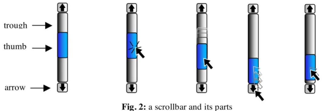
Fig. 2: a scrollbar and its parts
For the remaining of this section, we take the scrollbar as an example (Fig. 2). A scrollbar is an instrument that enables a user to specify the location of a range by direct manipulation. For example, the user can use a scrollbar to modify the position of the view of a document too large to be displayed at once. Conceptually, a scrollbar is composed of four parts: a thumb to control the position of a range of values, a
trough in which the user can drag the thumb, i.e. the position of the thumb is constrained inside the trough, and two arrows for decrementing/incrementing the position of the thumb by a fixed amount.
if( (event.y > y_up_widget) and (event.y <
y_bottom_widget) { // test if it is in the widget if (event.y < y_up_widget+harrow) {
// scroll down by one line ...
} else if (event.y<ythumb) {
// scroll down by one viewing area } else //...and so on
Fig. 3: An example of code using analytic picking
In the original form of MVC, the Controller usually handles picking by receiving low-level events such as mouse clicks or mouse moves. For example, if the user clicks in the image of a scrollbar for a text editor document, the Controller computes which part of the view has been clicked on, and calls a particular method of the Model with a computed parameter: if the part is one of the arrows, the Controller sets the Model's value by decreasing or increasing it by an amount equivalent to that of one line. If the part is the space between the thumb and the arrows, the amount is equivalent to that of one viewing area. In order to determine the part that has been clicked on, the Controller must know the layout of the widget parts, i.e the location of parts that are displayed on the screen [15]. For example, with a vertical scrollbar, if the upper ordinate of the widget is ywidget, the height of an arrow is harrow, and the upper
trough thumb
ordinate of the thumb is ythumb, a Controller can determine which part has been clicked
on by using the code in Fig. 3.
The code is embedded into the method that reacts to the click on the view. This prevents modularization of the controller: it is specially designed for one particular view, even if some of the values can be parameterized, such as the location of the whole widget. In particular, the relative layout of the different parts of the widget is often hard-coded, and is not a parameter of the widget.
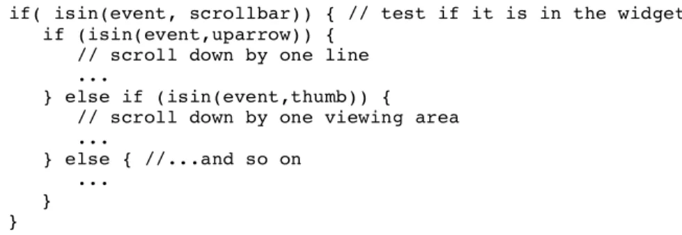
In fact, most interactive widgets are structured around parts that embody a spatial mode of interaction i.e. a same event in two different parts lead to two different behaviors of the widget. For example, clicking in an arrow triggers a different action than the one corresponding to clicking in the thumb. In a part, the action triggered by an event is the same regardless of the parameters of the event. Only the parameters of the action may depend on the dimensions of the event. What is important then to implement part-dependant code, is not the low level parameters of events such as the x and y coordinates, but the part on which the event took place. Thus, the Controller behavior must be dependant on parts below the cursor, and not the cursor’s x and y position, so that the code that describes it would resemble to code in Fig. 4.
if( isin(event, scrollbar)) { // test if it is in the widget if (isin(event,uparrow)) {
// scroll down by one line ...
} else if (isin(event,thumb)) { // scroll down by one viewing area ...
} else { //...and so on ...
} }
Fig. 4: An example of controller code independent of the exact position of parts
In this case, the "isin" function is a call to an external picking function. As such it is a mean to factor out the picking process from the Controller, and enables its reuse with other Views. However, implementing the controller with multiple if/then/else prevents extension and combination, as adding a part requires adding code to handle it. Instead, we propose to completely externalize the picking process, and make the Controller behavior dependant on Leave/Enter events, instead of Move events. Usually, programmers describe graphics by the mean of graphical shapes: instead of filling pixels by themselves, they use a higher level of description, for example a circle at a given position with a given radius. A graphical library in turn fills the pixels according to the description. A Leave event is triggered when the shape under the cursor changes between two consecutive Move events. A Leave event is immediately followed by an Enter event, as leaving a shape means that the cursor enters another shape (we consider the background as a shape with infinite size, which lies under every other shape). Leave and Enter events are synthesized events: they are computed from Move events, and a description of the layout and contours of the shapes in used. Thus, Leave/Enter events generation requires a data structure that keeps track of the layout of the shapes and their contours. This kind of data structure
is called a scene-graph. Usually, a scene-graph is used as an intermediate stage in the rendering process described above: the programmer describes the rendering of the conceptual model in terms of shapes, their geometrical and styling transformation, that are stored in a scene-graph. Since a scene-graph knows about the layout and contours of shapes, it is able to determine the shape that is under the cursor. Thus a scene-graph can handle input and implement a picking service, as well as synthesize
Leave/Enter events.
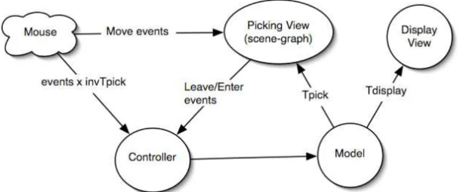
Fig. 5: The Model – Picking View – Display view Controller (MDPC) architecture
Display View and Picking View
We propose to split the View component into two components: the Display View, which is exactly the ancient MVC View, and the Picking View, which is an invisible rendering of the model that is specialized to facilitate interaction description. By splitting them, we deepen the separation of concerns aspect of the MVC model: while the display view handles the representation that has to be perceived by the user, the Picking View helps the determination of the part of the widget that is under the cursor. This separation also solves two problems of the design of interactive widgets, related to the differences between the structure of the graphics for interaction and the structure of the graphics for display: those due to graphic design concerns, and those due to transient, invisible interactive structure.
When developing widgets, a programmer can use graphical primitives that do not fit with interaction needs. For example a scrollbar can be seen as a thumb moving into a trough (Fig. 2). This can be described as two shapes, the thumb shape lying on top of the trough shape. If this structure were mapped to a scene graph, the Enter and Leave event would contain the identifier of the shapes, regardless of the position of the cursor relative to the thumb. Thus, the Controller would receive the same Move event, be it above the thumb, or below the thumb, and would not be able to discriminate the zone in which the cursor has actually entered (above or below the thumb), though this information is mandatory to implement control. This fact usually leads the programmer to implement analytic code, i.e. code that uses the x and y position of the thumb to eventually determine the zone. However, if the design of the view is done with three parts, the "decrease part", the thumb, and the "increase part", the only
information required to implement the interaction is the part identifier dimension of the Enter/Leave events. It is therefore necessary to decouple the display part of a widget from its picking part. Furthermore, interactive projects now involve graphic designers, whose creativity may be refrained by coding requirements. The separation between display and picking frees the graphic designer from the obligation to respect a graphical structure that does not map with the desired display: would the display view serves for both display and picking, the designer is required to use a three parts graphic, although two parts would have been enough. On the other hand, a designer can use as many graphical primitives she needs (like soft shadows, filters etc.), and in any configuration. In particular, she could have used sub-shapes like text of other images useful for the user to understand the display, but that are of no interest for interaction. As unnecessary graphical structures increases the complexity of formal checking of the controller code, reducing their number is important.
We saw above that the picking structure can be different from the display structure. But it can also change for the sake of interaction, while the display structure remains the same. In the scrollbar example, when one clicks on the thumb to move it along the trough, there are invisible zones in which spatial mode of interaction enters in action (Fig. 2, right). When the thumb "hits" the top or the bottom of the trough, the thumb does not move even if the user goes on with his movement, as the thumb is constrained in the borders of the widgets. However, when the user reverses his movement, there is a position from which the thumb starts moving again. This position is invisible, but can be computed as soon as the user clicks in the thumb: in the case of the vertical scrollbar, it is equal to the position of the widget plus the difference between the click and the top of the thumb. When the cursor is in this zone, the thumb moves as the cursor moves. When the cursor leaves this zone, and enters one of the two other zones, the thumb position is not updated anymore (and is set to 0 or 1). Usually, the interaction is described by using a "special mode" of the controller: as soon as the user clicks on the thumb, the controller "captures" the cursor so that moving it on top of unrelated display areas will not trigger associated actions. This behavior is traditionally implemented with analytic determination of distance from important points, such as the one described above. Instead, we propose to implement it using the same mechanism outlined above, namely with zones that are entered and left, with the difference that this time they are invisible and transient, as they are enabled only in certain states of the widgets. Hence, for one model, there can be one displayed view, whatever the interaction handled by the widget, and two different invisible, transient views to implement control, which leads to the split between Display Views and Picking Views.
3 Example 1: the scrollbar in depth
In this section we show how to use the MDPC model to describe the scrollbar. The model of the scrollbar is a range whose two boundaries lie in the range from 0 to 1 (Fig. 6). To specify values in an arbitrary range of values, not only 0 to 1, we can use a linear (i.e. ax+b) transform function when notifying observers. The Scrollbar widget enables a user to specify position of the range, i.e. she can slide the range so that both
boundaries are changed at the same time. The extent of the range (i.e. the difference between the boundaries) is specified by either the application, or is tied to another widget such as a text widget. The range-slider is a scrollbar widget, augmented with instruments that enable the user to specify the values of the boundaries. Hence, the Scrollbar and the Range-slider share the same model.
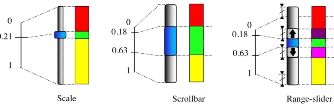
Fig. 6: From left to right, the Model, the Display View, and the Picking View of the Scale, the
Scrollbar, and the Range-slider. The model of the Scrollbar and the Range-slider is the same.
The display view is a drawing composed of several graphical shapes. In its simplest usable form, the drawing may resemble to Fig. 2: one background shape for the trough, and one shape for the thumb, lying over the background shape. The size of the trough is arbitrary chosen. The size of the thumb can be computed from the values of the model and the size of the trough, using a simple linear function. However, the thumb has a minimum size to allow the user to pick it regardless of the extent it is supposed to reflect. As explained above, the structure of the display view cannot be used to implement the control, as it is necessary to differentiate between the part of the trough that is above the thumb from the part that is below. Hence, the picking view is composed of three shapes, one for the thumb, and two for the visible parts of the trough. When the user manipulates the thumb, the position of the thumb shape is changed in the display view and in the picking view, while the size of the two sub-shapes of the trough are changed in the picking view. The controller of the scrollbar can then be described with events that contain the identifier of the shapes, as there is no need to analytically compute which part has been clicked on.
Invariance to geometrical transform and relative layout transform
The horizontal scrollbar is a 90° rotated vertical scrollbar. As such, it can be implemented by adding a 90° rotation in the display view and the picking view components. The interaction corresponding to a click in the arrows, and in the two parts of the trough, is exactly the same. However, in traditional MVC, the controller code of the vertical scrollbar has to be updated to handle the new positions of the parts. The controller as we defined it, does not need to be changed for a vertical scrollbar: it is invariant with respect to geometric transforms. This result is true for one type of interaction with the scrollbar, namely clicks in part that triggers action. 0 1 0.21 Range-slider Scrollbar Scale 0 1 0.18 0.63 0 1 0.18 0.63
With the 90° rotation example, the vertical movement corresponding to the manipulation of the trough is not compatible with the orientation of the scrollbar. To overcome this problem, we use the inverse transform that enables the generation of the view, by transforming the events so that their coordinates are relative to the view, and not absolute (or relative to the screen). Using the inverse transforms, the controller remains the same.
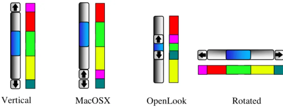
Fig. 7: The Display View, and the Picking View of varieties of Scrollbar.
Moreover, the controller is invariant with respect to the relative layout of parts of the scrollbar. As shown on SEQ, the arrows can be move at one extremity of the trough (to mimic a variety of MacOSX scrollbar), or even at the ends of the thumb (to mimic OpenLook scrollbar). The same MDPC controller as the vertical scrollbar can control these kinds of scrollbar, whereas with MVC each variant requires a different controller.
Multiple picking views for transient behavior
When sliding the trough though, the user can go outside the widget and still hold control of the scrollbar. This has been handled in traditional architecture with a special mode of interaction, namely by “capturing” the cursor so that any other underlying system such as MVC is bypassed. With our model, moving outside the widget will trigger a Leave event, and eventually stops the controller. This behavior is due to the fact that dragging the thumb is actually a completely different interaction than clicking in scrollbar parts. In fact, the picking model is different from the one described above. The sliding interaction is dependent on three zones: one in which moving the cursor moves the thumb (or more precisely, set the boundaries of the scrollbar model, which is reflected by the view as a displacement of the thumb), and two in which movement has no effect on the model (and hence on the view of the thumb) because the thumb hit one of the edges of the trough. This can be implemented as another picking view (see SEQ, left). When clicking on the thumb, the “waiting-for-click” picking view of SEQ is replaced by the “sliding” picking view. When the cursor moves inside the central part, the thumb follows its position. When the cursor enters the upper part, the value of the Model is set to 0, and does not move until it reenters the central area again. As long as the user holds the button
OpenLook
pressed, the controller receives Leave, Enter and Move events and reacts accordingly. When the user releases the cursor, the “waiting-for-click” picking view comes back.
Fig. 8: To the left, the state-machine describing the behavior of the scrollbar. To the right, a
simplified version with the transitions with associated actions only.
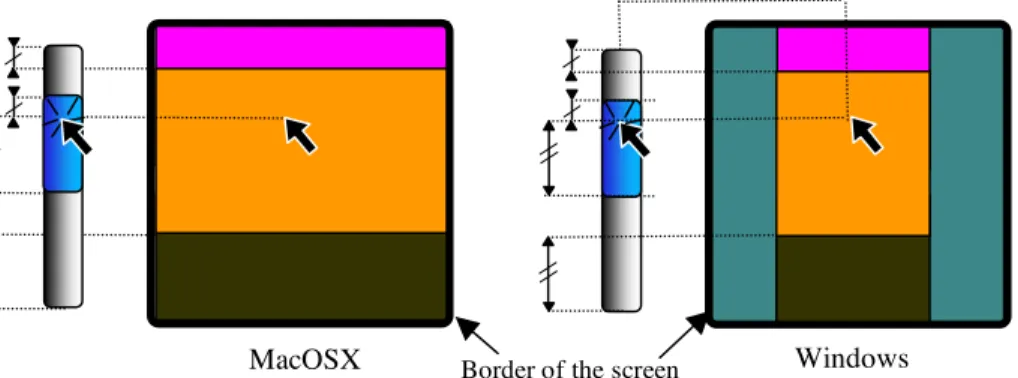
Fig. 9: when clicking on the thumb, a new Picking View is used. The thick rounded rectangle
reflects the border of the screen.
To assess the universality of this model, we can describe a variation of this interaction. While sliding the thumb, the user can move the cursor at a particular distance from the scrollbar. With a MacOSX scrollbar, this distance is infinite, and can be described with rectangular zones that extent horizontally up to the border of the screen. With a Windows scrollbar, the distance is finite, and when crossed, the thumb goes back to the position it has at the beginning of the interaction (i.e. when the user clicks on the thumb), enabling the user to cancel the interaction. This can be described by shrinking the three zones of the picking view (SEQ, right), so that the background appears at their sides: when the cursor enters the background zone, the Controller resets the thumb position back to its previous value.
Windows MacOSX Border of the screen
4 Example 2: the bar chart and the pie chart
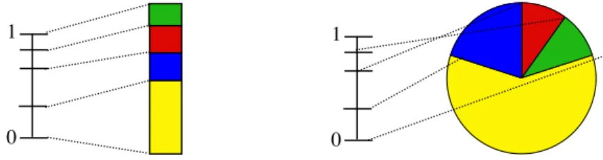
Fig. 10: the Model of the partition and two Display Views: a Pie Chart, and a Bar Chart.
A partition model can be considered as a list of floats that range from 0 to 1. Each pair of floats specifies an interval. It can be represented with a bar chart, in which each part’s height is proportional to its interval. It can also be represented with a pie chart, in which the extent angle of each part is proportional to its interval. Charts are often used as visualization only. However, a user can specify the values by clicking and dragging the borders between each part. Fig. 11 shows a picking view that enables this interaction. Thick borders reflect the interactive parts. They might be invisible in the display view, but are necessary to ease interaction. When clicking on a border, the second picking view enters in action, and precludes the user to move a value below or above neighbor values. It seems difficult to use the same controller for both Bar and Pie picking views since they are so different. However, they are topologically equivalent. We can use the inverse of the transform that generates the view: the Bar view involves a transformation from Cartesian coordinates, while the Chart view involves a transformation from polar coordinates.
Fig. 11: Above: the “wait-for-click” Picking View and “sliding” Picking View of the Bar
Chart. Below: the “wait-for-click” Picking View and sliding Picking View of a Pie Chart. Both “sliding” picking view prevent the user to move a value below or above neighbor values.
0 1 0 1 0 1
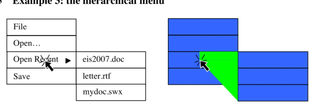
5 Example 3: the hierarchical menu
Fig. 12: the Display View and Picking View of a deployed hierarchical menu.
When clicking on an entry of a hierarchical menu that has sub-entries, a pull-down menu shows up. On MacOSX, the controller allows the user to “fly over” entries of the first menu and reach entries of the submenu that are displayed at the bottom and left of the current location of the cursor. If the cursor goes downward vertically, it enters another entry, and the sub-menu hides itself. If the user does not initiate the interaction after a few milliseconds, the “fly over” mode is stopped. As shown in Fig. 12, it can be implemented with a transient triangular-like shape in the Picking View. Apart from the fact that the MDPC model eases the comprehension of the behavior, it leads again to less code in the controller, as no analytical computation is necessary to implement control. Moreover, it simplifies the architecture of the code, since no special mode of interaction in which the cursor is captured is necessary. It also shows that the picking structure can be very different from the display structure: it needs a transient state in which a shape helps implement interaction, but that is hidden to the developer. Finally, the set of necessary shapes for picking are less important than the set necessary for display (for each entry in the hierarchical menu: a sub-shape for the background, the text, the triangle icon). When using the same scene-graph for both display and picking, special code that prevents action for Leave/Enter events involving sub-shapes is needed. Separating the scene-graphs removes this obligation, and leads to smaller, more focused, code.
6 Return of experience with a real application
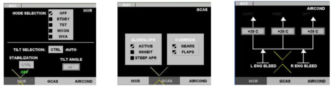
We updated the architecture of a real application that uses the ARINC 661 set of widgets [2]. The purpose of ARINC 661 specification [1] is to define interfaces to a Cockpit Display System used in interactive cockpits. MPIA is an airborne application that uses the ARINC 661 specification, and that aims at handling several flight parameters. It is made up of 3 pages (called WXR, GCAS and AIRCOND) between which crewmember are allowed to navigate using 3 buttons (as shown on Fig. 13). Interaction with MPIA relies on button-like widgets exclusively. Though we did not use the button as an example in previous sections, our observation that controller code is polluted by picking code holds true: with the previous architecture, picking is done
File Open…
Open Recent eis2007.doc letter.rtf mydoc.swx Save
by traversing the tree of widgets and by checking for each widget whether it is picked We want to show with this example that externalizing the picking process leads to more simpler, more focused code.
Fig. 13: the three pages of MPIA
Though we described control with state machines so far, for this application we used the ICO formalism [17], which is based on Petri-Nets. The next section describes how rendering is done using declarative specifications, and how the renderer implements picking services for the handling of low-level user input events.
Rendering
In the previous version, rendering was implemented with Java code, using the Java2D API. Instead, we now rely on an SVG description. SVG is an xml-based vector graphics format: it describes graphical primitives in terms of analytical shapes and transformations. As such, SVG is a scene-graph. To render SVG, we use the Batik renderer. Transforms from models to graphics are done with XSLT. XSLT is an xml-based format that describes how to transform an xml description (the source) to another xml description (the target). An XSLT description is called a “stylesheet”. XLST is traditionnaly used in batch mode to transform a set of xml files, but XSLT can also be used in memory so that performances are compatible with interaction. We used the Apache Xalan library to handle XSLT transforms.
In our case, the source is a DOM description of the components the application: the “ARINC tree”. It is built at startup time, together with the instantiation of the ICOs components. Before running the application, the system compiles two stylesheets to two XSLT transformers: one for the display view, and one for the picking view (Fig. 14). This compilation can be triggered at any time, to update a stylesheet while designing and implementing it. While running the application, each time the state of an ARINC tree variable changes, the transformer transforms the ARINC tree to two DOM SVG trees, which in turn are passed to the SVG renderer (Fig. 16). The display view is then displayed in a window, while the picking view is rendered in an offscreen window.
Each time the cursor moves on the display view, the picking manager “picks” the topmost graphical item of the picking view at the position of the cursor, as if the cursor was moving over the picking view instead of the display view. Then, the picking manager sends an event to the Petri nets with the cursor position and the ID of
the graphical item under the cursor as parameters. The Petri nets specification then uses the ID to retrieve the instance of the models over which the cursor is.
arinc xml description: <arinc>
<button x="10" y="10" width="200" height="50" text=”submit” enable=”1”/>
</arinc>
xslt stylesheet: <xsl:stylesheet>
<xsl:template name="button">
<rect x="{@x}" y="{-(@y+@height)}" width="{@width}" height="{@height}" rx="150" fill="url(#gradientPanelBackground)”/>
<text x="{@x}" y=”{-@y}">submit</text> </xsl:stylesheet>
generated svg:
<rect x="100" y="-60" width="200" height="50" rx="150" fill="url(#gradientPanelBackground)”/>
<text x="100" y="-50">submit</text>
Fig. 14. Examples of an ARINC tree, an XSLT transformer, and the resulting SVG Picking
Advantages of the architecture
Our goal with this application is to show that it is possible to externalize picking from the controller. The resulting refactoring first shows that the architecture is implementable, and that it enabled us to reduce the complexity of the controller code by a significant amount (about 25% less), without removing functionality. While applying it to the entire modeling of the MPIA application and the user interface server compliant with ARINC 661 specification this produced a significant reduction of model size as shown in Fig. 15. This difference is more salient with widgets in charge of the assembly of widgets as the ones shown Fig. 15. For other terminal widgets (like command buttons, text boxes), the reduction of models size is still present but more limited.
Model size without MDPC
Model size with MDPC Widget
Places Transitions Places Transitions
RadioBox 49 29 28 21
TabbedPanelGroup 62 22 44 16
TabbedPanel 72 49 22 7
Panel 65 46 16 5
Fig. 16: The run-time architecture
This architecture clearly distinguishes the conceptual model from the perceptual model, and gathers all the graphics and transforms description into one external entity. It has clear advantages over the previous architecture. First, it increases readability of the graphical code. Second, changing the look of an application is as simple as changing the XSLT file. Fig. 17 shows two renderings that can be alternatively presented without making any change in the models describing the widgets. Most commercial drawing and painting software can produce SVG graphics compatible with our system, allowing graphic artists to be involved earlier in the design process of interactive applications [5]. Finally, rendering is considered as a transformation process that uses functional programming without side-effect, which increases robustness [9]. It is also interesting to note that the advantages of the architecture are demonstrated both at the level of programming code and at the level of model description. <xsl:stylesheet> <xsl:template name=”button”> <xsl:template name=”button”…> <xsl:template…> <xsl:template> <xsl:…> <scollbar …> <arinc> <button x=…> <tabbedpanel> <panel> <panel> <rect …> <svg> <g> <rect> <rect> <rect x=…> <xsl:stylesheet> <xsl:template name=”button”> <xsl:template name=”button”…> <xsl:template…> <xsl:template> <xsl:…>
ICO description ARINC DOM SVG DOM
XSLT Transformer
SVG Renderer and picking manager
Events (x, y, id)
display
picking
display picking
Drawbacks of the new architecture
The performance of dedicated Java2D code is much better than the one exploiting SVG, XSLT, and Batik. The low performance of the new architecture comes from the fact that the transformation process involves the entire conceptual model each time it is triggered, leading to a whole new SVG DOM, even if a single variable of the ARINC DOM has changed. This problem is related to the current status of transforming tools, which are unable to do incremental transformations. An incremental transformer is able to only update the changing parts of the target tree, which increases performances (up to 500 times) [16][22]. Another solution is to use “active transformations”, i.e. transformation systems and specifications designed to implement incremental transformations [2].
Fig. 17: The same User Application window with two different stylesheets
7 Related work
Fabrik is a direct manipulation - based user interface builder that enables a designer to specify transforms between widget with a visual flow language [10]. Events flow in the same flow graph that describes the geometrical transforms, so that they are automatically transformed to a position relative to the graphically transformed widget. In [7], Dragicevic and Fekete introduce the MVzmC architecture. Like MDPC, the widget is divided into zones that embody a spatial mode of interaction. The “view controller” plays the role of our transform mechanism, and works similarly to Fabrik transforms. However, the Vzm component is still in charge of determining which zone has been hit, hence it is not invariant to changes of relative layout of parts. Similarly, in the Event-driven MVC [20], the code that handles picking is buried into the view, and hence precludes any simple change of layout. MDPC clearly factors out this task from the Controller and the View, which leads to more reusable code. Finally, both the MVzmC and Event-driven MVC use a single view, and cannot be used to implement transient picking structure.
Using a declarative description of an interface is not new (see [21] for a review). However, in much of these systems, the description is only a way to get the interface outside the code of the application: a run-time environment displays widgets by interpreting the description. Furthermore, the description is only about the layout of
predefined WIMP widgets at the finer level of details. Such systems are primarily targeted at toolkit users (i.e. interactive application designers) that do not need to implement new or slightly different interaction techniques. In our case, the architecture describes all models, from the level of the application down to the inner mechanics of a widget. For example, we can describe the control and the rendering of a range slider using the same architecture that we use to describe the application, while it’s not possible with other systems.
The idea of transforming a conceptual model to a perceptual model comes from the Indigo project [4], a novel client-server architecture for highly interactive systems. While X11 splits rendering and interaction between the server and the client, Indigo makes the server in charge of the rendering and the interaction. To reflect changes of the logic of the client into the rendering, Indigo uses a transformation process similar to the one described in this paper. Indigo widgets are part of the server, and the rendering is not done using a transformation process. In our architecture, we apply the transformation model to the inner mechanics of the widgets. Transforms are also used in [13], but it is done once at the instantiation of widgets from a layout description, while transforms are used continuously in our architecture.
8 Discussion
This work attempts to tackle the question often asked when disserting about the MVC model: what is a controller exactly? As inventors of MVC apply separation of concerns to interaction code, we can apply separation of concerns down to the Controller itself: in MVC, the controller handles picking, the backward translation of dimension of events to arguments for operations on the model, and the management of the interactive state of interactive components (as opposed to graphical state). In MDPC, the combination of the scene-graph (the picking view) and Leave/Enter events synthesis handles picking. The picking code is hence offloaded from the Controller code, which makes the controller simpler. In order to pass computed values from events to arguments for operations on the model, the old Controller has to transform dimensions of the events in the widget referential: hence, it is dependent on the View, as it must queried its parameters (such as the orientation) to compute the inverse transform. This backward translation from the dimensions of the events to arguments for operation on the model can be handled by the inverse transform mechanism in the MDPC model. We have shown how to do it functionally with rotated scrollbar and pie charts. If this translation is more complex, it can be dealt with with a similar mechanism to MVzmC’s one, i.e. a View Controller. Hence, in the MDPC architecture, what we call a controller is the piece of code that manages the interactive state of a component, i.e. the state-machine or the Petri Net that describes it. The interactive state is different from the graphical state. The graphic state is just a direct translation from the model to a graphical representation. For example, if a scrollbar is disabled because the interface does not allow the user to interact with it, there should be a Boolean in the model that should reflect it, and that would be used to draw a disabled toolbar (for example in gray). The management of interactive state is the core functionality of the Controller: it defines the behavior, or the inter-actions
between the user and the model, i.e. the intertwined sequences of actions from the user, and actions from the system that change the set of future actions at user’s disposal. With such a definition, Controllers presented in this paper seem simple. However, when dealing with multiple inputs, the description is complex, and may require Petri Nets with dozens of places and transitions. With the MPIA application, the code associated to transition is limited to change of values in the model, without any other computations. Hence the Controller is the Petri net, and almost nothing else, except the rules that change values in the model. In other words, it seems to us that it is impossible to remove other aspects of the Controller, as we reduced it to its crux.
Another goal of this project was to foster the use of an MDA approach to the design of interactive application. We designed the models of our widgets in order to make them as independent as possible from controllers and views, which led to the merge of the scrollbar model and the range slider model into a single range model. The choice of setting the bounds of the values inside the models to a range of [0,1] makes the model even more reusable, since the addition of a linear function makes it general enough to describe previous use of scrollbars. Our approach is an attempt to maximize the late binding aspect of our components: MDPC makes use of late binding of range bounds, of positions, and of relative position of parts.
9 Conclusion
In this paper, we have presented a new architecture for interactive systems implementation. We split the View component of MVC in a Picking View and Display View components. The picking task, traditionally handled by controllers of interactive widgets, is offloaded to a picking manager, which turns Move events to Leave/Enter events by using the picking view. Widgets following this architecture gain invariance from relative layout of components and invariance from geometrical transforms. The Controller code shrinks and is more focused to its functional core. The architecture can also be used to implement invisible, transient interactive structure. One of the goal of this project is to have a complete MDA driven widget set. The MDPC architecture is a first step towards this objective, as it enables the definition of interactive systems based on a MDA approach. The controller is specified using a formalism such as Petri Nets, the display and picking view are specified with a transformation model based on declarative specifications. In order to fully accomplish our goal, we need better and more efficient transform tools. In particular, we plan to design incremental, and bidirectional transform engine, in order to ease the definition of transforms. Another result is more conceptual: thinking of control as leaving/entering/moving over/clicking on possibly invisible parts helps design and describe it, as shown in the hierarchical menu example.
Acknowledgments. This work is partly funded by DPAC (Direction des Programmes de l'Aviation Civile) étude “validation cockpit interactif” and by EU via the Network of Excellence ResIST (www.resist-noe.org).
References
1. ARINC 661 specification: Cockpit Display System Interfaces To User Systems, Prepared by Airlines Electronic Engineering Commitee, Published by Aeronautical Radio, 2002.
2. Barboni, E., Conversy, S., Navarre, D. & Palanque, P. Model-Based Engineering of Widgets, User Applications and Servers Compliant with ARINC 661 Specification. Proc of DSVIS 2006, Lecture Notes in Computer Science, Springer Verlag
3. Beaudoux O., 2005. XML Active Transformation (eXAcT): Transforming Documents within Interactive Systems. Proc of the 2005 ACM Symposium on Document Engineering (DocEng 2005), ACM Press, pages 146-148.
4. Blanch R., Beaudouin-Lafon, M., Conversy, S., Jestin, Y., Baudel, T. and Zhao, Y. P. INDIGO : une architecture pour la conception d'applications graphiques interactives distribuées. In Proceedings of IHM 2005, pages 139-146, Toulouse - France, Sept. 2005
5. Chatty, S., Sire, S., Vinot, J., Lecoanet, P., Lemort, A., and Mertz, C. 2004. Revisiting visual interface programming: creating GUI tools for designers and programmers. In Proceedings of UIST '04. ACM Press, New York, NY, 267-276
6. Coutaz, J. PAC, an Object Oriented Model for Dialog Design, in Proc. of Interact'87 (North Holland, 1987), 431-436.
7. Dragicevic P. and Fekete J-D. Étude d'une boîte à outils multi-dispositifs. Proc. of the 11th French speaking conf. on Human-Computer Interaction (IHM'99), pages 33-36, 1999
8. Extensible Markup Language (XML) 1.0 (Third Edition) W3C Recommendation http://www.w3.org/TR/REC-xml/
9. Hudak, P. 1989. Conception, evolution, and application of functional programming languages. ACM Comput. Surv. 21, 3 (Sep. 1989), 359-411.
10. Ingalls, D., Wallace, S., Chow, Y., Ludolph, F., and Doyle, K. 1988. Fabrik: a visual programming environment. In Proc of OOPSLA (San Diego, California, United States, September 25 - 30, 1988). ACM Press, New York, NY, 176-190.
11. Jacob, R. J. 1996. A Visual Language for Non-WIMP User Interfaces. In Proc. of Symposium on Visual Languages (1996). VL. IEEE Computer Society, Washington, 231.
12. Krasner, G. E. and Pope, S. T. 1988. A cookbook for using the model-view controller user interface paradigm in Smalltalk-80. J. Object Oriented Program. 1, 3 (Aug. 1988), 26-49.
13. Limbourg, Q., Vanderdonckt, J., Michotte, B., Bouillon, L., Víctor López Jaquero, UsiXML: a Language Supporting Multi-Path Development of User Interfaces, Proc. of EHCI-DSVIS'2004 (Hamburg, July 11-13, 2004), Lecture Notes in Computer Science, Vol. 3425, Springer-Verlag, Berlin, 2005, pp. 200-220.
14. Navarre David; Palanque Philippe; Bastide Rémi, and Sy Ousmane. Structuring interactive systems specifications for executability and prototypability. 7th Eurographics workshop on Design, Specification and Verification of Interactive Systems, DSV-IS'2000; LNCS n° 1946.
15. Olsen, D. R. 1998. Developing User Interfaces, Morgan Kaufmann.
16. Onizuka, M., Chan, F. Y., Michigami, R., and Honishi, T. 2005. Incremental maintenance for materialized XPath/XSLT views. In Proc. of WWW '05. ACM Press, 671-681.
17. Palanque P., R. Bastide. Petri nets with objects for specification, design and validation of user-driven interfaces. In proc. of IFIP Interact'90. Cambridge 27-31 August 1990 (UK).
18. Samet H., 1990, Applications of Spatial Data Structures: Computer Graphics, Image Processing, GIS, Addison-Wesley, Reading, MA, 1990.
19. Scalable Vector Graphics (SVG) 1.1 Specification http://www.w3.org/TR/SVG11/
20. Shan, Y. 1989. An event-driven model-view-controller framework for Smalltalk. In Conference Proceedings on Object-Oriented Programming Systems, Languages and Applications. OOPSLA '89. ACM Press, New York, NY, 347-352.
21. Souchon, N., Vanderdonckt, J., A Review of XML-Compliant User Interface Description Languages, Proc. of 10th Int. Conf. on Design, Specification, and Verification of Interactive Systems DSV-IS'2003 (Madeira, 4-6 June 2003, LNCS, Vol. 2844, Springer-Verlag, Berlin, 2003, pp. 377-391. 22. Villard, L. and Layaïda, N. 2002. An incremental XSLT transformation processor for XML document
manipulation. In Proc. of WWW '02. ACM Press, pp 474-485.