HAL Id: hal-01877590
https://hal.archives-ouvertes.fr/hal-01877590
Submitted on 20 Sep 2018
HAL is a multi-disciplinary open access
archive for the deposit and dissemination of
sci-entific research documents, whether they are
pub-lished or not. The documents may come from
teaching and research institutions in France or
abroad, or from public or private research centers.
L’archive ouverte pluridisciplinaire HAL, est
destinée au dépôt et à la diffusion de documents
scientifiques de niveau recherche, publiés ou non,
émanant des établissements d’enseignement et de
recherche français ou étrangers, des laboratoires
publics ou privés.
Impact of swirl and bluff-body on the transfer function
of premixed flames
M. Gatti, R. Gaudron, Clement Mirat, Laurent Zimmer, Thierry Schuller
To cite this version:
M. Gatti, R. Gaudron, Clement Mirat, Laurent Zimmer, Thierry Schuller. Impact of swirl and
bluff-body on the transfer function of premixed flames. Proceedings of the Combustion Institute, Elsevier,
2018, �10.1016/j.proci.2018.06.148�. �hal-01877590�
Impact of swirl and bluff-body on the transfer function of premixed flames
M. Gattia,∗, R. Gaudrona, C. Mirata, L. Zimmera, T. Schullera,b
aLaboratoire EM2C, CNRS, CentraleSup´elec, Universit´e Paris-Saclay, 3, rue Joliot Curie, 91192 Gif-sur-Yvette cedex, France bInstitut de M´ecanique des Fluides de Toulouse, IMFT, Universit´e de Toulouse, CNRS, Toulouse, France
Abstract
The frequency response of three lean methane/air flames submitted to flowrate perturbations is analyzed for flames featuring the same equivalence ratio and thermal power, but a different stabilization mechanism. The first flame is stabilized by a central bluff body without swirl, the second one by the same bluff body with the addition of swirl and the last one only by swirl without central insert. In the two last cases, the swirl level is roughly the same. These three flames feature different shapes and heat release distributions, but their Flame Transfer Function (FTF) feature about the same phase lag at low frequencies. The gain of the FTF also shows the same behavior for the flame stabilized by the central insert without swirl and the one fully aerodynamically stabilized by swirl. Shedding of vortical structures from the injector nozzle that grow and rollup the flame tip controls the FTF of these flames. The flame stabilized by the swirler-plus-bluff-body system features a peculiar response with a large drop of the FTF gain around a frequency at which large swirl number oscillations are observed. Velocity measurements in cold flow conditions reveal a strong reduction of the size of the vortical structures shed from the injector lip at this frequency. The flame stabilized aerodynamically only by swirl and the one stabilized by the bluff body without swirl don’t exhibit any FTF gain drop at low frequencies. In the former case, large swirl number oscillations are still identified, but large vortical structures shed from the nozzle also persist at the same forcing frequency in the cold flow response. These different flame responses are found to be related to the dynamics of the internal recirculation region, which response strongly differs depending upon the mechanism adopted to stabilize the flame.
Keywords: Flame dynamics, Transfer function, Swirl number fluctuations
∗
Corresponding author:
Email address: [email protected] (M. Gatti)
1. Introduction
The frequency response of premixed swirling flames submitted to flow rate modulations is a topic of high sci-entific and technical interest due to the problems raised by combustion instabilities in gas turbines [1–3]. This response is often characterized by a Flame Transfer Function (FTF) or more recently by a Flame Describ-ing Function (FDF) when the level of flow disturbances is considered [4].
Changing the shape of the FTF/FDF by modifying the injector design is a way to augment the stability mar-gins of a combustor. However, there is still no system-atic way to make these changes, because the dynamics of swirling flames is not fully understood [4, 5]. Im-proved combustor stability is thus gained by a costly trial and error iterative process and there is a need for better knowledge of the fundamental mechanisms con-trolling the shape of the FTF of swirling flames.
The FTF of premixed swirling flames can be deter-mined analytically in simplified configurations [6–8] or by numerical flow simulations in more complex geome-tries [9–11]. Most often this response is determined experimentally by using well proven optical techniques [12–15] even in engine like conditions [16].
Since shear layers are highly responsive to acous-tic forcing, the FTF of premixed flames stabilized by a bluff body is mainly controlled by the shedding of large coherent structures, which are then convected by the mean flow and roll-up the flame. This flame roll-up process around a coherent vortical structure constitutes the main contribution controlling the FTF phase lag of premixed laminar [17] and turbulent non-swirling jet flames [18]. It also constitutes one of the fundamental process controlling the dynamics of premixed swirling flames [19–21].
It has been demonstrated that the response of the swirling vane needs to be taken into account in the dy-namics of swirling flames [20, 22, 23]. Vortical trans-verse perturbations triggered by the axial flow distur-bances at the swirler outlet lead to oscillations of the swirl level at the burner outlet. This in turn leads to oscillations of the flame angle at the anchoring point lo-cation [19]. This swirl oscillation mechanism and its impact on the FTF have been identified in several setups in which the flame is stabilized by a central bluff body [20, 22, 23]. The same dynamics is observed when the acoustic pulsation is introduced from the upstream or downstream side of the swirler [24].
In high power systems, the flame is most often fully aerodynamically stabilized without the help of any solid central insert. Giuliani et al. [25] also report large swirl
number oscillations in the response of an aeronautical injector powered by kerosene when it is submitted to flow rate modulations. They however provide no FTF data. Biagioli et al. [10] analyzed the FTF of aerody-namically swirl-stabilized flames and found that the po-sition of the Internal Recirculation Zone (IRZ) and the flame leading edge respond to the acoustic forcing by a large axial motion, but the tangential flow component is not considered in their analysis and one cannot conclude about the role of swirl oscillations.
There is yet no detailed investigation on the impact of swirl number oscillations on the FTF of swirling flames aerodynamically stabilized away from all solid compo-nents. This response is analyzed here for flames stabi-lized either only by a bluff body, only by swirl or by both swirl and bluff body. The premixed flames inves-tigated feature the same equivalence ratio and the same thermal power.
The experimental setup and diagnostics are presented in section 2, followed by a description in section 3 of their flame structure in the absence of forcing. Their frequency response is analyzed in section 4 for the dif-ferent injectors tested. The flow and flame dynamics at selected frequencies are investigated in section 5 to in-fer the swirl number fluctuations and the mechanisms controlling the response of these flames. Conclusions are finally drawn in section 6.
2. Experimental setup
The experimental setup is sketched in Fig. 1. The burner is powered by a methane/air mixture. Experi-ments are conducted at a fixed equivalence ratio φ = 0.82 and bulk velocity Ub = 5.44 m/s (T = 20oC and
p = 1 atm) in the D = 22 mm diameter section be-fore the swirler unit. These conditions correspond to a constant thermal power P = 5.44 kW assuming total combustion.
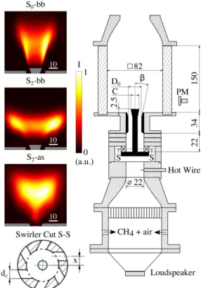
Two different radial swirlers can be fixed in the in-jection unit. They both feature six radial inin-jection chan-nels of dc= 6 mm diameter. The design of swirlers S0
and S2only differ by the distance x indicated in Fig. 1.
In the first device, designated as S0, the channels are
aligned with the radial direction (x= 0 mm). In the sec-ond one, designated as S2, the channels are shifted from
the radial direction by x= 6 mm, to impart a strong ro-tation to the flow.
The flow leaves the swirler through an injector that can take two different designs. It is a straight tube of diameter D = 22 mm with a central rod of diameter d = 6 mm, topped by a cone of diameter C = 14 mm and 10 mm length, to stabilize flames S0-bb and S2-bb
shown in Fig. 1. The cone protrudes 2.5 mm inside the combustion chamber from the injector backplane. The distance between the swirler back-plane and the cham-ber back-plane is L = 56 mm. For flame S2-as at the
bottom in Fig. 1, the central rod is removed and the flame is fully stabilized aerodynamically. The central injection tube is in this case slightly modified and com-prises a tube with diameter D= 22 mm over a first sec-tion of length L1 = 22 mm, followed by a nozzle of
length L2= 34 mm, which is terminated by a diverging
cup with an angle β= 15◦. The nozzle throat diameter is in this case D0= 12 mm in Fig. 1.
The combustion chamber has an 82 mm square cross-section and a length of 150 mm, and is equipped with four quartz windows. At the base of the burner, a loud-speaker (Monacor SP-6/108PRO, 100 Watts RMS) is mounted to pulsate the flow. The velocity is measured with a hot wire anemometer probe (Dantec Dynamics -Probe 55P16 with a mini-CTA 54T30) below the swirler unit where the velocity has a top hat profile. A pho-tomultiplier (Hamamatsu, H5784-04), equipped with a narrowband filter (Asahi Spectra, ZBPA310) centered around 310 nm and with a 10 nm bandwidth, is used to record the OH* chemiluminescence signal.
A 2D-2C Particle Image Velocimetry (PIV) system is also used to analyze the flow structure at the injector outlet under cold flow operation. Small oil droplets of diameter 1-3 µm are, in this case, seeded in the flow. The PIV system consists of 2×400 mJ Nd:YAG laser doubled at 532 nm operated at 10 Hz and a 2048×2048 px2 CCD camera (Dantec Dynamics, FlowSense EO
4M). Two different optical setups are used for longi-tudinal and transverse measurements, with a time de-lay between the two laser pulses∆t =10 µs and a pixel pitch of 27.9 px/mm in the first case and∆t =25 µs with a pixel pitch of 40.1 px/mm in the second one. Eight hundred images are taken to obtain converged mean and rms values of the velocity field, which is deduced from the cross-correlation of the PIV images by a three passes window deformation technique (from 64×64 px2 to 16×16 px2 interrogation areas), with an uncertainty of 0.1 px on the calculated displacement.
An intensified CCD camera (Princeton Instruments, PI-MAX 4, 1024×1024 px2), mounted with an UV
ob-jective (Nikkor 105 mm f/4.5) and equipped with the same filter as the photomultiplier, is also used to ana-lyze the flame structure under steady and forced condi-tions. Phased averaged images of the OH* signals and the PIV fields are synchronized by the signal driving the loudspeaker.
Fig. 1. Experimental setup. S0-bb : Non-swirling flame
an-chored by a bluff-body, D0 = 22 mm, C = 14 mm. S2− bb :
Flame stabilized by swirl S = 0.8 and the bluff-body, D0 =
22 mm, C = 14 mm. S2-as : Swirling flame S = 0.75
sta-bilized aerodynamically, D0 = 12 mm, β = 15◦. The main
dimensions are indicated in millimeters.
3. Steady injection conditions
The PIV data gathered in the axial plane and a trans-verse plane 2 mm above the top cone of the central bluff-body (flames S0-bb, S2-bb) and 2 mm above the injector
outlet (flame S2-as) are first used to determine the swirl
number S [4] at the injector outlet : S=0.20 for S0-bb,
S=0.80 for S2-bb and S=0.75 for S2-as, with a relative
precision ±3%.
The swirl level for flame S0-bb slightly differs from
zero due to small imperfections in the swirler manufac-turing. Several PIV measurements were made to check this feature that was found to be reproducible, with the same velocity profile, from tests to tests by mounting and demounting the swirler and the rod. Nonetheless, the swirl number S = 0.2 remains in this case small and the configuration S0-bb will be referred in the following
as a non-swirling flame.
Effects of the swirl number S on the shape taken by the flames are shown in Fig. 1. The flame S0-bb is
an-0 1 2 0 50 100 150 200 250 300 0 2
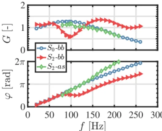
Fig. 2. Gain G and phase lag ϕ of the FTF for the three con-figurations investigated at the forcing level u0/u = 0.30 RMS.
chored on the bluff body at the top in Fig. 1 with a rel-atively narrow reaction layer spreading over a long dis-tance in the wake of the central bluff-body. The flame S2-bb produced by the same injector but with a higher
swirl S = 0.8 is more compact in Fig. 1. When the cen-tral rod is removed, Fig. 1 shows that the lifted flame S2-as has about the same axial extent as flame S0-bb
but with an emission intensity peaking in the central re-gion.
4. Flame transfer functions
The FTF of the three preceding flames is determined from the velocity signal measured by the hot wire anemometer and the OH* chemiluminescence intensity Imeasured by the photomultiplier gathering light from the whole combustion region. This signal is assumed to be a good tracer of the heat release rate. Flames are excited by the loudspeaker in the frequency range 20-260 Hz with a constant modulation level u0/u=0.3,
where u and u0denote the mean and root-mean-square
(RMS) values of the velocity signal measured by the hot wire. The FTF is deduced from the cross- and power-spectral densities of the hot wire and photomultiplier signals evaluated at the forcing frequency f :
F ( f )= I
0/I
u0/u =G( f ) exp(iϕ( f )) (1)
Results are plotted in Fig. 2. The FTF gain curve of flame S0-bb shows a typical low-pass filter behavior
with a large gain overshoot at low frequencies, a well known feature of the acoustic response of laminar and turbulent premixed non-swirling V-flames anchored on a central bluff body [17, 18, 26].
The FTF of the flame S2-bb obtained with the same
injector design, but a swirl level S = 0.80, differs from
flame S0-bb by several aspects in Fig. 2. The FTF
gain of S2-bb shows a succession of a peak, a
val-ley at f0 = 96 Hz and another peak over a short
fre-quency range, over which the non-swirling flame S0-bb
response remains maximum. These features are now well understood and documented in a series of theoreti-cal, numerical and experimental studies [7, 22, 23, 27]. They result from interferences between axial and az-imuthal velocity fluctuations that are produced at the swirler outlet. It has been demonstrated that the fre-quency f0 at which the FTF gain of a swirling flame
reaches its minimum is obtained for the largest swirl number oscillation, i.e. a situation where azimuthal and axial velocity fluctuations are out of phase at the burner outlet [23].
The frequency f0can be roughly estimated by
consid-ering the phase-lag ϕu0
θ−u0z between azimuthal and axial
velocity fluctuations at the injector outlet [27, 28]:
ϕu0 θ−u0z= 2π f0δ 1 uc −1 c ! (2)
where ucis the convection velocity of azimuthal
distur-bances and c uc is the speed of sound. The
con-dition leading to the highest swirl number oscillation amplitude, i.e. a minimum FTF gain, corresponds to ϕu0
θ−u0z = π. The distance δ in Eq. (2) is between the top
of the swirler injection channels, where azimuthal dis-turbances are generated, and the combustor backplane. It is thus slightly smaller than the distance L = 56 mm between the swirler and the combustor backplanes. It was shown in [11, 23, 28] that the velocity uc is close
to the maximum velocity reached by the flow in the in-jection channel. This velocity remains unknown in the present study, but a rough estimate is made here by tak-ing it equal to the highest axial velocity uc= 9 m/s
mea-sured at the injector outlet with PIV (not shown). The same choice was made in [23]. One finds f0 = 90 Hz
for uc = 9 m/s and δ = 50 mm. This estimate is close
to f0 = 96 Hz determined experimentally in Fig. 2 for
flame S2-bb. The largest uncertainty comes from the
value of the convection velocity uc, which depends on
the flow structure between the swirler injection channel outlets and the burner outlet.
The FTF of the swirling flame S2-as obtained without
central insert does not feature any significant FTF gain drop in Fig. 2 even though the swirl level S = 0.75 is close to the value S = 0.80 for flame S2-bb anchored on
the bluff body. One may again roughly estimate the fre-quency f0associated to the largest swirl number
oscilla-tions. Considering the reduction of the injection tube di-ameter, one now takes uc,1= 5.44 m/s over δ1= 16 mm
and uc,2 = 18.2 m/s over δ2 = 34 mm deduced from
mass balance (see Fig. 1) and finds f0 = 104 Hz.
This frequency is well inside the range investigated but, nonetheless, there is no drop of the FTF gain in Fig. 2 for flame S2-as.
Other interesting features, which seem to have not been reported previously, are observed for the FTF phase lag in Fig. 2. The phase lag curve of the non-swirling S0-bb and highly swirled S2-bb flames
an-chored on the central bluff body are the same at low frequencies f < f0. This is not an obvious feature since
the time lag τ appearing in the FTF phase lag ϕ= 2π f τ is generally proportional to the flame length Lf and to
the inverse of the bulk flow velocity 1/Ub. In Fig. 1,
ob-tained for steady injection conditions, the flame length Lf and flame aspect ratio largely differ between S0-bb
and S2-bb while the bulk flow velocity remains the
same. At higher frequencies f > f0, the FTF phase lag
of the non-swirling flame S0-bb keeps increasing with
an almost constant slope in the full frequency range in-vestigated. An inflection point and a rapid change of the phase lag characterize the response of the highly swirled flame S2-bb at frequencies close to f ∼ f0. At
higher forcing frequencies, the data for the FTF phase lag of flame S2-bb are found to be parallel to the FTF
phase lag plot of the non-swirling flame S0-bb offset by
a constant value of ϕ0' −1.3 rad. The FTF phase lag of
the aerodynamically stabilized swirled flame S2-as
reg-ularly increases with a different slope than flame S0-bb
and does not exhibit any inflection point.
5. Flame dynamics
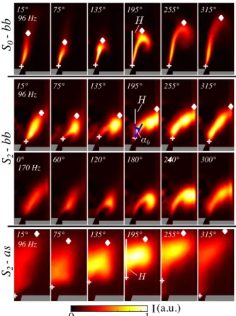
Phase averaged images of the OH* chemilumines-cence conditioned by the harmonic excitation are ex-amined in Fig. 3 to elucidate some of the previous ob-servations. The forcing level u0/u = 0.30 RMS is the
same as in Fig. 2 showing the FTF results. The in-tensified CCD camera is synchronized with the signal driving the loudspeaker at the bottom of the burner. Im-ages are taken for each configuration at the same phases separated by a constant interval of 30o. The phase
an-gles are indicated in Fig. 3 with respect to the hot-wire signal below the radial swirler and a phase shift arises between flames forced at 96 Hz and 170 Hz. An Abel deconvolution reveals the trace of the flame luminos-ity in an axial plane crossing the burner axis for flames S0-bb and S2-bb. This post-processing was not possible
for flame S2-as due to the too high intensity values close
to the symmetry axis (see Fig. 1). The same color scale is used for all images to better highlight both the flame motion and changes of the flame luminosity during the forcing cycle.
I
0
1
(a.u.)
αb 96 Hz 96 Hz 170 Hz 96 HzS
2- as
S
2- bb
S
0- bb
15° 75° 135° 195° 255° 315° 0° 60° 120° 180° 240° 300° 15° 75° 135° 195° 255° 315° 15° 75° 135° 195° 255° 315° Fig. 3. OH∗intensity phase averaged images at a forcing level u0/u = 0.30 RMS. + : flame root position. 3 : flame tip
position.
The first sequence in Fig. 3 highlights the large mo-tion undergone by the non-swirling flame S0-bb at the
forcing frequency f = 96 Hz when the FTF gain is max-imum in Fig. 2. Large roll-up of the flame tip is seen at 195◦ and 255◦. The flame is stretched in the vertical
direction during the forcing cycle with relatively minor changes of the OH* luminosity.
The second and third sequences in Fig. 3 show the responses of flame S2-bb, at the FTF gain minimum at
f0= 96 Hz and at the FTF gain maximum at f = 170 Hz
in Fig. 2. The motion undergone by the flame does not differ significantly at these two forcing frequencies, but it is mainly changes of the flame luminosity that ex-plain the large differences observed for the FTF gain at f0 = 96 Hz and f = 170 Hz in Fig. 2. At f0 = 96 Hz,
there is a relatively weak flame roll-up motion accom-panied by weak changes of the flame luminosity over the forcing cycle in Fig. 3. At f = 170 Hz, the flame roll-up process is a bit further pronounced, but the OH* luminosity undergoes large changes during the forcing cycle explaining the high value taken by the FTF gain at
0 2 3 4 -3 -1.5 0 1.5 0 2 3 4 0 2 3 4 -4.5 0 4.5
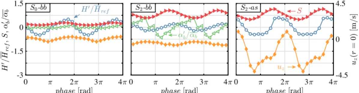
Fig. 4. Evolutions of the swirl number S and axial velocity uz(r= 0) at the burner outlet with respect to the phase of the hot-wire
signal. The relative flame height H0/H
re f and flame base angle α0b/αb oscillations are also plotted. Two oscillation cycles are
represented for better readability.
this frequency in Fig. 2.
The last sequence in Fig. 3 shows the dynamics of the aerodynamically stabilized flame S2-as at f = 96 Hz
corresponding to its peak FTF gain value in Fig. 2. The flame is rolled-up by vortex interaction (75◦-195◦)
and is stretched in the vertical direction, but also un-dergoes large changes of its luminosity as flame S2-bb
at f = 170 Hz. The position of the leading edge of flame S2-as also exhibits a large vertical oscillation
dur-ing the forcdur-ing cycle, as highlighted by the white crosses in this sequence, while flames S0-bb and S2-bb remain
anchored on the bluff body in Fig. 3.
Further analysis is made at the forcing frequency f0 = 96 Hz by determining the average flame position
for each image sequences. This profile is obtained by finding the maximum row-wise intensity of the pixel lu-minosity, weighted by the distance from the burner axis as expressed by: R I(r, x)2πrdr. A threshold of 25% is selected to delineate the lower (cross symbol) and upper (diamond symbol) flame boundaries. For flame S2-as in
the last sequence in Fig. 3, the flame contour is used in place of the average flame position for the analysis.
This post-processing is used to deduce the flame height H corresponding to the vertical distance between the upper (diamond sign) and lower (plus sign) flame boundaries i.e. the length of the vertical white segment shown in Fig. 3 at the phase 195o. This process proves to
be efficient and robust even when the flame is strongly modulated by vortex interaction. The flame angle αb
with respect to the vertical direction is also determined at the flame leading edge position as shown in the sec-ond sequence in Fig. 3 at 195o. Evolutions of H and α
b
are plotted in Fig. 4 over two periods for the three flames S0-bb, S2-bb and S2-as excited at f = 96 Hz. The same
reference height Hre f = 25 mm is used to normalize
the results. The three flames exhibit a modulation of their height H during the forcing cycle, but the oscilla-tion amplitude H0is a bit lower for S
2-bb compared to
S0-bb and S2-as. The swirling flame S2-bb stabilized
by the bluff body also features a large oscillation of the flame angle αb at its base at f0 = 96 Hz. These flame
angle oscillations are not observed for the non-swirling flame S0-bb and could not be determined for the fully
aerodynamically stabilized flame S2-as.
Figure 4 also shows the evolution of the swirl num-ber S at the injector outlet, determined, for each se-lected phase in the cycle, by PIV measurements con-ducted in cold flow conditions, with a relative precision of ±5%. One clearly identifies a large modulation of the swirl level at f = 96 Hz for the swirling flames S2-bb
with and S2-as without bluff body, while at the same
frequency there are no swirl oscillations for the flame S0-bb. This analysis confirms that both flames, S2-bb
and S2-as, undergo large swirl number oscillations at
f = 96 Hz, but their FTF largely differ even though they share about the same swirl level S ∼ 0.8.
Finally, the axial velocity signal uzon the symmetry
axis r = 0 is examined in Fig. 4. This signal measured 2 mm above the top cone is barely altered by the flow modulation at f0 = 96 Hz for flames S0-bb and S2-bb
anchored in the wake of the central bluff body. This con-trasts with the large oscillation in Fig. 4 observed for the same signal measured 2 mm above the injector outlet for the swirling flame S2-as without bluff body. This large
modulation is responsible for the displacement of the leading edge position of the aerodynamically stabilized flame S2-as in the bottom image sequences in Fig. 3.
Further analysis is now carried out under cold flow conditions by examining the dynamics of coherent vor-tical disturbances synchronized by the acoustic pulsa-tion. Results are presented in Fig. 5. To identify vortical structures, the Q criterion [29] is selected:
Q= 1 2(|Ω|
2− |S|2) (3)
where S andΩ are the symmetric and anti-symmetric 6
0 1 2 3×10 6
s
-2S
0-bb
S
2-bb
S
2-as
96 Hz 96 Hz 96 Hz 170 HzFig. 5. Q criterion contour obtained from PIV measurements in cold flow conditions, for a forcing level u0/u = 0.30 RMS. Isolines
of axial velocity are superimposed. Black contour: uz= 0 m/s. Gray contour: uz= −2.5 m/s. The position where the axial velocity
uzfor the analysis of Fig. 4 is measured, is shown as a green cross at the phase 15o.
components of the velocity gradient respectively. Iso-contours of Q are inferred from PIV measurements in the axial plane. Only positive values of Q are re-tained. Negative values, indicating regions where shear is present but no swirling motion, are forced to a zero value.
In the first, third and last sequences in Fig. 5, cor-responding to FTF gain maxima in Fig. 2, large vor-tical structures generated at the rim of the injector are produced by the acoustic forcing and convected down-stream in the chamber. In the second sequence in Fig. 5 corresponding to the FTF gain minimum in Fig. 2 for flame S2-bb at f0 = 96 Hz, vortical structures are much
weaker as emphasized by the much lower values taken by the Q criterion. As a consequence, the flame re-sponse remains low at this forcing frequency.
Isolines of axial velocity are also shown in Fig. 5, to highlight the different dynamics of the internal re-circulation zone depending upon the flame stabilization mechanism. Flame S0-bb feature a small recirculation
region in the wake of the bluff-body. Flame S2-bb
fea-ture a larger IRZ, undergoing a flapping motion during the forcing cycle, which is more evident at f0= 96 Hz.
When the flame is stabilized without bluff-body, S2-as,
the IRZ is much thinner and oscillates vertically in and
out of the injector.
These observations are confronted with current inter-pretations of the response of swirling flames associated with the combined effects of swirl number oscillations and flame vortex roll-up. Palies et al. [19] explained that at the FTF gain minimum, large swirl number os-cillations modulate the strength of the IRZ. This oscil-lation weakens the formation of eddies and also leads to flame base angle oscillations. When the flame an-gle fluctuates, vortex growth is rapidly hindered by the flame flapping motion and the flame response is low. When the flame angle oscillation weakens, the response is high because vortices can fully develop before inter-acting with the flame. Interaction of vortex shedding and flame angle fluctuations has been further analyzed in [20]. These authors argue that as the flame moves closer to the shear layer, the vorticity of the flow is dissi-pated due to its interaction with the flame and the flame response is low. In contrast, when the mean flame po-sition is stationary, the vorticity of the flow is not dissi-pated before interacting with the flame, which leads to a large flame response.
The observations made in this work are for some as-pects consistent with these conclusions, but also reveal new mechanisms. Figure 4 confirms that swirl
num-ber and flame base angle oscillations are large for flame S2-bb stabilized by a bluff body at f0 = 96 Hz where the
FTF gain is at a minimum. It is however found that the formation of large vortical structures are damped even without combustion. This phenomenon is here not re-lated to the flapping motion of the flame, but is found to be related to the geometry of the injector. At the same excitation frequency, large vortical structures are shed from the injector without bluff-body, while large swirl level oscillations are also observed. In this case, the re-sponse of flame S2-as remains high. This flame also
ex-hibits a large vertical oscillation of its leading edge and a peak value of the FTF gain at f = 96 Hz. This analysis reveals that the mechanisms controlling the frequency response of swirled flames largely differ when they are stabilized by a bluff body or when they are stabilized aerodynamically, the main differences being related to the dynamics of the IRZ.
6. Conclusion
Transfer functions of flames stabilized with ent injector designs have been investigated for differ-ent swirl levels, with and without a cdiffer-entral insert in the injector. Depending on the stabilization mechanism, flame vortex roll-up, oscillations of the flame base an-gle induced by swirl level oscillations and vertical os-cillations of the flame leading edge, are found to be the competing mechanisms controlling the flame response. When the FTF gain is at a maximum, the three flames investigated are strongly modulated by the interaction with large vortical structures convected in the external shear layer of the flow, regardless of changes of the swirl level and stabilization mechanisms. In contrast, the for-mation of large vortical structures is hindered, even in cold flow conditions, at the frequency corresponding to a minimum in the FTF gain curve, which is observed in the present study only for the swirling flame stabilized by a bluff body. At this frequency, large swirl number oscillations lead to a modulation of the flame base angle and weak vortex formation. At the same frequency, but for the aerodynamically stabilized flame without central insert, swirl number oscillations of the same order of magnitude are observed, but the gain of the FTF remains high. In this case, large vortical structures are shed and the flame leading edge oscillates vertically. The origin of the low response of swirling flames at specific fre-quencies is found to not only be related to large oscilla-tions of the swirl level, but also to the flame stabilization mechanism and more specifically to the dynamics of the internal recirculation region.
Acknowledgements
This project has received funding from the Euro-pean Union’s Horizon 2020 research and innovation programme under the Marie Sklodowska-Curie grant agreement No 643134. This work is supported by Agence Nationale de la Recherche, NOISEDYN project (ANR-14-CE35-0025-01).
References
[1] T. C. Lieuwen, V. Yang, Combustion Instabilities: Basic Con-cepts, 2005.
[2] Y. Huang, V. Yang, Prog. Energy Combust. Sci. 35 (2009) 293– 364.
[3] T. Poinsot, Proc. Combust. Inst. 36 (2017) 1–28.
[4] S. Candel, D. Durox, T. Schuller, J.-F. Bourgouin, J. P. Moeck, Annu. Rev. Fluid Mech. 46 (2014) 147–173.
[5] S. K. Thumuluru, T. Lieuwen, Proc. Combust. Inst. 32 (2009) 2893–2900.
[6] C. Hirsch, D. Fanaca, P. Reddy, W. Polifke, T. Sattelmayer, in: Proc. ASME Turbo Expo 2005, GT2005-68195.
[7] P. Palies, T. Schuller, D. Durox, S. Candel, Proc. Combust. Inst. 33 (2011) 2967–2974.
[8] V. Acharya, Shreekrishna, D.-H. Shin, T. Lieuwen, Combust. Flame 159 (2012) 1139–1150.
[9] L. Tay Wo Chong, R. Kaess, T. Komarek, S. Foller, W. Polifke, in: Proc. ASME Turbo Expo 2010, GT2010-22769.
[10] F. Biagioli, B. Paikert, F. Genin, N. Noiray, S. Bernero, K. Syed, Flow, Turbul. Combust. 90 (2013) 343–372.
[11] V. Acharya, T. Lieuwen, Phys. Fluids 27 (2015) 105106. [12] C. Kulsheimer, H. Buchner, Combust. Flame 131 (2002) 70–84. [13] D. Kim, J. G. Lee, B. D. Quay, D. A. Santavicca, K. Kim, J.
Eng. Gas Turbines Power 132 (2010) 757–765.
[14] P. Palies, D. Durox, T. Schuller, S. Candel, Combust. Sci. Tech-nol. 183 (2011) 704–717.
[15] B. ´Cosi´c, S. Terhaar, J. P. Moeck, C. O. Paschereit, Combust. Flame 162 (2015) 1046–1062.
[16] B. Schuermans, F. Guethe, D. Pennell, D. Guyot, C. O. Paschereit, J. Eng. Gas Turbines Power 132 (2010) 111503. [17] D. Durox, T. Schuller, S. Candel, Proc. Combust. Inst. 30 (2005)
1717–1724.
[18] R. Balachandran, B. O. Ayoola, C. F. Kaminski, A. P. Dowling, E. Mastorakos, Combust. Flame 143 (2005) 37–55.
[19] P. Palies, T. Schuller, D. Durox, L. Y. Gicquel, S. Candel, Phys. Fluids 23 (2011) 037101.
[20] N. A. Bunce, B. D. Quay, D. A. Santavicca, J. Eng. Gas Turbines Power 136 (2013) 021503.
[21] K. Oberleithner, S. Schimek, C. O. Paschereit, Combust. Flame 162 (2015) 86–99.
[22] T. Komarek, W. Polifke, J. Eng. Gas Turbines Power 132 (2010). [23] P. Palies, D. Durox, T. Schuller, S. Candel, Combust. Flame 157
(2010) 1698–1717.
[24] R. Gaudron, M. Gatti, C. Mirat, T. Schuller, in: Proc. ASME Turbo Expo 2018, GT2018-76381.
[25] F. Giuliani, P. Gajan, O. Diers, M. Ledoux, Proc. Combust. Inst. 29 (2002) 91–98.
[26] T. Schuller, D. Durox, S. Candel, Combust. Flame 134 (2003) 21–34.
[27] K. T. Kim, D. A. Santavicca, Combust. Flame 160 (2013) 1441– 1457.
[28] P. Palies, D. Durox, T. Schuller, S. Candel, J. Fluid Mech. 672 (2011) 545–569.
[29] J. Jeong, F. Hussain, J. Fluid Mech. 285 (1995) 69–94.