DISTORTION IN PULSE-DURATION MODULATION
E. R. KRETZMER
TECHNICAL REPORT NO. I I
RESEARCH LABORATORY OF ELECTRONICS
MASSACHUSETTS INSTITUTE OF TECHNOLOGYDistortion in Pulse-Duration Modulation*
ERNEST R. KRETZMERt, STUDENT, I.R.E.Summary-Pulse-duration modulation inherently gives rise to a certain amount of audio distortion. The analysis presented in this paper relates the distortion to system parameters. The method of analysis is exact, and therefore correct for any degree of modulation. It does not, however, lend itself to periodic sampling. The results are applied to three specific cases.
I. INTRODUCTION
SPECTRUM analysis of duration-modulated pulses may be of interest in systems where
pulse-duration modulation is used directly, or where
* Decimal classification: R148.6. Original manuscript received by the Institute, September 30, 1946; revised manuscript received, March 20, 1947. The research reported in this document was made possible through support extended the Massachusetts Institute of Technology, Research Laboratory of Electronics, jointly by the Army :Signal Corps, the Navy Department (Office of Naval Research), and the Army Air Forces (Air Materiel Command), under the Signal .Corps Contract No. W-36-039 sc-32037.
tResearch Laboratory of Electronics, Massachusetts Institute of 'Technology, Cambridge 39, Mass.
pulse-position modulation is converted to pulse-duration modulation for decoding.t
The problem investigated here may be classed under the general heading of the analysis of waves derived by sampling a signal wave at discrete intervals. This gen-eral problem exists in one form or another in all pulse communication systems, where it is a well-known prin-ciple that the sampling rate should be at least twice the highest frequency to be transmitted for faithful
repro-duction.2
Several papers including analyses of pulses with dura-tion or posidura-tion moduladura-tion, as well as comments on
these, have recently been published. Most of these, '"Pulse position modulation technic," Electronic Ind., vol. 4, pp. 82-87, 180-190; December, 1945.
2 W. R. Bennett, Time division multiplex systems," Bell Sys.
Kretzmer: Distortion in Pulse-Duration Modulation
however, do not take into account the precise law of modulation, which determines the time instant at which the signal is sampled and used to produce a time shift." The analysis presented here applies to that law of modu-lation which is believed to be most practical.
II. TERMINOLOGY AND NOTATION
The time function to be analyzed is a sequence of rec-tangular pulses, for convenience chosen to be of unit amplitude.
The notation use is as follows:
p =angular pulse-repetition frequency q =angular frequency of modulating signal do=average or unmodulated pulse duration
d =variable pulse duration k =modulation index=d -dm
dmax+dmtn n=harmonic index number of p m =harmonic index number of q
Anp+mq =amplitude of a sinusoidal component of angular frequency np+mq
Un p+,q=relative intermodulation distortion due to
Anp+mq; Unp q= Anmq
Aq
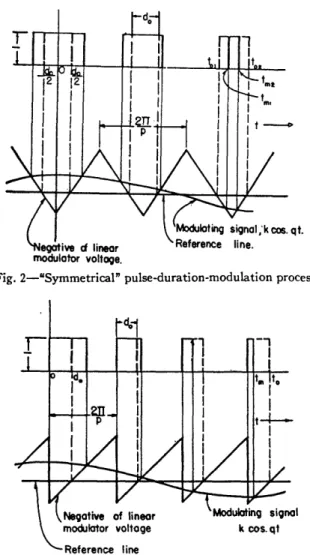
Two types of pulse-duration modulation are consid-ered: (a) symmetrical," and (b) asymmetrical. The former has application primarily to pulse-duration modulation as such3,7; the latter has direct application to some present-day pulse-position-modulation systems. In asymmetrical pulse-duration modulation only one of the two pulse edges is time-modulated, while the other one is fixed. In symmetrical" pulse-duration modula-tion both edges are modulated. The word symmetrical" is enclosed in quotation marks because, although both edges move, they do not, in general, move by equal and opposite amounts.
III. ANALYSIS OF ACTUAL MODULATION PROCESS
In position or duration modulation the pulses or pulse edges are shifted by amounts proportional to the instan-taneous signal values sampled at certain instants at ap-proximately the time of the pulse or pulse edge. Before any analysis is made, one must first determine exactly what these certain instants are. In a few instances in the
3 G. L. Fredendall, K. Schlesinger, and A. C. Schroeder, Trans-mission of television sound on the picture carrier," PROC. I.R.E., vol. 34, pp. 49-61; February, 1946.
' F. F. Roberts and J. C. Simmonds, Multichannel communica-tions systems. Preliminary investigation based upon modulated
pulses," Wireless Eng., vol. 22, pp. 538-549: November, 1945. 6 R. B. Shepherd, Letter to the Editor," Wireless Eng., vol. 23, pp. 114-115: April, 1946.
6F. F. Roberts and J. C. Simmonds, Letter to the Editor,"
Wire-less Eng., vol. 23, p. 204; July, 1946.
7 W. A. Beatty, Proposals for television and broadcasting sys-tems," Jour. Instn.Radio Eng., vol. 5, pp. 54-78; March-April, 1945.
literatures-5 these instants were assumed to be fixed and equally spaced along the time axis. In other cases, no specification was made.
Most time modulators are based on the principle that the sum of the signal voltage and a linearly rising or fall-ing voltage crosses a given reference voltage at an in-stant of time which is a function of the signal, a pulse edge being produced at that instant.4,8- 0 t is shown in Fig. 1 that the instant of crossing is a function of the
_e,, -a(to-t)
-k co qt
a(t.-t)
Fig. 1-Illustration of time-position-modulation process.
signal value at the instant of crossing only. The lin-early changing voltage is here represented by e =a(to
-t), the signal by e = k cos qt, and the reference line by
e = 0. The time t at which the total voltage crosses this
line is given implicitly by [e.+e,] t
,,,
=0:(la) k cos qt,,, + a(to - t,) = 0
k
t = to + - cos qt,. a
Stated in words, the time shift (t,-to) of a given pulse edge is proportional to the instantaneous modulating signal at the instant t at which the pulse edge actually occurs. It should be noted that the condition (la) can also be written in the form
k cos (qt,) = - a(to - t,). (ic) This shows that the pulse edge, i.e., the instant t,,, oc-curs when the signal voltage and the negative of the lear voltage (indicated by the dot-dash line in Fig. 1) in-tersect. This idea is useful for graphical construction of modulated pulses (see Figs. 2 and 3).
IV. SYMMETRICAL" PULSE-DURATION MODULATION
Consider first the case of symmetrical" pulse-dura-tion modulapulse-dura-tion, shown graphically in Fig. 2. The pulses
R. D. Kell, U. S. Patent No. 2,061,734. ' W. A. Beatty, British Patent No. 523,575.
10 D. D. Grieg and A. M. Levine, Pulse-time-modulated multi-plex radio relay system-terminal equipment," Elec. Commun., vol. 23. pp. 159-178; June, 1946.
(lb)
PROCEEDINGS OF THE I.R.E.
are so phased that one pulse, in the absence of modula-tion, is centered at zero time. By ordinary Fourier analy-sis it is found that the series
-+-
2[-sin -E
cos npt (2)27r 7 il 1 2
represents an unmodulated pulse train with pulse dura-tion d, and with a pulse centered at the origin. Although
Fig. 2-Symmetrical" pulse-duration-modulation process.
I
Fig. 3-Asymmetrical pulse-duration-modulation process.
this has been derived for d constant, d may be made variable in accordance with the modulating signal, and the series will then represent the function generated in the actual modulation process described above.l To fa-cilitate an understanding of this, it is helpful to think of .d, not as the pulse duration, but as a parameter which -determines independently the instants at which the pulse edges occur; the value of d is of importance only at these instants.
V. ASYMMETRICAL PULSE-DURATION MODULATION
In analyzing asymmetrical modulation, the leading .edges are assumed fixed and the trailing edges modu-11 E. R. Kretzmer, Letter to the Editor," Wireless Eng., vol. 23. ipp. 232-233; August, 1946.
lated as before, which automatically covers also the case of fixed trailing edges. The picture of the modulation process is shown in Fig. 3. One of the fixed leading edges is chosen to coincide with zero time. The Fourier series for the unmodulated pulse train with pulse duration d, phased in this manner, is
pd 1 F0 1
- + - sin npd cos npt
27r
n_1
]
1-+-E [-(1
-
cos npd)l sin npt.T n-iL n (3)
As in the case of (2), the desired expression for the mod-ulated pulse train is obtained by letting the parameter d vary with the instantaneous signal. This time, the value of d matters only at the instants at which the trail-ing pulse edges occur.
VI. SPECTRUM ANALYSES (A) "Symmetrical" Modulation'2
By ordinary Fourier analysis of the wave shown in Fig. 4,
f(t)- +-E
-sin
cos npt.27 ,Ln n 2 (4)
I
¶ - i tf -- - T
Fig. 4-Pulse train to be modulated symmetrically."
Letting d become a function of time proportional to the modulating signal, one has
d = do(1 + k cos qt), (5)
where a cosine wave represents the signal. This step has been discussed in Section IV. The relative phase of the modulating signal affects only the relative phases of the components of the spectrum, not their magnitudes, which are of chief interest here. The relative phases may be important only in the special degenerate cases where p and g are commensurable. Hence, for present purposes, little generality is lost by choosing a fixed-phase sinu-soid for modulation. Substitution of (5) into (4) results in
pdo
f(t) =- (1 + k cos qt)
2ir
+-E [-sin (1+k cos qt) cos npt.
7 n-J n
2
(6)1 A similar analysis, but more restricted in scope, has been pre-sented by J. L. Callahan, J. N. Whitaker, and H. Shore, Photo-radio apparatus and operating technique improvements," PROC. I.R.E., vol. 23, pp. 1441-1483; December, 1935.
I
II
c
1947 Kretzmer: Di,
Using a trigonometric identity, one obtains
f(t) = pd (1 + k cos qt)
2ir
2 - 1 . npdo nkpdo
+_- E sin - cos cos qt
7r-I n 22
n npdo nkPdo
+co os sin q os npt.
22 But
cos (A cos qt) = J0(A) + 2
:
(- 1) m2J,,,(A) cos mqt m2,4,
-sin (A cos qt) = 2 E (-1)(m-)/2Jm(A) os mqt.
m-1,3,
Substituting these relations in (7) and applying an iden-tity for (cos mqt) (cos npt) yields
pdo
f(t) = P (1 + k cos qt) 2ir
2 ,01
( Jnkpdo\
npdOl+-E- 2 / sin - cos npt
kdn lpdo
+
EJ(
sin (ri} +
n - (8[cos (np + mq)t + cos (np - mq)t]}. (8)
stortion in Pulse-Duration Modulation (B) Asymmetrical Modulation
By ordinary Fourier analysis of the wave shown in Fig. 5,
f(t) =-+-E
sin npd cosnptir - n
+ -E
-(1-
cos npd) sin npt. (10) 7r n-I n(7)
Fig. 5-Pulse train to be modulated asymmetrically.
Letting a cosine wave represent the signal, as before,
d = do(1 + k cos qt).
Substitution of this relation into (10) yields
pdo
f(t)=- (1+k cos qt)
2wr
1 1
+- E - [sin npdo(1+k cos qt) ] cos npt 7r n-1 n
1ir 1
+q-
F
- [1-cos npdo(l+k cos qt)] sin npt.7Ir n-1l n
(11)
By means of the same identities used to obtain (8) from (6), as well as an identity for (cos mqt) (sin npt), one ob-tains (12) from (11). pdo f(t) = d (1 + k 2r
+
E0
m-2.4,-+
E
m 1,3, -oo - 2L m-2,4, --+ E3,m-1,3.
cos qt) + - - [J(nkpdo)7r n-I n sin npdo] cos npt + [1 - Jo(nkpdo) cos npdu] sin npt
(- 1), 2J (nkpdo) sin npdo[cos (np + mq)t + cos (np - mq)t I
(- 1)(m-1)t2Jm(nkpdo) cos npdo[cos (np + mq)t + cos (np - mq)t]
(- 1),2J,(nkpdo) cos npdo[sin (np + mq)t + sin (np - mq)t]
(- 1)(- /2J(nkpdo) sin npdo[sin (np + mq)t + sin (np - mq)t]} .
If the summation over m is extended to cover zero and negative values of m, all components may be covered by
cos(np+mq)t alone. This change requires that the
inte-ger m be replaced by its absolute value wherever it ap-pears in the coefficients, as indicated by the magnitude signs in (9).
(12)
Finally, this expression can be written more compactly, as follows: pd (1 + k cos qt) i) - 2---i1o 1 +- - - [sin nptl 7r n- n pdo [2 1/kdo f(t) =-(1 + k cos qt) + E E
-JI
)
27r L n-1 m-- n sin Pp + I Ir cos (np + mq)t. (9)(_IIX ___I^·___ ___I
PROCEEDINGS OF THE I.R.E.
+'-_
- l-m(nkpdo) sin npdo + m-)
[cos (p + mq)tJr n t
+1
n mk (n2 +1 X I
_-E
E
- J m i(n kpdo) cos npd + m r sin (nip + mq)tJ.7rn_ -I h n 2 (13)
Several interesting facts are to be noted. The magni-tude of a given component, of frequency np+mq, is to-tally independent of p and q, and also of the algebraic sign of m. Further, there are no components of frequency
mq,"3showing that harmonic distortion is not inherent in the modulation process. Finally, an exactly linear rela-tionship exists between the amplitude of the signal-fre-quency component and the product of duty cycle and modulation index.
These facts follow from the law of modulation as-sumed, which, as has been shown, corresponds to the law actually governing the modulation process analyzed in Section III.
VII. NUMERICAL RESULTS
It is readily seen that the components of angular fre-quencies q and p+mq (n=l, m=-1, -2, -3, . )
are of greatest interest from the point of view of audio fidelity. The former is the desired signal and the latter are undesired intermodulation products which may fall within the pass band. The values given by (9) and (13) are peak amplitudes relative to the unit height of the pulses. It is convenient to define a quantity Up+-q
=A,+m,/Aq, which is the ratio of the undesired com-ponent of frequency p+mq to the signal comcom-ponent. The signal amplitude is A = kpdo/27r in both cases; the undesired beat amplitudes, divided by A ,, give the fol-lowing:
"Symmetrical" modulation:
4 /kpd\ odo
Up+mQ =- Jim1l cos - (for m odd)
kpdo 2/ 2
4 'kpd0\ Pd
Jp+mq = kd Jlml sin - (for m even) kpAsymmetrical modulation: (2
Asymmetrical modulation:
(14)
(15) should be used directly. However, for small de-grees of modulation and also for small pulse durations the expressions may be simplified by approximations to the Bessel and trigonometric functions.
Three different cases will be briefly considered:
(1) Average pulse duration equals the average time between pulses; high degree of modulation.
(2) Average pulse duration in the order of 3 per cent of the pulse-repetition period; high degree of modula-tion.
(3) Average pulse duration anything from 5 to 95 per cent of the pulse-repetition period. Duration variation small in all cases, in the order of 1 per cent of the pulse repetition period. (Asymmetrical modulation only.)
Case 1
The first case is chiefly of academic interest, especially with regard to a comparison between symmetrical" and asymmetrical modulation. Since do =7r/p, U,+,,, is zero
TABLE I
PER CENT DISTORTION (100 U,,+-,)(CASE 1)
do=r/p; k = 1 or asstated, so as to make U,+,,, a maximum
Angular Frequency 'Symmetrical" Asymmetrical of Undesired Modulation Modulation Component Compnt Distortion Per Cent DistortionPer Cent
p-q 0 65 (k=0.57) p-2q 32 32 (k =0.95) p-3q 0 21 p-4q 1.9 9.5 p-5q 0 3.4 p-6q 0.04 1* 2p-3q 21 21 (k =0.68) 2p-5q 3.4 12* 3p-4q 15.7 15* (km0.5)
* Order of magnitude only.
p,+ = -; J Iml 2(kpdo) sin2(pdo + I ) + Jjl1
(kpdo)
cos2(Pdo2 = Jjmi(kpdo) kpdo mI r\ + 2 (m 0).
These expressions contain the essential information for establishing the relations between intermodulation distortion, degree of modulation, and highest signal-to-pulse-frequency ratio.'4 For large degrees of modulation with relatively large average pulse duration, (14) and
s Except, of course, for m= 1.
14 For components with n other than 1, n will multiply the let-ter p wherever it appears in the above equations.
for m odd in the "symmetrical" case, since cos pdo/2 in (14) is zero; more generally, for do=7r/p, all np+mq components with n odd and m even, or n even and m odd, are zero. No such phenomenon exists in the asym-metrical case. Table I gives the distortion Up+., ex-pressed in per cent, for k 1 chosen so as to give maxi-mum distortion for each component. Maximaxi-mum distor-tion does not always occur for k =1. It is true, in the
(15)
· , _ ..
·-· _·111_
Kretzmer: Distortion in Pulse-Duration Mlfodulation
present case of deep modulation, that components with n other than 1, e.g., 2p-3q and 3p-4q, are also very large; but if the audio pass band does not extend to over half the pulse frequency these components will fall out-side the pass band, as will the p-q component. On the other hand a component such as that of frequency 2p -5q will fall within the audio pass band, but will be completely masked by the p-2q component.
Table I shows superiority on the part of "symmetri-cal" pulse-duration modulation. It should be remem-bered, however, that the zero values in the symmetrical case hold only for the particular case where do=ir/p precisely, and cannot exactly be attained in practice.
Case 2
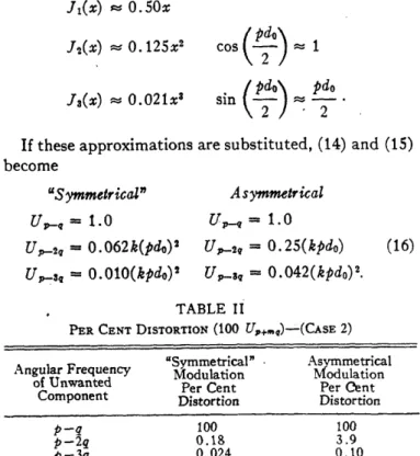
The second case may be of interest because of its pro-posed use in television sound channels." The average pulse duration do is chosen 3.0 per cent, and d will be varied from 0.5 to 5.5 per cent of a period, corresponding to k =-0.83. Since do is small, the trigonometric and Bes-sel functions in (14) and (15) may be approximated as fol-lows with not more than 1 per cent error.
Jl(x) 0.50x J2(x) 0. 125x2 J3(x) 5 0.021x3 ( do) cos_ - 1 2 sin d n Pd 2 - - 2
merical example chosen, the duty cycle pdo/2r=0.03, and the modulation index k=0.83. Substituting these values in (16) yields the results listed in Table II.
"Symmetrical" pulse duration modulation is seen again to be superior in this case. The ratio of p to the highest value of q should be at least two in order to pre-vent the p-q component from falling within the pass band, or three if the p-2q component is also to be
ex-cluded.
Case 3
The third case may have direct bearing on multichan-nel pulse-position-modulation systems. This is so be-cause a conventional method of demodulation consists of generating asymmetrically duration-modulated pulses, one edge being formed by the synchronizing pulse and the other by the information-carrying pulse of the channel in question.
The quantity kpdo/27r is the ratio of maximum time shift to pulse-repetition period and may be about 0.01 or 0.02, regardless of the average pulse duration. The same approximation to the Bessel functions as in Case 2 may be used here, and the results are identical to those given by (16) for the asymmetrical case.
For a ten-channel system, using "1 per cent" pulses, a reasonable time-shift amplitude might be 2 per cent of the repetition period, so that each channel pulse covers
a range of 5 per cent. Table III gives the inherent
distor-tion for all channels. If these approximations are substituted, (14) and (15)
become
"Symmetrical" Asymmetrical
U-~ = 0 U1.0
U,,q - 0.062k(pdo)2 U, 2 = 0.25(kpd0)
U_,- = O.010(kpdo)2 Usa = 0.042(kpdo)2.
TABLE III
PER CENT DISTORTION (100 U,+,_)-(CASE 3) Angular Frequency of Undesired 100 U,,, Component pq 100 p-2q 3.15 p -3q 0.067 (16) TABLE II
PER CENT DISTORTION (100 U,+,)-(CASE 2) Angular Frequency "Symmetrical" Asymmetrical
of Unanted Modulation Modulation
of Unwanted Per Cent Per Cent
Distortion Distortion
p-q 100 100
p-2q 0.18 3.9
p-3q 0.024 0.10
These are general relations which hold whenever the above approximations are justified. For the specific
nu-These results lead to the following conclusions, if one assumes that ideal low-pass audio filters are used. In Case 2 (asymmetrical) and in Case 3, the ratio of pulse-repetition frequency to the highest audio frequency can be as low as two for Iow distortion, and three for negligi-ble distortion. In Case 2 ("symmetrical"), the distortion is negligible even for a ratio of only two, the theoretical limit mentioned in the introduction. Case 1, on the other hand, may call for somewhat higher ratios. Some of these results have been checked experimentally.
CvD
. . . . ~-- , " 1-" 1~'~_ _---~-
1235 1947