Direct-Write Assembly of Colloidal Materials
by MASSACHUSETTS INSTITUTE
OF TECHNOLOGY Alvin Thong Lip Tan
B.S., Northwestern University, 2011
M.S., Northwestern University, 2012
LIBRARIES
ARCH NES
Submitted to the Department of Materials Science and Engineering in partial fulfillment of the requirements for the degree of
Doctor of Philosophy in Materials Science and Engineering atthe
Massachusetts Institute of Technology September 2019
© 2019 Massachusetts Institute of Technology. All rights reserved.
Signature redacted
Signature of A uthor: ... ...
Department of Materials Science and Engineering August 16, 2019
Signature redacted
C ertified by : ... ...
Robert J. Macfarlane Assistant Professor of Materials Science and Engineering Thesis Reader
Signature redacted
C ertified by : ...Anastasios John Hart Associate sor of Mechanical Engineering
Signature redacted
ssupervisorC ertified by : ...
...---SDonald
R. SadowayProfessor of Materia( Science and Engineering Chair, Departmental Committee of Graduate Studies
Direct-Write Assembly of Colloidal Materials
by
Alvin Thong Lip Tan
Submitted to the Department of Materials Science and Engineering on August 16, 2019 in partial fulfillment of the
requirements for the degree of Doctor of Philosophy in Materials Science and Engineering
Abstract
Colloidal assembly, which is the spontaneous organization of nano- and micro- sized particles, is an attractive means to create materials with properties that can be engineered via hierarchy of particle composition, size, ordering, and macroscopic form. However, while there are well-established methods for assembling colloidal crystals as films and patterns on substrates, it has not been previously possible to build freeform colloidal crystal structures. Macroscale, freeform colloidal crystals could enable the development of novel composites, photonics, electronics, and new studies of crystallization in three-dimensions. This thesis describes the development of direct-write assembly, a process combining the bottom-up principle of colloidal self-assembly with the versatility of direct-write 3-D printing. Direct-write assembly is performed by precision
dispense of a colloidal suspension from a fine needle into a temperature-controlled environment. Using polystyrene particles suspended in water as a model system, we derive a scaling law that
governs the rate of assembly. Moreover, by high resolution motion control of the substrate, the trajectory of crystal growth, and therefore the shape of the crystal, can be controlled in freeform.
We show how to prevent cracking in these free-standing colloidal crystals, and demonstrate the emergence of structural color tunable by particle size. We also explore in-plane direct-write as a means for fabricating colloidal crystals patterned by a digital template. The kinetics of crystal growth can be modelled by the Dimitrov-Nagayama equation for convective assembly, which allows us to develop an operational phase diagram to serve as a practical guide for high-throughput assembly. Moreover, we develop a means of rapidly characterizing grain structure from the optical diffractive properties of the colloidal crystal. By sequentially sintering and overlapping passes, in-plane direct-write can potentially build up to 3-D structures. Finally, we consider the scaling of forces in the write assembly process and demonstrate that direct-write can be extended to various particle systems. In particular, we demonstrate application of direct-write to the assembly of colloidal silica, gold, and iron oxide supercrystals.
Thesis Supervisor: A. John Hart, Associate Professor of Mechanical Engineering
Thesis Reader: Robert J. Macfarlane, Assistant Professor of Materials Science and Engineering Thesis Committee Members:
Caroline Ross, Professor of Materials Science and Engineering Mathias Kolle, Assistant Professor of Mechanical Engineering, MIT
Acknowledgements
I would like to thank Professor A. John Hart for guiding my PhD. I have benefitted from his energy, enthusiasm, and encouragement in all areas of research, including formulating research ideas, designing experiments, discussing results, writing, and presenting. Working in his lab has been a marvelous experience, and I hope that others might have a similar experience working with me in future. In addition to John, I also received much valuable advice from my other thesis committee members: Professors Caroline Ross, Robert Macfarlane, and Mathias Kolle.
Second, I would like to thank John's Mechanosynthesis Group and our many collaborators. Mostafa Bedewy and Justin Beroz did some important early work before I joined the group. I thank Justin for his expertise in machine design, our wide-ranging discussions of interesting physics, and practical help in the many things that we worked on together. I also thank Ccile Chazot for listening to some of my outlandish research ideas and actually coming up with helpful suggestions.
When I got interested in structural color, John introduced me to Prof. Mathias Kolle, who helped me build depth in the area and was very generous in letting me work in his optics lab, even teaching me how to use some of the instruments himself. I enjoyed the support and company of the students in his group, and have been fortunate to collaborate with Sara Nagelberg in our analysis of iridescence using ping-pong balls.
Some of the classes that I took helped me build good foundation and perspective for my thesis work. In particular, Prof. Daniel Blankschtein's class on colloids and Prof. John Bush's class on fluid mechanics helped me think lucidly about my experiments. Prof. Eugene Fitzgerald helped me formulate perspective on doing innovative work. I thank them for their world-class
instruction.
I am indebted to undergraduate and high school researchers who have assisted in experiments
and data analysis: Elizabeth Chang-Davidson (MIT), Joel Tan (SUTD), Benjamin Liu (Arcadia High School), Daniel Shkreli (MIT), and Johan Villanueva (MIT). Thank you for working with me and contributing to this work. It has been a privilege being your grad mentor.
I thank my family and friends: My parents were my first teachers, and encouraged me to broaden
my horizons. Some of the tinkering in home-made experiments with my brother probably translated to useful lab skills. At MIT, I was fortunate to be a part of communities outside the lab, such as Burton-Conner House, Sidney-Pacific Graduate Community, the Addir Fellows, and the Lutheran-Episcopal Ministry. I also thank the MIT Spinning Arts Club and MIT Skydiving Club for healthy forms of recreation that keep me in peak physical and mental condition.
This research was supported by the National Science Foundation CAREER Award
(CMMI-1346638, to A.J.H.) and by the MIT-Skoltech Next Generation Program. Additionally, I thank
Contents
1
Introduction and B ackground... . 71.1 Hierarchically structured materials ... 7
1.2 Evaporative self-assembly ... 8
1.3 Direct-write 3-D printing ... 14
2 Freeform direct-w rite assem bly ... . 17
2.1 Direct-write assembly of freestanding colloidal crystals... . 17
2.2 Kinetics of assem bly ... 21
2.3 Freeform assembly... 24
2.4 Optical properties... 24
2.5 Cracking control... 26
2.6 Conclusions... 32
2.7 Experim ental details... 32
2.8 Supporting Inform ation... 39
3 In-plane direct-w rite assem bly... . 53
3.1 In-plane direct-write assembly of patterned colloidal crystals ... . 53
3.2 Kinetics of in-plane assembly ... . 56
3.3 Effect of toolpath ... 59
3.4 Optical properties... 63
3.5 Conclusions... 67
3.6 Experim ental details... 69
3.7 Supporting Inform ation... 71
4 G eneralizing direct-w rite assem bly ... . 76
4.1 General scaling of forces in direct-write assem bly... . 76
4.2 Direct-write assembly of non-polym er particles... . 82
4.3 Direct-write assem bly with non-aqueous colloids... . 84
4.5 Supporting Information... 96 5 C onclusion and O utlook... 99
5 .1 S u m m ary ... 9 9
5.2 Future opportunities ... 99 6 R eferences ... 102
1 Introduction and Background
This chapter uses some text originally writtenfor thefollowingjournal articles.
1. Tan, A. T. L.*; Beroz*, J.; Kolle, M.; Hart, A. J. Direct-Write Freeform Colloidal
Assembly. Adv. Mater. 2018, 30 (44), 1803620.
2. Sharma, M.*; Tan, A. T. L.*; Smith, B. D.; Hart, A. J; Grossman, J. C. Hierarchically Structured Nanoparticle Monolayers for the Tailored Etching of Nanoporous Silicon. A CS Appl. Nano Mater. 2019, 2 (3), 1146-1151.
*Equal contribution
1.1 Hierarchically structured materials
Structural hierarchy-which involves the control of composition and form across length scales-is a powerful strategy for creating functional natural and synthetic materials. In natural materials, examples of hierarchical morphology can be found in, for instance: butterfly wings, which display intricate photonic effects;1 the xylem architecture of plants, which feature optimized mass transport 2 and the skeletal structure of sea sponges, which possess outstanding mechanical properties.3 In synthetic materials, colloidal particles can be assembled into crystals that exhibit unique optical,5 chemical,6'7 and mechanical89 properties based on particle geometry,
composition and arrangement. Colloidal assembly therefore enables materials design for diverse applications including optical coatings,10 biological and chemical sensors," and battery
electrodes.12
Self-assembly can also be performed on colloidal particles of various geometries to attain emergent properties and functionalities. Seminal work by Vlasov et al.5 (Fig. 1.1a) has shown
~-~~ffi4
that assembled arrays of silica microparticles demonstrate a photonic bandgap, a property that arises due to the periodicity of the crystal lattice, rather than the individual particles themselves. Self-assembly can also be performed on colloidal particles of other geometries to attain emergent properties and functionalities. For example, Fig. 1.1b shows an array of aligned silver nanowires assembled by the LB technique. Each silver nanowire has a diameter of approximately 50 nm and aspect ratio of 50. The array of aligned silver nanowires collectively function as excellent substrates for surface enhanced Raman spectroscopy (SERS). IEven more recently, it has been possible to assemble colloidal particles into non-planar structures. Confinement of colloids within liquid droplets and assembly upon evaporation yields spherical clusters of particles, such as photonic "balls" (Fig. 1.lc) for optical applications such as visual displays 14-18 and crumpled
balls of graphene for energy applications such as electrochemical storage.19-2 1
C
Figure 1.1. Examples of colloidal assembly. (a) Silica colloidal crystal assembled by evaporative assembly from Ref. 22 (b) Silver nanowires aligned by Langmuir-Blodgett Assembly from Ref.
13, (c) Polystyrene particles assembled into a photonic ball from Ref 2.
1.2 Evaporative self-assembly
Colloidal particles can be directed by intermolecular and surface forces, and thus self-assemble into larger aggregates. Thus, self-assembly provides a pathway to establish hierarchy in colloidal
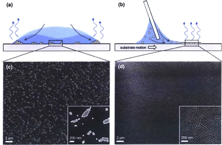
assembly.2 4 2 5 However, the assembly of colloidal particles into a structure of well controlled geometry is non-trivial, even for a simple geometry such as a uniform film. Indeed, the common phenomenon of a drying drop of coffee provides a case in point. One might consider coffee as a colloidal suspension with the coffee grinds as the particulate phase and water as the fluid phase. When the droplet is left to dry, instead of forming a uniform film, the coffee dries as a ring stain (Fig. 1.2a) due to capillary flows that preferentially transport the coffee particles to the edge of the droplet (Fig. 1.2b). The result is thick deposit of particles at the edge of the droplet and sparse deposits in the middle of the droplet, as illustrated in Fig. 1.2b.
ab
Figure 1.2. The coffee-ring effect. (a) A 2-cm-diameter drop of coffee containing 1 wt% solids that has dried to form a perimeter ring, accentuated in regions of high curvature. (b) Spheres in water during evaporation, as described in the text. Multiple exposures are superimposed to indicate the motion of the microspheres. Reproduced from Ref. 26.
Nevertheless, there are techniques that, through planar confinement in the evaporative process, yields large area films suitable for applications such as electronics and optical displays.
Such techniques include dip-coating, Langmuir-Blodgett drawing, 27,28 and blade-casting 29,30. In my own work, I have utilized blade-casting as a means for assembling nanoparticles into a two-dimensional monolayer array. In blade-casting, a blade is used to stretch the meniscus of a colloidal suspension laterally across the substrate, resulting in uniform evaporative self-assembly at the trailing edge of the meniscus, as illustrated in Fig. 1.3. Blade-casting, and other similar methods, are an attractive means for scaling up the self-assembly of colloidal particles into films.
(a) (b)
0 o
Figure 1.3. Evaporative self-assembly by drop-casting and blade-casting. (a) Illustration of drop casting, where evaporation is highest at the edge of the droplet, resulting in thick 'coffee ring' deposits at the edge and sparse particle islands at the middle of the drop. (b) Illustration of blade-casting, where a blade is used to draw the meniscus laterally across the substrate, resulting in uniform evaporative self-assembly of particles at the trailing edge. (c-d) SEM of particle deposits formed by (c) drop-casting, and (d) blade-casting. Reproduced from Ref. 1
It is possible to create patterned films, i.e., film structures of higher order complexity, by manipulation of wetting phenomena. Here, we look at two examples in the literature. Masuda et
al.32 demonstrated that, by first treating a silicon substrate with a hydrophobic self-assembled
monolayer (SAM), one could cause an oscillatory slip-stick motion of the contact line while colloidal particles assemble onto the substrate, as shown in Figure 1.4. The result is an array of colloidal particle stripes, assembled perpendicular to the drying direction. Conversely, one could create an array of stripes parallel to the drying direction. Huang et al.33 reported the formation of metal nanoparticles stripes on a hydrophilic substrate by harnessing a fingering instability at the contact line, as shown in Figure 1.5.
a conecdion current OTS-SAM cedingWater ~20t evaporation evaporation 00U 0 0 0 0 00-70-8ot 000 30X10mm O 0 OO 00 ethanol: 50 ml, O
SiO2 particles (1u m 0): 30 mg
Sooum2p
Figure 1.4. (a) Schematic for self-assembly process to fabricate an orderly array of particle wires constructed from a close-packed structure. (b)-(d) SEM micrographs of arrays of particle wires. Adapted from Ref. 32
In my own work, we have used the blade-casting platform to harness both slip-stick
motions and fingering instabilities to create a variety of film patterns. As shown in Figure 1.6, by blade casting a dilute suspension (6.7 x 10¹² particles/mL) of
10-nm
gold core particles at low blade speeds (0.002 mm/s), slip-stick motion is dominant and stripes perpendicular to the drying direction is obtained. At higher speeds (0.015 mm/s - 0.1 mm/s), a fingering instability causesthe stripes to become webbed, and at very high speeds (0.15 mm/s), sparse clusters of nanoparticles form.
ci
a
*t
0 a a 13Figure 1.5. a-d, A schematic drawing illustrating the formation of an aligned gold nanoparticle
stripe pattern by vertical deposition (a,b). Only the nanoparticles at the water-substrate contact line (gold dots in b-d) are shown for clarity. The substrate is raised slowly (a,b) so that water is evaporated when a new surface is exposed. The 'wet' contact line containing uniformly
dispersed nanoparticles breaks up into aggregates of nanoparticles (b,c) owing to the fingering instability during the initial dewetting stage. These fingertips then guide further deposition of nanoparticles, finally forming the extended stripe pattern (d). e, Direct optical microscopy
observation of the water front reveals a rapid motion of nanoparticles towards the wet tips (circled area) of the stripes as indicated by the arrows. This leads to the unidirectional growth of the stripes across the entire substrate as shown in the optical microscopy image in f. g, Silver nanoparticle stripes have been obtained in the same fashion. Reproduced from 3
g
80 4-0 C 0 15 (U L.. 4-CO cW o --, 0-<U 0 E 60 40 20 0 t 0 0 0.05 0.1 Speed (mm/s) 0.15 0.2Figure. 1.6. SEM images of blade casted silicon produced using substrate speeds of (a) 0.002 mm/sec, (b) 0.015 mm/sec, (c) 0.02 mm/sec, (d) 0.05 mm/sec, (e) 0.1 mm/sec, (f) 0.15 mm/sec. Scale bars represent 10 pm. (g) Plot of area fraction of monolayer against blade speed, as obtained by image analysis of SEM images. Reproduced from 3
These, and other established techniques for evaporative self-assembly, enable the organization of nanoparticles over large areas. We note, however, that these techniques are limited to thin films on substrates and the assembly of nanoparticles into out-of-plane structures remains a challenge.
1.3 Direct-write 3-D printing
Another emerging fabrication technique, direct-write 3D printing, has been used to build
miniature antennae, 3 4lightweight composites," batteries,3 6 and many other functional structures from metallic, dielectric, polymer, and biomaterial inks. In direct-write printing, an ink is provided to a needle or nozzle, which is moved with respect to a substrate as the ink is extruded. The rheology of the ink is typically engineered to give it a well-defined yield stress, therefore requiring cohesion between particles in high-density suspensions,37 and enabling intricate
freeform structures to be built.
Fig. 1.7a shows work by Lewis et al. performing direct-writing of colloidal silver on a
hemispherical surface.3 8 The concentration of silver particles in the ink is high and the particles form a percolated network within the dried ink. Therefore, each ink trace constitutes an
electrically conductive path. Direct-writing of the silver ink into serpentine patterns creates a new functionality beyond electrical conductivity: An electrically conductive trace fashioned into such a geometry can be used as an antenna. Since the shape and periodicity of the serpentine
trace can be directly controlled by a computer, various antenna designs can be readily fabricated and optimized towards various frequencies and bandwidths.
Direct ink-writing has also been demonstrated as an enabling technology for biomedical
applications39,4 0, such as creating artificial blood vessels41. The example shown in Fig. 1.7b is a
hydrogel with fluidic channels in its interior mimicking branched blood vessel networks. The channel networks were fabricated from a template created by direct ink-writing. This example is noteworthy for its creative use of direct writing as a templating technique to create complex
inverse structures.
Direct-ink writing has also been used to create new materials with enhanced properties. Fig. 1.7c shows a graphene aerogel fabricated by direct writing graphene-laden ink into microlattice architecture. While random porous network aerogels can be readily created with bulk processing techniques, Worsley et al. have shown that, by using direct-write extrusion to fabricate aerogels of a designed architecture, mechanical properties such as the Young's modulus can be improved
by an order of magnitude compared to bulk graphene aerogels of comparable geometric
5 mm
Figure 1.7. Emerging applications of direct write extrusion: (a) Conformal patterning of
antennas from Ref. 38 (b) Templating artificial blood vessels in a hydrogel matrix from Ref.
(c) Fabrication of graphene aerogel, from Ref.42
Nevertheless, due to the need for specific ink rheology, direct ink writing does not allow long range crystalline ordering in the final structure.43-" If crystalline order can be achieved using colloidal building blocks in a direct-write process, emergent properties such as photonic 45 and
electronic band gaps,46 could be achieved.
Extending colloidal self-assembly to three dimensions would enable new applications uniquely enabled by macroscale colloidal crystals with complex geometry.
2 Freeform direct-write assembly
The workpresented in this section was ajoint effort withfellow graduate student Justin Beroz. The methods, procedures and construction of the experiment apparatus were developedjointly between us. The modelling effort, particularly on cracking of colloidal crystals, is credited to Justin Beroz. I designed andperformed most of the experiments, including sample fabrication, microstructural characterization, optical characterization, image processing and analysis. X-ray Microscopy measurements and analysis were performed by courtesy of Dr. Stephen Kelly of Carl Zeiss X-ray Microscopy, Inc. This chapter uses text originally writtenfor the followingjournal articles:
1. Tan*, A. T. L.; Beroz*, J.; Kolle, M.; Hart, A. J. Direct-Write Freeform Colloidal
Assembly. Adv. Mater. 2018, 30 (44), 1803620.
2. Beroz, J.*; Tan, A. T. L.*; Kamrin, K.; Hart, A. J. Crack-free colloidal crystal macrostructures. In preparation.
*Equal contribution
2.1 Direct-write assembly of freestanding colloidal crystals
By combining principles from direct-write 3-D printing and colloidal self-assembly, we can
create materials with hierarchical complexity and order. In this chapter, I discuss the development of a new fabrication technique - direct-write assembly - that combines the
principles and advantages of evaporative colloidal assembly with the versatility and scalability of direct-write 3D printing. This approach allows for both local control of particle organization, and global control of the shape of the structure.
a
b
Particle Needle later 0 Liquid 0 0 bridge Particle structure Substrate Particle Heated structure plates Substrate 20pm 1c
d
grain boundary vacancy screw dislocationFigure 2.1. Direct-write assembly of macroscale freestanding colloidal crystal structures. a)
Direct-write assembly is performed by precision dispensing of a colloidal solution from a fine needle, followed by controlled downward or multi-axis substrate motion to build the structure, as shown in the schematic (top) and in the photograph (bottom). Scale bar: 2 mm. b) Scanning electron microscopy (SEM) image of a freestanding structure comprising of particles of radius a = 500 nm. Insets: close views of top and middle sections. c) Three-dimensional reconstruction of the interior of a freestanding colloidal structure, as imaged by X-ray microscopy. d)
High-magnification view of a portion of the cross-section indicated in (c), revealing crystal defects such as vacancies, dislocations, and grain boundaries.
Direct-write assembly is performed using a custom-built apparatus wherein a colloidal solution is dispended through a needle, with fine position control relative to a substrate, in a temperature-controlled environment (Figure 2.1a and Figure S2.1). The formation of a colloidal structure is initiated by dispensing a small amount of suspension to form a liquid bridge between the substrate and the orifice of the needle. This liquid bridge provides confinement for the assembling particles that accumulate at the base of the liquid bridge. In turn, we observe accumulation of particles into a solid layer at the base of the liquid bridge and retract the
substrate downward as the particles accumulate. Continuing, we move the substrate downward at a rate matched to the vertical growth rate of the particle structure; this enables construction of high aspect ratio vertical structures (Figure 2.1), which we call colloidal "towers". The formation process can be terminated at any point by halting the flow from the needle, after which
evaporation collapses the liquid bridge (Figure S2.2); freestanding structures several millimeters tall can be easily drawn. The dispense rate (~10' pl/s) and translational motions of the substrate relative to the needle (~1 m/s) are motor controlled, and the needle, tower, and substrate are viewed in situ with video microscope cameras.
The radius R of the colloidal towers is nominally set by the needle radius, and the local width and curvature of the structure can be modulated by changing the dispense rate relative to the vertical rate of motion, as shown in Figure S2.3. When the dispense rate is lesser than the rate of evaporation, the liquid bridge necks, as shown in region (i). When the dispense rate is greater than the rate of evaporation, the liquid bridge bulges, as shown in region (ii). The result is a
structure of varying cross section, as exemplified by the 'hourglass' structure shown in Figure S2.3. mmg- --5 4-3 2
Figure 2.2. Exemplary milimeter- scale structures built by direct-write assembly. Optical and
corresponding SEM images of vertical columns built from a,d) a =500 nm polystyrene particles, b,e) a =250 nm polystyrene particles, cf) a =88 nmpolystyrene particles.
As afirst model system, we built colloidal towers using aqueous solutions of spherical
0.025. The diameters of the resulting towers range from 50 pm to 1 mm, and the heights range
from 1 mm to 1 cm, as shown in Figure 2.2 and Figure S2.4.
Throughout this wide range of dimensions, colloidal towers built by direct-write assembly are polycrystalline, though the packing of the smallest particles (a = 44 nm) is less ordered due to broad size dispersity (CV= 11%). X-ray microscopy permits non-destructive imaging of the particle arrangement within the structures. A three-dimensional reconstruction of an exemplary tower reveals an average grain size of approximately 20 tm (Figure 2.1c). A cross sectional slice of the imaged volume reveals grain boundaries, voids, and dislocations (Figure 2.1d), as can be expected within colloidal crystals.4 7
2.2 Kinetics of assembly
In situ video microscopy reveals that the colloidal towers precipitate wet, i.e., saturated with
water between the particles, and then dry at a distance L below the bottom of the liquid bridge. The "wet" and "dry" sections, as well as a drying front in between, are easily distinguishable based on optical appearance - the wet section is darker than the dry section, and the drying front
is opaque white (Figure 2.3a). The precipitation of the solid structure occurs by an influx of water and particles through the bottom of the liquid bridge. The water flowing into the wet section compresses the particles downward while the capillary pressure at the section's outer surface, due to the liquid's surface tension y, provides lateral constraint. This capillary pressure drives water through the wet section to its outer surface, where the water evaporates. The water experiences a resistance to flow due to its viscosity y as it travels in the interstitial spaces
between the particles packed at volume fraction
#2,
driven locally by the pressure gradient VP. In all our experiments, the Reynolds number is Re _ 103, based on the dispense rates and particle sizes. a 9, 9, 9, 9, 9, 9, I .4 .4 .4 V I / b M ~L 3 2 0~~ 'VC 22 0.2 0.3 Oj AO:)YaV+( [-1p mls) 0.4Figure 2.3. Scaling of build rate in direct-write colloidal assembly. a) The structure (radius R) precipitates wet, and evaporation occurs from the surface of the wet section of length L, which drives an influx of liquid and particles through the liquid bridge. Scale bar: 200 pm. The inset illustrates particles of radius a near the surface of a wet region of the solid, and the surface tension quantities on the air-liquid (y), air-particle (yap), liquid-particle (yp) interfaces. b) The
steady state build rate i follows a simple scaling relationship with y, a, L, the volume fraction of particles in the suspension
#i,
volume fraction of particles in the solid#2,
and viscosity of waterp. Calculation of error bars is detailed in Supporting Information.
A quantitative understanding of the factors governing the build rate in direct-write assembly was
obtained by performing a series of experiments where vertical structures of constant radius R were built with various particle radius a. Experiments are performed with polystyrene spheres suspended in water, where the polystyrene particles occupy volume fraction
#P~0.025.
a
01 1
For steady build of a vertical structure with uniform radius R, the wet length L is constant and the speed at which the substrate is withdrawn from the needle to build the structure i relates to the above-mentioned quantities as follows. The energy change dewetting a particle of surface area A, is U = (Yap - Ylp)A, = y cos 6 A, as its surface energy changes from liquid-particle yi, to
air-particle Yap; here Young's law Yap - Yip = y cos 0 defines the contact angle 0. The free energy change associated with dewetting a differential layer dz of the structure is therefore dF =
(u#2/Vp)R
2dz, V, being the volume of a particle, and
#2
being the volume fraction of particlesin the wet solid. The pressure difference PF of the liquid relative to atmosphere at the drying front is the negative change in free energy per cross section area PF = -(dF/dz)/wR 2 _
#
2 Y cos 0 /a.We assume that the average flux of water q through the liquid bridge into the structure is governed by Darcy's law q = (-k/p)VP, where the permeability of the structure k must, on dimensional grounds, be of the form k = f(#2)a2 and using the Kozeny-Carman equation 48 we
approximate f(#2) ~ (1 -
#2)3/45#2
.The pressure at the top of the structure is set by thecapillary pressure of the liquid bridge PB-y/R, so VP - 2 CoS a by 1, and the build rate of the structure is therefore
C 01f($2)ra Eq. 2.1
(1-$1j)yt
Mass balance gives q = 202(1 -
#1)/#1, #
2 = 0.73 based on X-ray microscopyExperimentally, C ~ 22 for all structures we built to heights > L (Figure 2.3b). Equation 2.1 fits the data well, for a plurality of experiments with particle sizes ranging from a = 44 nm to a = 110 nm, resulting in a growth rate of~0.5 - 3 tm/s. The build rate is inversely proportional to L
because a shorter L means a greater pressure gradient and therefore greater flow by Darcy's law. The intuition that a longer wet section implies a faster build rate - that is, more surface area
implies greater total evaporation and greater flow rate through the needle - is true only for
structures built to heights shorter than L.
2.3 Freeform assembly
Complex freeform shapes can be built by coordinating additional degrees of freedom in the substrate's motion. For example, to form a helical structure, we coordinated the curvilinear rate of growth of the structure with the rotational and vertical motion of the substrate, as illustrated in Figure 2.4b. Here, a slanted-tip needle was used so that the liquid bridge would be oriented in the direction of crystal growth, as shown in Figure S2.6. The helical structure shown in Figure 2.4b has a pitch of 2.28 mm, circular radius of 0.34 mm, and is built from polystyrene particles with a
= 44 nm.
2.4 Optical properties
Colloidal assemblies exhibit a diverse range of optical phenomena depending on their crystalline order. Well-ordered colloidal crystals are known to have photonic stopbands that enable the spectrally-selective reflection of light,4 950 which gives a sparkling, iridescent appearance. The spectral position of the stopband mainly depends on the particle size and packing.18 Conversely,
amorphous colloidal structures made by frustrating the assembly process 5can exhibit
non-iridescent structural colors, and the building blocks can be chosen to exploit absorption and interference effects synergistically.5 2-5 4 Such ordered and disordered materials can form the basis
for lasers, optical sensors, waveguides, and structural color displays. a
I
ri
a 96 rvn a 10 rn azl10mn a 140 vn as110 nm a* 140 nm 0.8 0.6 04 02 b 400 450 500 550 600 650 700 Waveength [nmiFigure 2.4. Tailoring the properties of freeform colloidal structures by choice of particle size, build trajectory, and material. a) Freestanding cylindrical colloidal crystals with structural colors tunable by the radius of polystyrene particles (increasing from left to right), and corresponding reflectance spectra measured from the surface of each of the above structures. b) Optical image of a freestanding helical shaped structure, with circular diameter of approximately 0.67 mm and height of approximately 1.1 mm. The helical structure was built by simultaneously rotating (o) and lowering (v:) the substrate.
Direct-write assembly therefore provides a route to build macroscale colloidal structures with tailored optical properties, such as by selecting the particle size and controlling the packing within the structures. The ordered crystalline arrangements observed in the interior of our
structures (Figure 2.1c and Figure 2.1d) suggest that they should exhibit structural coloration due to Bragg reflection occurring in the visible range of light. Structures made from monodisperse
particles of different size should therefore reflect different colors when illuminated with white light. Upon white light illumination, towers formed from particles of radius a = 95 nm, 105 nm,
110 nm, and 140 nm appear violet, blue, green, and red, respectively, as shown in Figure 2.4a.
Reflectance spectroscopy reveals that the towers exhibit Bragg reflection peaks at k = 420 nm, 460 nm, 510 nm, and 620 nm, respectively. In towers built from suspension with mixed particle sizes (here, an equal proportion of a = 110 nm and a = 140 nm particles; Figure 2.4a), the slight mismatch in particle size leads to frustrated particle packing and no long-range order. Therefore, under white light illumination in an optical microscope, the mixed-particle towers appear whitish and reflectance spectroscopy shows that all visible wavelengths have been reflected at a uniform level of ~0.2. The emergence of structural colors from ordered assemblies of particles, and the tuning of particle size to modify the spectral position of the reflectance peak, is a
well-established strategy for planar colloidal crystals, which we have now demonstrated can be realized in complex, macroscale shapes via direct-write assembly.
2.5 Cracking control
Interestingly, we find that cracks may be present or absent in these freestanding structures depending on structure dimensions and particle size. The established treatment of a liquid-saturated colloidal solid is as an elastic continuum material that, when compressed by a capillary pressure at its outer surface, shrinks volumetrically during drying in a manner analogous to thermal contraction 6. In drying colloidal films, a no-slip boundary condition with the underlying substrate is said to be responsible for generating tensile stress in the film, causing cracks57 . However, the external surfaces of our particle structures are free boundaries; in fact, we have
built structures with cracks only at the top. The presence of cracks is therefore curious from this point of view and suggests a different physical explanation.
Time [sec] 20 40 60 80 100 V Yap YP i 0 i 0.5 Az/L
Figure 2.5. The radial change of a thin cross-section layer of the structure AR, relative to its final radius R when dry, exhibits the same contraction and expansion behavior in two cases: (i) during
construction, as a function of the layer's distance below the bottom of the liquid bridge Az; (ii)
at termination, as a function of time. Cracks appear in the sections labeled by 1, which for both curves correspond to AR =0 (large white-filled markers) ahead of the drying front (shaded regions); the data points are an aggregate of 10 layers that each develop a crack and the solid lines are moving averages. All measurements are from the same structure, a = 44 nm (additional measurements in Supplementary Fig. S2.8). Scale bar represents 500 pm
The cracks vary in width and orientation (Fig. 2.6a, Fig. S2.6); however, we generally observe that the widest cracks are preferentially circumferential and typically visible in situ with the video microscope cameras (Fig. 2.5). These circumferential cracks appear in the wet section just above the drying front during construction (Fig. 2.5(i)), and throughout the entire wet section during evaporation of the remaining liquid after construction is terminated (Fig. 2.5(ii)). In both cases, the cracks appear when the structure's radius constricts to ~ R .
0 4 3 0 0 x 1 a 0I -1 0
1-At the moment these cracks occur, we estimate the capillary pressure exerted on the particles is primarily borne by particleparticle contacts because other forces experienced by the particles -namely viscous, electrostatic, Van der Waals, and thermal - are smaller by at least an order of
magnitude (Figure S2.7). Because the radius is ~ R, as a lowest order approximation we assume the structure here is unstrained and ignore the elastic strain energy in the particles as if they are hard spheres. This leaves only energy quantities related to the liquid and wetting of the particles, and we proceed by considering the cylindrical section of the structure with radius ~ R and height
I just before it initiates a crack; / will be interpreted later in the context of building a structure
and at termination of build. This section comprises contacting particles saturated in stationary water at uniform pressure difference P from atmosphere due to the microscopic water menisci wetting the particles at the section's outer surface as depicted in Fig. 2.5 (inset); the surface energies y,y,,Y P correspond respectively to surface areas A, A,,, A,, .
In a differential time interval, a differential volume of water dV evaporated from the section's outer surface in turn may deform and recede the menisci between the particles so that the differential change in free energy for the section is
dF =-PdV+ydA+,dA,,+yPdA,=-PdV+y(dA+cosdA,). This is simplified againusing Young's
law and recognizing that dA, = -dA, >o because the water may recede to expose more air-particle surface at the expense of liquid-air-particle surface.
If the particles are immobile, then the water is in equilibrium and dF = 0, so that
-PdV < 0 because P, dV < 0 , is equal to the energy acquired creating surface area by deforming and receding the menisci between the particles. By a scaling argument (Supplementary
Information), we may substitute -PdV-* -cIrA, and r(dA +cosOdA) -> c2A,, which recasts the
equilibrium equality as -cirA, +c2
rA,
=0 where c, / c, =1; A= 2R is the section's outer surface area and the factors c, are positive functions of geometry and 0.The particles cannot, in actuality, all be immobile because some must separate to form a crack. If the particles have a collective mobility such that within the differential time interval they may rearrange to occupy a slightly smaller overall volume - a reasonable supposition based on Fig.
2.5 - this lowers the free energy of the section because not all the energy expelled in the
evaporated volume is consumed as surface energy in deforming and receding the water menisci. Here -crA, +cyA, and therefore c, / c1, where the ratio c, / c, is a metric that indicates the amount of particle mobility in the sense just described.
For initiation of a crack to be energetically favorable, the same inequality must be satisfied including an additional consumption of surface energy on a characteristic area A, associated with initiating the crack; this gives -cirA4 +crA, +,cA, < 0, where the factor c, on the crack initiation
term is similar to c2 . It must be that A, a2 because a crack can only propagate if the section can
at least overcome an energy barrier on the order of bringing a particle to or from its outer surface. Rewriting the inequality as c(c, /c -)/c>/, A,/,, evidently for a given particle size
immobile particles, i.e., c, /c, =1, is cracking impossible. Conversely, for a given particle size the section may be crack free provided its surface area is sufficiently small. Succinctly, the section cracks when satisfying
2
a
RI Eq. 2.2
The parameter g depends on contact angle 0, particle mobility c, /c, and geometry, where g 0
and g =0 for immobile particles. In this way, the section can develop a crack despite being
compressed by a uniform capillary pressure. This result is a ratio of length scales due to having only considered the dominant wetting energy terms.
a C 00 0 1D0O @O L 0 10'AA * •
HW
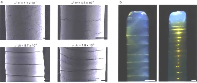
12 10 '6 4 2 S 00• •* 104 10" 104 0 WIa 10 ga3-10 1 2 3 RH Ipm2| 4 5 6 X101Figure 2.6 Conditions for crack development. (a) Optical images of the top section of particle
structures exhibiting (i) wide circumferential cracks, (ii) shallower cracks in arbitrary
orientations, and (iii) no cracks, where the structure internally reflects the illumination incident from the top right. (b) For all structures we built, the dimensionless number a2/Rl demarcates the
three cases, corresponding to (i) white, (ii) grey, and (iii) black data points. (c) Measurements of the spacing H between circumferential cracks provides an upper estimate on a2/Rl for the onset
of cracking, denoted by the dashed line in (b). Scale bars represent 50 pm for the optical images and 5 pm for the SEM images.
The height / corresponds to the section of the particle structure with its radius constricted to ~ R. According to Fig. 2.5, during construction this is the section with some height 1 < L just above the drying front (Fig. 2.5(i)) and at termination it is the section 1;~ L at the top (Fig. 2.5(ii)); for
il
structures built to heights < L due to the limits of our experiment apparatus, at termination, I is the structure's height. According to Eq. 2.2, this means that cracks are most likely to initiate at the top of the structure, and L determines the maximum likelihood of a structure initiating a crack. For all structures, the quantity a2/R ~1, using the maximum values for 1, i.e., / equals L or for shorter structures their height, demarcates those with and without cracks after drying (Fig.
2.6b). For the subset of structures with wide circumferential cracks, the sections in between the
cracks have area A, ~ RH (Fig. 2.6a left) which approximately saturate Eq. 2.2, and we find g ~ 3 x 10⁻⁷ (Fig. 2.6c). The measurements of H were taken only from the top parts of the
structures where the cracks formed at termination throughout the remaining wet section of length » H , which ensures an approximate upper estimate for g (Fig. 2.6b, dashed line).
The fact that we can identify an approximately constant value for g indicates that the particle mobility c, /c2 is approximately constant at the moment of crack initiation, and g « I presumably
indicates c /c2 is nearly unity which agrees with our picture of the particles just contacting one
another in their close-packed arrangement when the section's radius is ~ R. Interestingly, there is a transition between shallower cracks in arbitrary orientations (Fig. 2.6b, grey circles) and wide circumferential cracks (Fig. 2.6b, white circles) about a2/RI ~ 2x10⁻⁸; this perhaps indicates that particle mobility becomes directional, although the details of crack propagation are beyond our free energy argument for crack initiation. Combining Eq. 2.1 and Eq. 2.2, structures built at rates
> gC#, f (#2)yR are crack free. The construction of crack-free structures is important to future pa
2.6 Conclusions
We have demonstrated the combination of evaporative self-assembly with a direct-write process, enabling the freeform construction of macroscale colloidal crystalline solids for the first time. Looking forward, we anticipate this technique can build colloidal materials with tailored optical,
58,59 mechanical 60,65 and acoustic 66 properties, and many other interesting emergent
characteristics. Our technique may also serve as a model system to investigate meniscus-confined colloidal epitaxy 67, and to build macroscale structures with a single crystallographic
orientation. Direct-write assembly may also be applied to particles with even smaller sizes and from a wide range of materials, thereby combining materials design via self-assembly with the versatility of direct-write 3D printing.
2.7 Experimental details
Liquid dispensing apparatus. We built particle structures using a custom-fabricated benchtop
system that comprises a glass syringe and needle mounted vertically above two parallel aluminium plates that create a uniform temperature environment for the particle structures (Figure S2.1). The needle passes through a hole in the top plate, which we machined in half to expedite preparation for experiments, and the substrate rests on the bottom plate as shown. The top and bottom plates are uniformly heated by thermoelectric chips (standard square dimensions, Custom Thermoelectric), and the plate temperature is measured by embedded thermocouples (K-type) which feed to a temperature controller (PTC 10, Stanford Research Systems). The
thickness of the top plate was chosen so that the particle suspension dispensed through the needle heats to the temperature of the plate while transiting its thickness for the dispense rates used in
experiments. The dispense rate (~0.01 l/s) and translational motions of the substrate relative to the needle (A1 pm/s) are motor controlled (0.078 m step size: M-229.26S, Physik Instrumente), and the motors are controlled manually using joysticks (Pro Flight Throttle Quadrant from Saitek); we found this to be the most convenient way to match the structure's evaporation and build rate, and enable fine adjustments. The motions of all the actuators are recorded for the duration of each experiment. Depending on the volume capacity of particle suspension required to build the structures, we used syringes with piston diameters [2.30, 3.26] mm which
respectively correspond to dispensing precisions of [0.3, 0.7] nl. The dispensing needles were made of glass for smaller sizes, ID/OD = [50/80, 82/120, 200/250, 400/500, 600/700] pm (Hilgenberg), and made of stainless steel for the largest size ID/OD = 0.84/0.127 mm. The diameter of the structures we built were approximately the needle ID. We observe building of the particle structures in situ with two video microscope cameras. One views the needle orifice and liquid bridge with a 3X objective (Mitutoyo Telecentric 3X Objective, Edmund Optics stock # 56-985) and 5 megapixel CCD (DCC 1645C, Thorlabs). The other views the needle and entire structure with a IX objective (Mitutoyo Telecentric IX Objective, Edmund Optics stock # 56-984) and 10 megapixel CCD (EO-10012C, Edmund Optics). For each objective, the needle and structure are backlit with a telecentric lens (Techspec Telecentric Backlight Illuminator, Edmund Optics), and LED spotlights (Amscope LED-6W) are used to illuminate the front side of the structure facing the objectives. The video feeds from both CCD's are simultaneously recorded and displayed on a computer screen - we use the onscreen view to monitor the building of the
Microstructural characterization. Imaging the surface of the structures was performed with a
Zeiss Merlin SEM in high efficiency secondary electron imaging mode, at an acceleration voltage of 1 kV and probe current of 80 to 100 pA. X-ray Microscopy of the interior of the structure was performed courtesy of Dr. Steve Kelly of Carl Zeiss X-ray Microscopy, Inc. Zernike phase contrast images were acquired with a Zeiss Xradia 810 Ultra system, at photon energies of 5.4 keV and a total scan time of 25 hours. The field of view for data acquisition was
65 tm x 65 pm and the voxel size was 64 nm. Three-dimensional reconstruction of the image slices was performed with ORS Visual SI Advanced software.
Reflectance measurements. We constructed vertical particle structures, broke them at the base,
and mounted them on a flat adhesive substrate. The surface of the structure was illuminated through a microscope objective (Olympus, 20x objective lens, 0.4 N.A.) which also collected the light reflected from the sample. The reflected light passed through an optics train coupled to an optical fiber (Ocean Optics; 100-pm core) and was analysed with a grating spectrometer (Ocean Optics; Maya Pro) controlled via the software IGOR.
Surface tension estimates. Using our liquid dispensing apparatus, we drew particle suspension
into a needle (ID/OD: 0.6 / 0.7mm) and syringe from the supplier's bottle. We then dispensed the suspension through the needle (0.0417 mm3/s) and video-recorded the growing pendant drop, and used the video frame before the drop fell from the needle to calculate the suspension's surface tension by the pendant drop method. The vertical force balance on drop comprises gravitational F, surface tension F, capillary pressure F, and head pressure F, components:
O=F,+ +F,++F=-pVg + y27R - 'R + pghR2 .The expression for the surface tension is
pg(V-hfR)
therefore y= .(-R2)
2xrRO1- R/r )
Here, r is the mean radius of the droplet, R is the radius of the neck of the droplet pinned to the needle's OD, h is the distance from the needle to the centroid of the droplet, p is density of the droplet, and g is gravitational constant, and V is the volume of the droplet determined by image analysis.
The surface tension of particle suspensions from Polysciences was measured to be 73.0 ±2.0 mN/m, equal to pure water. However, the surface tension of particle suspensions from Bangs Laboratories was measured to be 56.6 ±1.1 mN/m. The lower surface tension is due to the residual surfactants, typically sodium dodecyl sulfate (SDS), from the particle synthesis process.
According to data from Lin et al. 68, a surface tension of 55 mN/m of SDS solution corresponds
to a surfactant concentration of 2 x 10⁻⁷ mol/cm 3. During construction of a particle structure, these surfactants are further concentrated by the evaporation of water. Approximately 98% of the volume of the particle suspension is evaporated in the tower building process, and we estimate the surfactant concentration increases to about 3 x 10⁻⁵mol/cm3, which exceeds the critical micelle concentration of 6.7 x 10⁻⁶ mol/cm3. Above the critical micelle concentration, the surface tension is 38.0 ±1.7 mN/m. Therefore, we assume the surface tension of the liquid during
73.0 ±2.0 mN/m for suspensions from Polysciences. We use this assumption when plotting the
data points in Figure 2.3b.
Radial change AR measurements. The radial changes of the structure were measured by image
analysis of videos, implemented in Matlab. A region of interest (~ 1.0 mm x 0.10 mm,
corresponding to 600 pixels by 60 pixels) was defined by its fixed distance from the substrate. Video frames were binarized using Sobel edge detection and the radial change was measured from the number of pixels between the detected edges. The reported radial change is the average radial change across the region of interest.
Zeta potential measurement. Electrophoretic mobility of particlespe was measured by phase
analysis light scattering (ZetaPALS Potential Analyzer, Brookhaven Instruments). Each
measurement was collected from 3 runs of at least 20 cycles with samples at room temperature T ~25 °C. The particles are suspended in deionized water at PH 7, i.e., 10-7 M ion concentration. The Debye-Huckel parameteris K = 10-6 [-1], so Ka <5 for our particles and the zeta potential is
calculated by =3 p, , where p and e are the dynamic viscosity and dielectric permittivity of 2 e
water, respectively. Surfactant is present in some of our particle suspensions sourced from one particular supplier (Bangs Laboratories), however we ignore this in estimating K. Zeta potential
measurements for each particle size are given in Table S2.1.
Particle volume fraction estimates in the structure. During construction, a layer of the particle
through the drying front. We observe that the final radius R of the structure once it is dry
corresponds to a close-packed arrangement of particles based on our SEM images of the particle structures after they are constructed. If we further assume that the particles remain in
approximately the same arrangement to one another once precipitated from the bottom of the liquid bridge and that the change in the structure's radius AR reflects a uniform volumetric change, then the expressions for the space s between the particles and particle volume fraction #2 as a function of AR/R are:
AR #0
s(AR/R)=2a
#2(AR/R)=;
R 1+AR/R'
# 0is the close-packed particle volume fraction when the structure is dry, as observed in our
SEM images. It is in the range pe =0.64,0.74] based on the ordering of the particles; $'°=0.64
corresponds to random close packing and #0°=0.74 corresponds to face-centered or hexagonal close packing. We measure AR/R ~ 0.01-0.05, so the initial space between the particles is a few percent of their radii.
Estimates of uncertainty. For all plots, the quantity plotted on each axis, say p(x,) which is a
function of the parameters x , we estimate to have uncertainty Ap(x,)= JAx, a, p(x,) .This is just
the magnitude of each term in the total differential for p(x,). The uncertainty estimates for parameters Ax, are given below for each plot.
In Fig. 2.3, the vertical axis quantity is ± and we take As to be the difference between the
were obtained by image analysis of the in situ optical microscopy videos. The horizontal axis quantity is )(0,(#2)1-0,)pL . According to the manufacturers for the particle suspensions
A$, =0.01 and A$, =0.001 based on the X-ray microscopy. For particle suspensions from
Polysciences Inc., Ay =2mN/m is the standard deviation of the surface tension measurements we performed by the pendant droplet method; for particle suspensions from Bangs Laboratories, we use Ay =1.7mN/m , according to measurements performed by Lin et al 68. Aa was taken to be the
standard deviation of particle radius as reported by the manufacturers of the particle solutions.
Ap was taken as 2.7 ptPa, 2.0 Pa, 1.8 Pa, for temperatures of 50 °C, 70 °C, and 80 °C,
respectively, as reported in reference data by Kestin et al 69. AL is the length of the drying front located at the end of the wetting length, measured by image analysis of the in situ optical microscope videos.
In Fig. 2.6c, the vertical axis quantity is a2 and the horizontal axis quantity is RH. Aa is the
standard deviation provided by the manufacturer. AR is the difference between the largest and
smallest radius of a given particle structure, and AH is the standard error of the spacing between the cracks. AR and AH were measured by in situ optical microscopy.
2.8 Supporting Information
Forces acting on a particle arriving at the top of a precipitating structure
During construction, a particle arriving at the top of the structure experiences a downward Stokes force F from the/1 water flowing past, as well as a repulsive, upward electrostatic double layer force F from the other particles. The density of the water is p ~ 10' kg/m3, the dynamic viscosity of the water is u ~ 4.04 x 10' Pa.s, we calculated the
average speed of the water traveling through the structure to be U ~ 0.03 -3 mm/s, the permittivity of the water is
, ~ 5.66 x10' F/m, and the pH of the water is 7, i.e., the ion concentration is ~ 10-7M. The heated plates were maintained at constant temperature in the range 60-80 °C depending on the experiment. The Reynolds number is
Re = pUa/u ~10-6 -10-3 in our experiments. As a simple estimate, F/IF ~ paU/eT2 and approximate values of this quantity are listed in Table S2.1 for each particle size we used. F/IF < I indicates that initially there is space between the particles.
Scaling argument for build speed
Underlying assumptions. The underlying assumption for the steady-state construction of a structure, i.e., for
constant build rate ± , radius R and wet length L, is that there is similarity in the physical picture . Specifically, the curve representing the pressure drop in the wet section as a function of the distance from the bottom of the liquid bridge up to the drying front, i.e., P(Az) for Az e[0, L] , is the same when scaled by the maximum pressure drop
P, and by the wet length L. This requires a similarity in the rate of evaporation from the surface of the structure as
a function of the distance from the bottom of the liquid bridge up to the drying front. Presumably, the rate of evaporation is limited by the diffusion of water vapor into the air near the liquid bridge and limited by the restriction to flow through the network of particles near the drying front 71,72
Provided this similarity, VP P,,/L determines the scaling for the average flux of water through the needle into the particle structure according to Darcy's law q -k/l(PF/L) . The linear relationship we find in Fig. 2.3b indicates that this assumption of similarity is approximately correct, at least within the measurement precision and parameter range of our experiments.
Driving pressure. As a differential layer of the particle structure with volume 7cR2dz transitions across the drying front from wet to dry, the change in surface energy for each particle in this volume is u=
(y,
- y) A, = ycosOAP,where A, = 4ra 2
is the surface area of one particle. The number of particles in the differential layer is nrR2dz, n being the number density of particles, and the relationship between volume fraction and number density is $, =n V
where V= a is the volume of one particle. The corresponding change in free energy for differential layer is
P 3
dF =unicR2dz =(3 pycose/a)r R2dz;
we ignore the changes in #2 across the drying front which are at most -% (Fig. 2.5), as well as the minimal liquid content that may remain in the dry section. The driving force acting to rewet the particles is -dF/dz , and so the average driving pressure P, across the structure's cross section area is
PF = - (dFdz)/rR2 _=-3 27 coso/a;
this is also the pressure of the liquid at the drying front relative to atmosphere.
Alternatively, starting from the Laplace capillary pressure equation P = - V -h , h being the unit normal for the liquid menisci surface, the maximum curvature the liquid menisci can attain between the particles is ~1/a , so
P ~ -y/a .The additional dependency on contact angle and particle volume fraction is most easily obtained by the free energy consideration given above.
Mass balance. During building of a structure, a mass volume V with particle volume fraction $, inside the needle eventually becomes the mass volume V, with particle volume fraction $2 that is a layer if the dry part of the particle structure with radius R and height z. Both V and V contain the same number of particles, and the difference V, -V is the amount of evaporated water V . Vjcomprises water and particle mass volumes:
S V+
water volume particle volume
V, similarly comprises water and particle mass volumes, where i e[ 0,1] is the fraction of the interstitial space
between the particles that may retain water (presumably, 1 is nearly zero):
V =-$ rcR2z+ 0 2 .Rz water volume particle volume
Therefore the amount of evaporated water is:
evap I 2 = 2rcR2Z-((l-02)+02) cR z 0 1 - , 01 ( ,)r ... by $,V1 =02 cR 2 z ... by assuming q =0
The water flow rate through the needle and into the particle structure is the time derivative of V,V .The water flux q , i.e., average flow rate per cross-sectional area, is therefore
VR $
Permeability function. The Kozeny-Carman equation is approximate for ordered and random sphere packings, and
therefore is appropriate to model the flow permeability through the polycrystalline particle structures:
( - 02) 3 2 k = f(02)a ~ 52 a2
452
X-ray microscopy was performed on a section of a particle structure comprised of a= 373 nm particles, and the ORS Visual SI Advanced software was used to calculate a particle number density of 3.37 particles/pm3, which corresponds to a volume fraction 02=0.73 . This is less than the close-packed fcc volume fraction due to grain
boundaries and voids in the structure. It was not possible to X-ray smaller particles due to the resolution limits of the Zeiss Xradia 810 Ultra.
We use 02 =0.73 for all structures when plotting Fig. 2.3b. This is only an approximation. In reality, 0, varies a
few percent based on the change in radius of the structure across the wet length (Fig. 2.5) and may also vary depending on the size of the polycrystalline domains which may vary depending on particle radius a.