HAL Id: cea-01842370
https://hal-cea.archives-ouvertes.fr/cea-01842370
Submitted on 2 Jun 2021
HAL is a multi-disciplinary open access archive for the deposit and dissemination of sci-entific research documents, whether they are pub-lished or not. The documents may come from teaching and research institutions in France or abroad, or from public or private research centers.
L’archive ouverte pluridisciplinaire HAL, est destinée au dépôt et à la diffusion de documents scientifiques de niveau recherche, publiés ou non, émanant des établissements d’enseignement et de recherche français ou étrangers, des laboratoires publics ou privés.
Guided Wave Tomography for Corrosion Monitoring in
Planar Structures
Tom Druet, Jean-Loup Tastet, Bastien Chapuis, Emmanuel Moulin
To cite this version:
Tom Druet, Jean-Loup Tastet, Bastien Chapuis, Emmanuel Moulin. Guided Wave Tomography for Corrosion Monitoring in Planar Structures. Structural Health Monitoring 2017, Sep 2017, standford, United States. �10.12783/shm2017/14049�. �cea-01842370�
COVER SHEET
Title: Guided wave tomography for corrosion monitoring in planar structures
Authors:
Tom DRUET, CEA LIST, NDE Department, Gif-sur-Yvette Cedex, France Jean-Loup TASTET, CEA LIST, NDE Department, Gif-sur-Yvette Cedex,
France
Bastien CHAPUIS, CEA LIST, NDE Department, Gif-sur-Yvette Cedex, France
(FIRST PAGE OF ARTICLE)
ABSTRACT
Guided wave tomography offers a quantitative and very robust way of monitoring corrosion in planar structures. We explore here different tomography algorithms and compare their performances to reconstruct an extended area of corrosion (represented by a continuous thickness reduction) in an aluminum plate. These studies are performed on both experimental and simulated data.
Simple tomography algorithms, such as SART, are based on a straight ray propagation assumption and requires the determination of the time of flight between all the couples of the sensor’s distribution around the monitored area. However, in practice, refraction caused by the defect must be taken into account which is done by allowing a curvature of the rays (bent-ray algorithm).
A recent algorithm, called HARBUT, can deal with the diffraction phenomena, but requires not only the time of flight but the whole signal between the different couples of transducers.
The range of validity of these imaging algorithms (e.g. with respect to Born approximation) are explored using simulations performed with a spectral finite element formulation offered within CIVA simulation platform developed at CEA. Practical recommendations are given on the inspection intervals, based on the expected corrosion increasing rate, in order to maximize the quality of the reconstruction.
Tomographic reconstructions based on experimental results are also presented.
INTRODUCTION
The Structural Health Monitoring (SHM) consists in embedding sensors in a structure such as for example aircrafts, pipes or vessels in order to detect defects (e.g. _____________
Tom Druet, CEA LIST, NDE Department, Gif-sur-Yvette Cedex, France Jean-Loup Tastet, CEA LIST, NDE Department, Gif-sur-Yvette Cedex, France Bastien Chapuis, CEA LIST, NDE Department, Gif-sur-Yvette Cedex, France Emmanuel Moulin, IEMN-DOAE, University of Valenciennes, France
cracks or corrosion in metallic materials or delamination in composite materials) before a serious fault occurs in the structure. Guided elastic waves emitted by a sensor and propagating to another one are often used as the physical way to detect flaws.
In general, the approach consists in minimizing the number of sensors to limit the embedded mass as well as sensors intrusiveness within the structure. Comparisons between current signals and baseline signals are often performed in order to reveal the presence of defects [1]. However, despite several works on the subject [2], this method may not be robust under certain conditions such as changes in temperature, loads on the structure or sensors aging between the two measurements.
A possible strategy to avoid the use of baseline signals consists in increasing the number of sensors to perform guided wave tomography. This way, the physical information obtained from the structure is more relevant, making the diagnosis more robust.
Different tomography algorithms have been proposed in the literature and will be studied here in order to reconstruct extended areas of corrosion (represented by a continuous thickness reduction) in an aluminum plate. These studies are performed on both experimental and simulated data.
TOMOGRAPHY ALGORITHMS
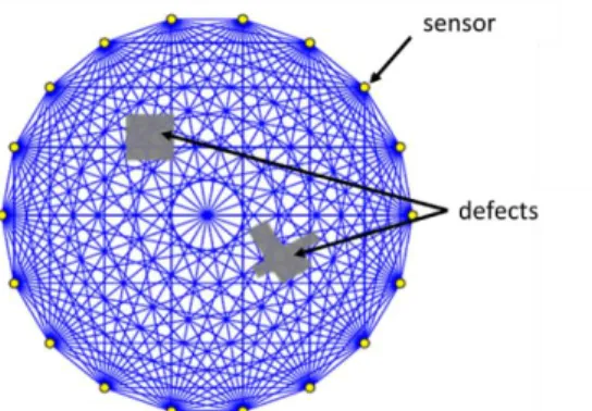
Tomography algorithms aims at reconstructing images of a zone of the structure surrounded by a distribution of sensors. We will consider here only the case of a circular and uniform distribution on a plate (Figure 1).
Figure 1. Circular distribution of sensors around a critical zone and straight-ray assumption for tomography imaging.
The simpler tomography algorithms are based on a straight-ray propagation assumption and requires the determination of the time of flight between all the couples of the sensor’s distribution around the monitored area. This has already been used by Hinders and McKeon [3] to image corrosion, but with a scanning system, not using embedded sensors.
Different algorithms based on this straight-ray propagation hypothesis are listed in [4]:
1. Algebraic Reconstuction Technique (ART)
2. Simultaneous Iterative Reconstructive Technique (SIRT). 3. Simultaneous Algebraic Reconstuction Technique (SART).
SART is the algorithm that better takes into account, under the straight-ray assumption, the physical phenomenon involved in tomography [5].
As soon as spatial extension of defects is large enough to significantly modify the time of flight of rays propagating across it (which is generally the case for configurations of interest in SHM), or if the velocity field in the structure is not uniform, it is however necessary to take into account refraction phenomenon. Straight-ray hypothesis does not represent in that case the real trajectory of wave packet, which leads to (de-)focalization of defect, distorting the dimension and thickness estimations.
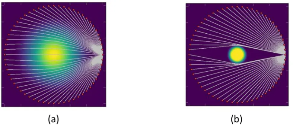
In this paper we present results based on bent-ray algorithm (or Fast Marching Method - Simultaneous Algebraic Reconstuction Technique (FMM-SART) which has been developed to take into account refraction effects (Figure 2 (a)) [6].
(a) (b)
Figure 2. (a) Curvature of rays caused by refraction within a large defect. (b) When the defect is too sharp, ray assumption for wave propagation is not valid, diffraction effects must be taken into account to
correctly image defect.
When thickness variations of the structure are too sharp, the wave nature of the guided elastic waves must be taken into account in order to correctly represent diffraction effects (Figure 2 (b)). Different diffraction tomography algorithms, that take the full signal between two sensors and not only time of flight as input data, have been studied in literature [7,8].
We present in this paper results of an hybrid algorithm, called HARBUT [9], which is a derivation of diffraction tomography based on a first guess obtained from a bent-ray image estimation in an iterative process.
An important parameter for diffraction tomography algorithms is the Born approximation: the phase difference between the incident field and the wave propagating through the unknown object must be less than π [10]. In practice, severe defects (objects of high contrast and extent) can violate this approximation leading to incorrect reconstruction. Thanks to the use of a first guess, HARBUT reduces the residual contrast that should be imaged by diffraction tomography. Two strategies can then be derived for corrosion monitoring depending on the estimated corrosion rate. If bent-ray image is always sufficient to respect Born approximation, the inspection interval is only fixed by the requirement on corrosion monitoring in order to ensure critical defect detection. In cases where Born approximation might be not respected, it is prudent to store the image obtained in the latest state and use it at first guess. In that case the inspection interval might be fixed by the respect of Born approximation for the residual contrast between the two states.
FINITE ELEMENT SIMULATIONS
The range of validity the imaging algorithms presented in the previous part (SART, FMM-SART and HARBUT) are explored using simulations performed with a spectral finite element formulation offered within CIVA simulation platform developed at CEA [11].
Simulation offers the advantage to easily test different configurations (number of sensors, extension and thickness of defect, …) and to visualize the different steps of the algorithms (Figure 3).
Figure 3. Rays and isochrones (lines of equal times of flight) visualization.
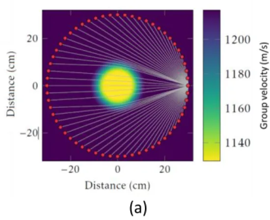
An example of configuration simulated consisted in a 2mm thick aluminium plate (VL = 6360 m/s, VT = 3140 m/s and = 2,7 kg/m3) with 120 sensors placed on a 60 cm
diameter circle. The defect consisted in a circular 0.3 mm thickness reduction on a 12 cm radius placed at the center of the plate. A0 mode at 20 kHz is used to image the
defect.
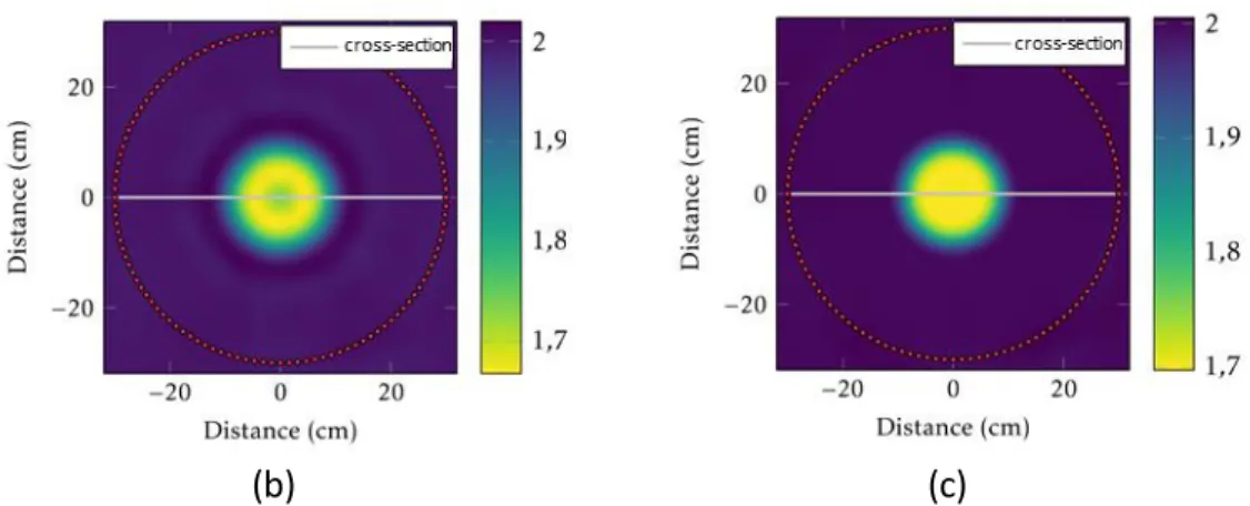
Figure 4 presents tomographic reconstruction using FMM-SART and HARBUT algorithms. Central cross-sections (Figure 5) shows that HARBUT reconstruction is almost perfect whereas FMM-SART reconstruction presents some oscillations in the proximity of the defect due to diffraction effects not taken into account by this algorithm.
(b) (c)
Figure 4. (a) Defect is represented by a loss of thickness or group velocity reduction for A0 mode at 20
kHz on a 2 mm thick aluminium plate. Not all the sensors are represented on this figure for clarity. Defect reconstruction using (b) FMM-SART algorithm and (c) HARBUT using 120 sensors.
Figure 5. Cross-sections of Figure 4.
EXPERIMENTAL RESULTS
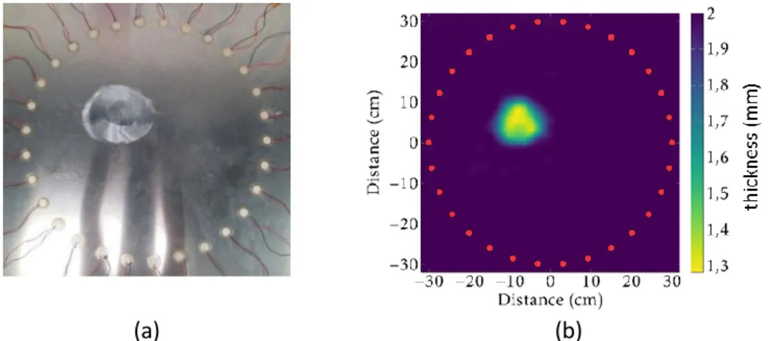
An experimental demonstration of practical interest for SHM has been performed using 30 piezoelectric transducers of 18 mm diameter glued on the 2 mm thick aluminum plate ( 18 mm). A defect has been machined manually with a sander machine with dimensions approximately 14 cm diameter and 0.65 mm thickness reduction. An ultrasonic Cscan has been used to precisely quantify the defect (Figure 6). The emission consisted in a 5 cycles Han modulated toneburst (Figure 7).
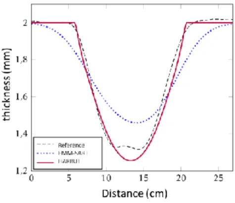
The reconstructions using FMM-SART and HARBUT algorithms are presented on Figure 8. A cross section on the defect confirms quantitatively the better performances of HARBUT algorithm in such configuration.
(a) (b)
Figure 6. (a) Experimental configuration and (b) ultrasonic Cscan measurement of the plate.
Figure 7. Example of experimental signals.
(a) (b)
Figure 9. Cross sections of Figure 8.
CONCLUSION
The major interest of elastic guided waves tomography algorithms for extended corrosion monitoring is their capabilities to give extremely precise information about defect (size and thickness) without baseline signals. They make therefore a very robust solution for SHM.
A large number of tomography algorithms have been presented in literature, initially coming from medical, geophysical or X-ray communities, implying various hypothesis on wave propagation and interaction with defect (ray propagation assumption or not, Born approximation, …). We show here, using both simulation and experiments, that the recently developed HARBUT algorithm gives very promising results in a configuration of practical interest for SHM.
Future studies will aim at testing the performances of this algorithm on other configurations with several defects, more complex structures and combined with passive measurements [12].
REFERENCES
1. Croxford, A.J., P.D.Wilcox, B.W. Drinkwater, G. Konstantinidis 2007. “Strategies for guided-wave structural health monitoring”. Proc. R. Soc. A, 463, 2961–2981.
2. Croxford, A., J., Moll, P. Wilcox, J.E. Michaels. 2010. “Efficient temperature compensation strategies for guided wave structural health monitoring.” Ultrasonics, 50(4), 517-528.
3. Hinders, M. K., J. C. McKeon. 1999. “Lamb wave tomography for corrosion mapping,” Second Joint
NASA/FAA/DoD Conf. Proc. on Aging Aircraft
4. Kak, A., M. Slaney. 1988. “Principles of Computerized Tomographic Imaging.” IEEE Press. 5. Andersen, A.; Kak, A. 1984. “Simultaneous Algebraic Reconstruction Technique (SART): A
Superior Implementation of ART”. Ultrasonic Imaging, 6, 81–94.
6. Li, Shengying et al. 2010. “Refraction corrected transmission ultrasound computed tomography for application in breast imaging”. Medical Physics, 37, 2233–2246.
7. Wang, C.H., L.R. Rose. 2003. “Plate-wave diffraction tomography for structural health monitoring.”
Review of Quantitative Nondestructive Evaluation, 22, 1615–1622.
8. Simonetti, F., N. Huang. 2008. “From beamforming to diffraction tomography”. Applied Physics, 103, 103–110.
9. Huthwaite, P. & F. Simonetti 2011. “High-resolution imaging without iteration: a fast and robust method for breast ultrasound tomography”. Journal of the Acoustical Society of America, 130, 1721– 1734.
10. Belanger, P., P. Cawley, F. Simonetti. 2010. “Guided Wave Diffraction Tomography Within the Born Approximation”, IEEE Transactions on Ultrasonics, Ferroelectrics, and Frequency Control, 57.6, 1405–1418.
11. Imperiale, A., S. Chatillon, P. Calmon, N. Leymarie, S. Imperiale, E. Demaldent. 2016. “UT Simulation of Embedded Parametric Defects Using a Hybrid Model Based Upon Spectral Finite Element and Domain Decomposition Methods”, Proc. of the 19th World Conference on
Non-Destructive Testing, Munich.
12. Druet, T., B. Chapuis, E. Moulin. 2016. “Passive guided wave tomography for corrosion detection”,