HAL Id: hal-02359308
https://hal.archives-ouvertes.fr/hal-02359308
Submitted on 16 Nov 2019HAL is a multi-disciplinary open access archive for the deposit and dissemination of sci-entific research documents, whether they are pub-lished or not. The documents may come from teaching and research institutions in France or abroad, or from public or private research centers.
L’archive ouverte pluridisciplinaire HAL, est destinée au dépôt et à la diffusion de documents scientifiques de niveau recherche, publiés ou non, émanant des établissements d’enseignement et de recherche français ou étrangers, des laboratoires publics ou privés.
(PAMPS–PAAM) substrates
Tadashi Kajiya, Adrian Daerr, Tetsuharu Narita, Laurent Royon, François
Lequeux, Laurent Limat
To cite this version:
Tadashi Kajiya, Adrian Daerr, Tetsuharu Narita, Laurent Royon, François Lequeux, et al.. Dynamics of the contact line in wetting and diffusing processes of water droplets on hydrogel (PAMPS–PAAM) substrates. Soft Matter, Royal Society of Chemistry, 2011, 7 (24), pp.11425. �10.1039/c1sm05944k�. �hal-02359308�
Dynamics of the Contact Line in Wetting and Diffusing Processes
of Water Droplets on Hydrogel (PAMPS-PAAM) Substrates
Journal: Soft Matter
Manuscript ID: SM-ART-05-2011-005944.R1 Article Type: Paper
Date Submitted by the Author: n/a
Complete List of Authors: Kajiya, Tadashi; Université Paris Diderot, Laboratoire Matière et Systèmes Complexes
Daerr, Adrian; Université Paris Diderot, Laboratoire Matière et Systèmes Complexes
Narita, Tetsuharu; ESPCI Paris-tech, Laboratoire Physico-chimie des Polymères et Milieux Dispersés
Royon, Laurent; Université Paris Diderot, Laboratoire Matière et Systèmes Complexes
Lequeux, Francois; ESPCI Paris-tech, Laboratoire Physico-chimie des Polymères et Milieux Dispersés
Limat, Laurent; Université Paris Diderot, Laboratoire Matière et Systèmes Complexes
Note: The following files were submitted by the author for peer review, but cannot be converted to PDF. You must view these files (e.g. movies) online.
manuscriptrev.tex figures.zip publishlicence.zip
Dynamics of the Contact Line in Wetting and Diffusing Processes
of Water Droplets on Hydrogel (PAMPS-PAAM) Substrates
Tadashi Kajiya(a), Adrian Daerr(a), Tetsuharu Narita(b), Laurent Royon(a), Fran¸cois Lequeux(b) and Laurent Limat(a)
(a) Laboratoire MSC, UMR 7057, CNRS, Universit´e Paris Diderot, Bˆatiment Condorcet,
10 rue Alice Domon et L´eonie Duquet, 75205 Paris Cedex 13, France (b) PPMD-SIMM, UMR 7615, CNRS, UPMC, ESPCIParisTech,
10 rue Vauquelin, 75231 Paris Cedex 05, France
(Dated: August 12, 2011)
Abstract
We studied the dynamics of the wetting and diffusing processes of water droplets on hydrogel (Poly (2-acrylamido-2-methyl-propane-sulfonic acid -co- acrylamide)(PAMPS-PAAM)) substrates. The profiles of the droplet and substrate were measured simultaneously using a grid projection method. We observed that as the water droplet diffuses into the gel, the contact line of the droplet exhibits successively two different behaviors: pinned and receding, and the transition between these two behaviors is closely related to the local deformation of the gel substrate. The contact line is pinned at an early stage. As the water diffusion proceeds, the contact angle of the droplet decreases while the angle of the local slope of the gel surface near the contact line increases. At the moment where these two angles almost correspond to each other, the contact line starts to recede. Our results indicate that due to the water diffusion, a locally swollen region is formed in the vicinity of the droplet-gel interface, and whether the contact line is pinned or recedes is determined by the surface property of this swollen region.
I. INTRODUCTION
Gels are materials which have been attracting continued interest as they are an intriguing state of matter in physical and chemical sciences [1] and they also have promising techno-logical potentials in many application fields such as the food processing, drug delivery [2], and cell transplantation [3]. The understanding and control of interfacial properties of gels is of crucial importance in applications: they determine adhesion and friction [4, 5] (e.g. cartilage replacement), surface tension [6] and wetting properties (e.g. soft coatings), opti-cal properties [7] (e.g. anticondensation coatings), effects on bacterial motility [8], etc. Of those problems about the interfacial properties of gels, here we are focusing on the problem of wetting.
Compared to general solid materials on which wetting problems have been extensively studied [9–11], gels have two specific features which can affect the behavior of the contact line, i.e., gels are very soft and swell drastically with liquid. Considering these two aspects, the behavior of the contact line of liquid on gel surfaces might be understood in analogy with the wetting problems on soft and deformable surfaces like elastomers [12–17], or the wetting problems on permeable surfaces like porous media or polymer films [18, 19]. Although the effect of the softness and the liquid permeability were studied separately, the behavior of the contact line on gel surfaces would be yet different from those cases because these two aspects exist simultaneously. Several studies have been conducted to characterize the wetting properties on gel surfaces [20–22], but these studies did not make clear how the behavior of the contact line is different when it is coupled with the local deformation of the substrate and the diffusion of the liquid.
In this article, we studied the wetting and diffusing processes of water droplets on hydro-gel (Poly (2-acrylamido-2-methyl-propane-sulfonic acid -co- acrylamide)(PAMPS-PAAM)) substrates. The precise analysis of the contact line behavior in the presence of the substrate deformation and liquid diffusion requires to measure both the profiles of the droplet and of gel substrate simultaneously. In a static case, the simultaneous measurement of the profiles of the droplet and of substrate was conducted by a fluorescent microscopy for liquid droplets on elastomer surfaces [23–25]. To obtain these two profiles dynamically, we used the “grid projection method”, i.e., we projected a grid pattern below the gel surface and measured its optical distortion induced by the light refraction at the surface to reconstruct the original
profile.
The use of a grid pattern for measuring the profile of a liquid surface has been proposed by Kurata et al. [26] and Fermigier et al. [27] in the problems of free surface flows, and by Andrieu et al. [28] in the dewetting problem of thin liquid films. Recently, Banaha et al. reported that the same technique can be applied to measure the spreading process of liquid on Agar gels [29], in which they measured both the surface profiles of the liquid and of gel. Here we have improved the method of Banaha et al. by extending the optical setup so that a reduced mirror image of the grid pattern is projected inside the gel and is used for the profile measurement. This allows for considerably a high spatial resolution.
We observed that as the water droplet diffuses into the gel substrate, the behavior of the contact line exhibits successively two different regimes: pinned and receding, and the transition between these two regimes is closely related to the local deformation of the sub-strate around the contact line. We discuss how the pinned-receding transition depends on the properties of the gel, i.e., the rigidity and hydrophilicity (tuned by the concentrations of crosslinking agent and of hydrophilic AMPS monomer), which determine the gel swelling ability. In chapter IV, we propose possible mechanisms for the behavior of the contact line.
II. EXPERIMENTAL SECTION
A. Materials
Poly (2-acrylamido-2-methyl-propane-sulfonic acid -co- acrylamide) (PAMPS-PAAM) gels were used for gel substrates and distilled water (Milli-Q Integral; Millipore, USA) was used for liquid droplets. The PAMPS-PAAM gels were prepared through the rad-ical polymerization of a solution of 2-acrylamido-2-methyl-propane-sulfonic acid (AMPS; Sigma-Aldrich, USA) and acrylamide (AAM; Alfa Aesar, USA) in water with a cross-linking agent, N, N′-methylenebisacrylamide (MBA; Sigma-Aldrich, USA), and initiators, Potassium persulfate (PS; Sigma-Aldrich, USA) and N, N, N′, N′-Tetramethylenediamine (TEMED; Sigma-Aldrich, USA). The total molar concentration of monomer was fixed at 1 M. The concentrations of AMPS and of crosslinking agent MBA with respect to the total amount of monomer were tuned as control parameters: CAM P S was set at 10 mol% and 30
mol%, and CM BA was changed from 1 mol% to 20 mol%. Note that CM BA changes the
rigidity of the gel, while CAM P S corresponds the fraction of hydrophilic monomers and thus changes the hydrophilicity of the gel. The concentrations of initiators PS and TEMED were fixed at 1 mol%.
To obtain a sheet-shaped gel substrate with a smooth surface, the gel was prepared between two parallel glass slides which were separated by a silicone rubber spacer with a thickness of 4.5 mm, which always remains large compared to the radius (< 1.5 mm) and height (< 0.45 mm) of the droplet. Before being used, glass slides were pre-cleaned with a 1 M solution of sodium hydrate in ethanol for 1 week. The polymerization was started by heating a monomer solution to 60 ◦C in a heat chamber. For the polymerization to finish completely, the solution was kept in a heat chamber for 2 hours then at room temperature for more than 3 days before it was used for the measurement. The surface roughness of the gel is not known but should not exceed that of the glass surface, i.e., a few tenth of nanometers.
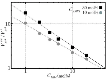
To check the swelling ability of the gel, the volume change of the gel was measured between at the initial state and at the fully swollen state. Here, the fully swollen gel was prepared by dipping the gel in a water bath for more than 1 week. Figure 1 shows the plots of the volume swelling ratio, i.e., the relative volume of the gel at the fully swollen state Vgelsw to at the initial state Vi
gel, against the MBA concentration CM BA in two different AMPS concentrations CAM P S. It is seen that the gel swells drastically with water, and that both the parameters CAM P S and CM BA affect the swelling ability of the gel. For high CAM P S and low CM BA, the gels are swollen up to more than 10 times their initial volumes, while for low
CAM P S and high CM BA, the gels are swollen only to less than twice the initial volumes.
The elasticity of the gel was measured by an indentation tester (TA.XTPlus; Texture Technologies, USA) with a spherical probe (ϕ = 0.5 inch) and was plotted in fig. 2. The refractive index of the gels were measured by a refractometer (ARAGO∞; Cordouan Tech-nologies, France) as 1.350± 0.003 for the gels CAM P S = 30 mol% and 1.346 ± 0.003 for
CAM P S= 10 mol%, which are considerably close to the value of water: 1.331.
B. Setup for Profile Measurement
Figure 3 (a) shows the setups for the profile measurement. A gel substrate was placed on a hollow stage, and a droplet was placed on the substrate with a micropipet. The initial
volume of the droplet Vi
drop was fixed at 1 µl. As the gel is initially under the swelling equilibrium, the droplet of 1 µl completely diffuses into the gel. To restrain the effect of water evaporation from the droplet and from the gel, the droplet and gel substrate were sealed by a small plastic box in which air was saturated with water vapor. This has been performed by depositing a ring of water all around the gel (Note that the water ring does not touch the gel).
To measure both the profile of the droplet and gel simultaneously, a grid projection method was used. In the grid projection method, the profile of the object is obtained by tracing a optical distortion of grid lines. The original grid plate (Array of black lines printed on a transparency. The distance of each line was 400 µm.) was located far from the observation system. The illumination light was emitted from the photodiode (Lumileds; Philips, Netherlands) and passed through the grid plate. After being converted to a parallel light by an optical lens (f = 200 mm), the light was guided toward the bottom of the substrate, and passed through a focus lens (TV lens f = 35 mm; Pentax, Japan). This focus lens projects the mirror image of the grid inside the gel substrate, whose position was set just below the droplet. In all measurements, the depth of the mirror image from the
gel surface was fixed at e0 = 1.875 mm. The grid image was measured by a CCD camera
(A101FC; Basler AG, Germany) with a magnification lens (TV lens f = 25 mm; Pentax, Japan) placed above the droplet.
Figure 3 (b) shows the image of the grid lines obtained after the droplet is placed on a gel substrate. In the mirror image, the distance of each grid line was 59.5 µm, thus the resolution increases up to 6 times of the original grid lines. For analysis, one cross section of the droplet which is perpendicular to the grid lines (indicated in fig. 3 (b) as a dashed line) was used.
III. EXPERIMENTAL RESULTS
A. Shift of Grid Lines and Reconstruction of Profile
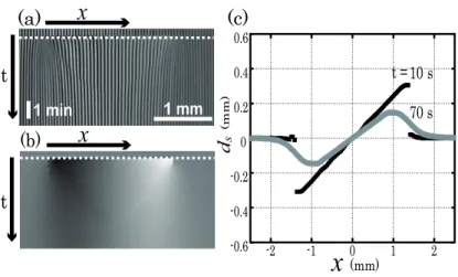
Figure 4 (a) shows the spatio-temporal diagram of grid lines in one cross section of the droplet. It is seen that after the droplet is placed on a substrate, the grid lines in the region of the droplet appears shifted from their initial positions by certain distances. In the left
side of the droplet, the lines shift to left, while the lines shift to right in the right side. Using an image analysis, the positions of all lines (center of black lines and white lines) were detected and were tracked over time, yielding the distance of shift ds with respect to the unperturbed grid. Figure 4 (b) shows the spatio-temporal diagram of the shift distance of grid lines ds(x, t) and fig. 4 (c) shows the plot of ds at two different times. Note that in both figures, the data of ds between the positions of grid lines was linearly interpolated.
Just after the droplet is placed on a substrate (t = 10 s), a large discontinuity of ds exists between the region where the droplet was placed and the outer region, i.e., dsvaries sharply at the edge of the droplet. As the water diffuses from the droplet to the gel (t = 70 s), ds becomes smaller in the droplet region, while the region that ds has a non-zero value extends outwards from the initial position of the edge of the droplet.
As is shown in fig. 5 (a), the shift of grid lines is due to the refraction of lights at the interface between the mediums of different refractive indexes (medium A: air, medium B: water or gel). With geometrical optics, the value of the shift distance ds(x, t) is related to the local slope of the interface tan α(x, t) by the following three equations:
sin α = n sin β, (1)
δ = α− β, (2)
tan δ = ds
e , (3)
where α and β are the angles of the light path in mediums A and B with respect to the normal to the interface, δ is the angle of the light path in medium B with respect to the vertical axis z, n is the refractive index of medium B (since n of the PAMPS-PAAM gel is sufficiently close to the value of water, we used the value of water n = 1.33 for both droplet and gel regions), and e(x, t) is the depth of the grid lines from the interface. At a point
x = x0 located sufficiently far from the droplet, we can consider that α0 = 0 and that e(x0) still remains the initial value e0 before the droplet is placed. From there, α(x) and e(x) are calculated numerically by integrating eqs. (1)-(3) and the relation
e(x) = e0+ ∫ x
x0
dx,tan α(x,), (4)
at each data point. Figure 5 (b) shows the profiles h(x) = e(x)− e0 of the droplet and substrate reconstructed from the data in fig. 4 (c). Here, the calculation was conducted from left x < 0 to right x > 0.
B. Relation between Behavior of Contact Line and Deformation of Substrate
Figure 6 (a) shows the half cross sections of the profiles (the height h against the radial position r) of the droplet and gel substrate at different times (Substrate: CM BA = 5 mol% and CAM P S = 30 mol% ). During the diffusion process of the droplet into the gel substrate, both the profiles of the droplet and substrate change. At an early stage (t = 25 s), the contact line of the droplet is seen clearly, i.e., the slope of the profile is discontinuous at the droplet perimeter. As the water diffusion proceeds, the height of the droplet decreases, while the height of the gel substrate around the contact line increases. The horizontal extent of the substrate deformation grows close to the order of 1 mm from the initial position of the contact line, and the boundary between the droplet and substrate becomes less clear.
Although the contact line is difficult to observe directly at the late stage, it is still possible to detect the position of the contact line using the local curvature of the profile at the center (r ≈ 0). When a water droplet still resides on the gel substrate, the surface of the central region where the droplet resides must be a spherical cap of uniform curvature due to the effect of the surface tension. Therefore, if the local curvature at the center Hc is calculated as: 1 Hc ≈ ∂2h ∂r2 r≈0, (5)
and then it is extrapolated outward, the position of the contact line can be detected as the point where the actual profile deviates from the extrapolated Hc curve. The extrapolated
Hc curves are also plotted in fig. 6 (a) as dashed lines. To show the position of the contact line more clearly, h is replotted as a function of r2 in fig. 6 (b).
Now that the position of the contact line has been detected, it is possible to measure the radius of the droplet R, the effective contact angle of the droplet θdrop with respect to horizontal, and the angle of the local slope of the gel surface θgel close to the contact line. Figure 6 (c) illustrates the determination of R, θdrop and θgel. The angle θdrop was calculated from the radius of the droplet R and the curvature Hc as:
θdrop = sin−1(R/Hc), (6)
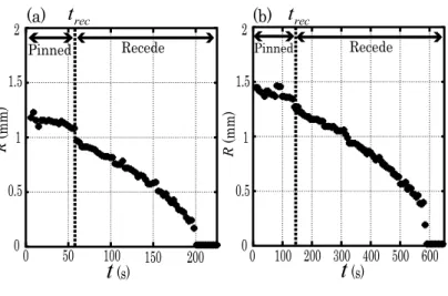
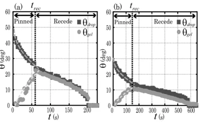
while θgel was directly measured from the slope of the profile in the vicinity of the contact line (The position used for measuring θgel was 1.5 grid spacings (≈ 90 µm) apart from the position of the contact line.). Figure 7 shows the plot of R against the time t, and fig. 8
shows the plot of θdrop and θgel against t. In both figures, data of two different substrates are shown: (a) CAM P S = 30 mol% and CM BA = 5 mol%, (b) CAM P S = 10 mol% and CM BA = 5 mol%.
In fig. 7, although the time scales are different on these two substrates, the general trends are almost the same: the behavior of the contact line exhibits two different regimes. The contact line is initially pinned, i.e., it does not move during a certain period. At a time
t = trec, the contact line starts to recede and then it continues to recede until the droplet has totally diffused into the gel. By comparing fig. 7 to fig. 8, it is clearly observed that the transition of the pinning to receding regimes of the contact line is closely related to the time evolutions of θdrop and θgel. At the initial stage where the contact line is pinned, the values of θdrop and θgel are largely different. As the water diffusion proceeds, these two angles come close to each other: θdrop decreases while θgel increases. At the moment where θdrop and
θgel almost correspond, the contact line starts to recede. This result indicates that at the moment of the contact line recession, the actual contact angle of the droplet with respect to the substrate ∆θ = θdrop− θgel is nearly 0◦. The same trend was observed for all AMPS and MBA concentrations in our experiment.
C. Dependence on Properties of Gel Substrate
In this section, we show how the behavior of the contact line depends on the following parameters: the MBA concentration CM BA that determines the rigidity of the gel substrate and the PAMPS concentration CAM P S that determines the hydrophilicity of the substrate.
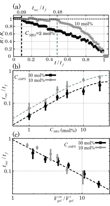
Figure 9 (a) shows the plot of the radii of droplets R against the time t on the substrates
of two different CM BA (2 mol% and 10 mol%), where CAM P S is fixed at 10 mol%. For
the sake of comparison, the radius R and time t are normalized respectively by the initial radius Ri and total diffusion time tf defined as the time at which the droplet has completely diffused into the gel. Figure 9 (a) shows that the relative length of the initial pinned regime to the total diffusion time trec/tf depends upon CM BA of the substrate. For low CM BA (2 mol%) where the rigidity of the substrate is weak, the initial pinned regime is considerably short relative to the total diffusion time (trec/tf = 0.09). The contact line starts to recede immediately after the droplet is placed on the substrate. On the other hand, for high CM BA (10 mol%) where the substrate is more rigid, the initial pinned regime becomes relatively
long, i.e., the contact line is pinned almost the half period of the whole diffusion process (trec/tf = 0.48).
To evaluate the parameter dependence in detail, the relative length of the initial pinned regime to the total diffusion time trec/tf was measured on gels of various CM BA and CAM P S, and was plotted in fig 9 (b). For both CAM P S, trec/tf becomes longer with the increase of
CM BA, i.e., the contact line is pinned for a longer time with the increase of the gel rigidity. Comparing the data of different CAM P S, it is observed in a whole range of CM BAthat trec/tf is shorter for higher CAM P S (30 mol%), i.e., the contact line starts to recede earlier when the gel substrate has higher hydrophilicity.
In fig. 1, it was seen that both the parameters CM BA and CAM P S largely affect the swelling ability of the gel, i.e., the volume swelling ratio Vsw
gel/Vgeli . Considering that, the data trec/tf for all gels are replotted as a function of Vgelsw/V
i
gel in fig. 9 (c). It is clearly observed that trec/tf has an universal negative dependence upon Vgelsw/Vgeli .
IV. DISCUSSION
A. Mechanism of Contact Line Recession with a Nearly Zero Contact Angle:
Formation of a Locally Swollen Region
In this section, we discuss why the actual contact angle of the droplet ∆θ = θdrop −
θgel becomes nearly 0◦ at the moment of the contact line recession. Figure 10 shows the schematics of the physical model we propose.
After the droplet is placed on a gel substrate, the water starts to diffuse from the droplet into the substrate (here we assume that the effect of the evaporation is considerably smaller than of the diffusion into the substrate.), and the gel substrate deforms as it swells with water. From the fact that the horizontal size of the deformation of the substrate xd is of the order of 100 µm to 1 mm and it grows as a function of time, we consider that the dominant factor for the deformation is the effect of the swelling (Another possible factor which causes the deformation of the substrate is the balance between the capillary force and elastic force [12, 14]. However, the characteristic size of xdin that case is considerably smaller: xd ≈ γ/E is of the order of 1 µm for E = 25 kPa [14, 24].).
Here we consider the diffusion of water into the gel with an analogy of the drying problems
of the droplet [30, 31]. Due to the geometry of the droplet, it is expected that the diffusive flux of water near the edge of the droplet is strongly enhanced compared to the center (fig. 10 (a)). Therefore, the substrate in the vicinity of the contact line swells with water quite rapidly, and it forms a “locally swollen” region. Once it is formed, the contact line feels the surface of this locally swollen region, and whether the contact line can recede or not is determined by the wetting property of the swollen gel surface. (fig. 10 (b)).
To check the wetting property of the swollen gel surface, we conducted a supplemental wetting experiment on a gel substrate which is previously fully swollen in a water bath. To avoid that a thin water layer could remain on the gel surface, the level of the water bath is always kept below the gel surface during the swelling process, and the gel surface was softly wiped with an optical cleaning tissue (Kimwipes; Kimberly-Clark Professional, USA) before being used. We observed that on a fully swollen gel substrate, the droplet spreads rapidly and the contact angle takes a considerably small value (< 3◦) irrespective of the MBA concentration and AMPS concentration. (This result can be understood in terms of the thermodynamic equilibrium. Since the fully swollen gel is equilibrated with the bulk water, putting a water droplet on the fully swollen gel is thermodynamically nearly the same condition as putting a water droplet on a bulk water, where the droplet spreads completely.) From the results of the supplemental experiment, it is expected that the equilibrium contact angle on the locally swollen gel surface is very close to 0◦. For the contact to recede on a gel substrate, the actual contact angle of the droplet with respect to the slope of the substrate ∆θ = θdrop− θgel must correspond to the equilibrium contact angle on a swollen gel surface. Therefore, the contact line is pinned until ∆θ reaches nearly 0◦.
The negative dependence of trec/tf on the volume swelling ratio of the substrate Vgelsw/Vgeli in fig. 9 (c) can be understood in terms of the growth of the deformation of the gel surface. For the gel substrate with a large swelling ratio, after a droplet is placed on the substrate, the region near the water-gel interface changes its volume drastically by swelling with water, which causes the large rise of the gel surface around the droplet. Therefore, the angle of the local slope of the gel surface at the contact line θgel increases rapidly up to the value of
θdrop at an early stage of the diffusion process. On the other hand, for the substrate with a small swelling ratio, the rise of the gel surface due to the swelling effect is relatively small. In that case, θdrop does not corresponds to θgel until the droplet diffuses most of water into the gel and decreases θdrop to considerably a small value.
B. Analysis for Characteristic Time of Contact Line Recession
In this section, we propose a modeling for estimating the time of the contact line recession. Here we consider a simple model depicted in fig. 11 to get the order of magnitude for the behaviors of θdrop and θgel at the initial pinned-contact line stage.
We assume that below the droplet, the water diffusion creates the diffusive boundary layer of typical thickness √Dt, where D is the diffusion coefficient of water in the gel. The
typical volume flux of water at the water-gel interface z = zgel is scaled as
J ∼ Dϕsw√− ϕi
Dt . (7)
where ϕsw is the volume fraction of water in the fully swollen gel (suppose that at the water-gel interface, water-gel is immediately swollen), and ϕi is the volume fraction of water in the gel at the initial state. Due to this flux, the volume of the droplet dVdrop ≈ πR3θdrop decreases as dVdrop dt ≈ πR 3dθdrop dt =−πR 2J. (8)
while the volume of the gel increases as
dVgel dt ≈ πR 2dzgel dt = πR 2 J. (9)
The local slope of the gel near the contact line θgel is estimated to be close to the ratio
zgel/dgel, where zgel designates the vertical displacement of the droplet basis due to swelling, and dgel, the horizontal distance on which this displacement relaxes radially around the droplet. With an analogy of a contact problem of solid bodies [32], here we assume that the shape of the gel surface is mainly dictated by a compromise between the shear elasticity of the gel and the rising condition z = zgel at the droplet basis of radius R. The characteristic size of dgel is thus estimated as the same order of the droplet radius: dgel ∼ R. (Rigorously, the water diffusion in a horizontal direction affects the shape of the gel surface in addition to the deformation due to the rise of the droplet basis. However, at an early stage where the characteristic size of the swollen region in a horizontal direction xgel ≈ zgel ∼ (ϕsw− ϕi)
√ Dt
is sufficiently smaller than the size of the droplet R, this effect can be neglected.)
Combining eqs. (7) - (9), the time evolution of the angles θdrop and θgel are obtained as
θdrop(t)− θ (0) drop∼ − ϕsw− ϕi R √ Dt. (10) 11
θgel(t)∼
ϕsw− ϕi
R √
Dt. (11)
where θdrop(0) is the initial value of the effective contact angle of the droplet. Equations (10) and (11) predict that the time evolutions of θdrop(t)− θ(0)drop and of θgel(t) are proportional to
√
t. In fig. 8, the fitting curves (a + b√t with fitting parameters a and b) are drawn for θdrop and θgel as dashed lines. Except for the data of θgel at a very early stage in fig. 8 (a) (where the experimental uncertainty is not negligible), the experimental data fits the curves well.
From eqs. (10) and (11), the characteristic time of the contact line recession τ , i.e., the time when the actual contact angle ∆θ = θdrop− θgel goes to zero, is thus estimated as
τ ∼ (Rθ
(0) drop)2
D(ϕsw − ϕi)2
. (12)
Let us calculate τ for our gel (CM BA = 5 mol%, CAM P S = 10 mol%): R = 1.42 mm,
θdrop(0) = 27.1◦, and ϕsw − ϕi = 0.0529 (obtained by the data of swelling ratio). For the diffusion coefficient D, we refer to the data in ref. [33]: the value which is closest to our
system is AAm/AMPS in water (AMPS/mg = 300) in tab. 5: D = 39.47× 10⁻⁸ m2/s. By
substituting these values in eq. (12), τ is calculated as ca. 400 s. Experimentally, the time for the onset of the contact line recession was measured as 140 s, which is not far from our theoretical estimation.
V. CONCLUSION
In this article, we have studied the dynamics of the wetting and diffusing processes of water droplets on hydrogel (Poly (2-acrylamido-2-methyl-propane-sulfonic acid -co-acrylamide)(PAMPS-PAAM)) substrates. The profiles of the droplet and substrate were measured dynamically using a grid projection method. We have observed that as the water droplet diffuses into the gel, the behavior of the contact line successively exhibits two differ-ent regimes: pinned and receding, and the transition between these two regimes is closely related to the local deformation of the gel substrate. The contact line is initially pinned after the droplet is placed. As the water diffusion proceeds, the effective contact angle of the droplet decreases while the angle of the local slope of the gel surface near the contact line increases. Finally these two angles almost correspond to each other, and it is at this moment that the contact line starts to recede. This result indicates that at the moment
of the contact line recession, the actual contact angle is nearly 0◦. We have also discussed how the pinned-receding transition depends on the properties of the gel substrate such as the rigidity and hydrophilicity, and have found that the length of the initial pinned regime largely depends on the gel swelling ability.
About the mechanism of the pinning-receding transitions of the contact line, we have proposed a physical model that a locally swollen region is formed in the vicinity of the contact line, and that whether the contact line is pinned or recede is determined by the wetting property of this swollen region. This model correctly reproduces the evolutions of the droplet and gel angles at the initial pinned-contact line stage, and explains the effect of the gel swelling ability on the length of the initial pinned regime.
Our results show that the dynamics of the contact line on hydrogel substrates are quite different from those observed for general solid materials, especially for the coupling between the pinning-receding transition of the contact line and the angles of the droplet and substrate. Further studies are required for the detailed analysis of the present phenomena, especially for the late stage of the diffusion process where the contact line recedes and the swollen region grows up to the size of the droplet. This would be possible by solving the combined equations of the water transport from the droplet to gel and of the balance of interfacial tensions at the contact line, which will be expected in future works.
Acknowledgement
The authors gratefully thank Y. Shimokawa, K. Sakai and M. Doi (Tokyo University) for discussions about the theoretical and experimental parts of this work.
[1] M. Doi, J. Phys. Soc. Jpn., 2009, 78, 052001:1-19.
[2] N.A. Peppas, P. Bures, W. Leobandung and H. Ichikawa, Eur. J. Pharm. Biopharm., 2000, 50, 27-46.
[3] J. Yang, M. Yamato, C. Kohno, A. Nishimoto, H. Sekine, F. Fukai and T. Okano, Biomaterials, 2005, 26, 6415-6422.
[4] J. P. Gong, T. Kurokawa, T. Narita, G. Kagata, Y. Osada, G. Nishimura and M. Kinjo, J. Am. Chem. Soc., 2001, 123, 5582-5583.
[5] G. Kagata, J. P. Gong and Y. Osada, J. Phys. Chem. B, 2002, 106, 4596-4601. [6] H. Kikuchi, K. Sakai and K. Takagi, Jpn. J. Appl. Phys., 1991, 30, L:1668-1670. [7] G. Wang, D. Chen, L. Lu, X. Wang and Y. Yang, J. Coat. Tech., 1998, 70, 55-59.
[8] D. Julkowska, M. Obuchowski, I. B. Holland and S. J. S´eror, Microbiology, 2004, 150, 1839-1849.
[9] P. G. de Gennes, F. B. Wyart and D. Quere, Capillarity and Wetting Phenomena, Springer, 2003.
[10] P. G. de Gennes, Rev. Mod. Phys. 1985, 57, 827-863.
[11] D. Bonn, J. Eggers, J. Indekeu, J. Meunier and E. Rolley, Rev. Mod. Phys. 2009, 81, 739-805. [12] M. E. R. Shanahan and P. G. de Gennes, C. R. Acad. Sci. Paris, 1986, 302, Ser. II, 517. [13] M. E. R. Shanahan, J. Phys. D: Appl. Phys., 1987, 20, 945-950.
[14] C. W. Extrand and Y. Kumagai, J. Colloid Interface Sci., 1996, 184, 191-200. [15] A. Carr´e and M. E. R. Shanahan, Langmuir, 1995, 11, 24-26.
[16] A. Carr´e, J. C. Gastel and M.E.R. Shanahan, Nature, 1996, 379, 432-434. [17] A. Carr´e and M. E. R. Shanahan, Langmuir, 2001, 17, 2982-2985.
[18] L. Bacri and F. B. Wyart, Eur. Phys. J. E: Soft Matter Biol. Phys, 2000, 3, 87-97.
[19] A. Tay, C. Monteux, D. Bendejacq and F. Lequeux, Eur. Phys. J. E: Soft Matter Biol. Phys, 2010, 33, 203-210.
[20] D. Szab´o, S. Akiyoshi, T. Matsunaga, J. P. Gong and Y. Osada, J. Chem. Phys., 2000, 113, 8253-8259.
[21] D. Kaneko, J. P. Gong, M. Zr´ınyi and Y. Osada, J. Polym. Sci., Part B: Polym. Phys., 2005, 43, 562-572.
[22] Y. Nonomura, Y. Morita, T. Hikima, E. Seto, S. Chida and H. Mayama, Langmuir, 2010, 26, 16150-16154.
[23] R. P. C´amara, A. Best, H. J. Butt and E. Bonaccurso, Langmuir, 2008, 24, 10565-10568. [24] R. P. C´amara, G. K. Auernhammer, K. Koynov, S. Lorenzoni, R. Raiteri and E. Bonaccurso,
Soft Matter, 2009, 5, 3611-3617.
[25] E. R. Jerison, Y. Xu, L. A. Wilen and E. R. Dufresne, Phys. Rev. Lett., 2011, 106, 186103:1-4. [26] J. Kurata, K. T. V. Grattan, H. Uchiyama and T. Tanaka, Rev. Sci. Instrum., 1990, 61,
736-739.
[27] M. Fermigier, L. Limat, J. E. Wesfreid, P. Boudinet and C. Quilliet, J. Fluid. Mech., 1992, 236, 349-383.
[28] C. Andrieu, D. Chatenay and C. Sykes, C. R. Acad. Sci. Paris, 1995, 320, 351-357. [29] M. Banaha, A. Daerr and L. Limat, Eur. Phys. J. Special Topics, 2009, 166, 185-188. [30] R. D. Deegan, O. Bakajin, T. F. Dupont, G. Huber, S. R. Nagel and T. A. Witten, Phys. Rev.
E: Stat., Nonlinear, Soft Matter Phys., 2000, 62, 756-765.
[31] H. Hu and R. G. Larson, J. Phys. Chem. B, 2002, 106, 1334-1344.
[32] L. D. Landau and E. M. Lifshitz, Theory of Elasticity, Butterworth Heinemann, 3rd edn., 1986.
[33] S. Kundakci, ¨O. B. ¨Uz¨um and E. Karadaˇg, Reac. Func. Polym., 2008, 68, 458-473.
1 10 1 10 i gel sw gel V V / (mol%) MBA C 30 mol% AMPS C 10 mol%
FIG. 1: Plot of the volume swelling ratio: relative volume of the gel at the fully swollen state to the initial state Vsw
gel/Vgeli , against the MBA concentration. The data of two different AMPS
Initial state Fully swollen state
(a) 1 10 (mol%) MBA C 0 50 100 150 200 250 300 350 400 450 (kPa) E 0 50 100 150 200 250 300 350 400 450 (kPa) E 1 10 (mol%) MBA C (b) Initial state Fully swollen state
FIG. 2: Plot of the elasticity of the gel against the MBA concentration. The AMPS concentrations were 30 mol% for (a) and 10 mol% for (b). In each figure, data of gels at the initial states (before swelling) and at the fully swollen states are plotted with different symbols.
1 mm
Mirror image of grid
Diffuser Illumination Grid Converting lens (f = 200mm) Focus lens (f = 35mm) 200mm (a) (b) Plastic box Water ring C C D C C D
FIG. 3: (a) Schematic of the setup for the profile measurement. Using two lenses (converting lens: f = 200 mm, focus lens: f = 35 mm), the mirror image of the grid was projected inside the gel which was located just below the droplet. (b) An image of grid lines which is taken after the droplet is placed on the gel substrate. Due to the deformation of the interface (air-water and air-gel), the grid lines are distorted and their apparent spacing has changed.
(a) (b) t t 1 mm 1 min -0.6 -0.4 -0.2 0 0.2 0.4 0.6 -2 -1 0 1 2 (m m ) 10 s 70 s t = (c) (mm)
x
s dx
x
FIG. 4: (a) Spatio-temporal diagram of the grid lines in one cross section of the droplet. (b) Spatio-temporal diagram of the shift distances of lines ds. ds is proportional to a gray-scale: the
dark region means that the grid shifts to left and the bright region indicates the grid shifts to right. In figures (a) and (b), the dashed line indicates the time that droplet is placed. (c) Profiles of the shift distances ds at two different times (10 s, 70 s). The position x = 0 indicates the center of the
droplet and the shift distance becomes positive when the line shifts to right. For all figures, the MBA and AMPS concentrations of the substrate are 5 mol% and 30 mol%, respectively.
0 0.1 0.2 0.3 0.4 0.5 0.6 -2 -1 0 1 2 ( m m ) t = 10 s 70 s 䃐 䃑 䃑
e
(a) (b) (mm)x
h
s d A B Medium x z to CCDδ
FIG. 5: Reconstruction of the profile. (a) Geometry of the light path that passes the grid image and is detected by the CCD. As the interface between two mediums A (air) and B (water or gel) of different refractive indexes is inclined with respect to the horizontal axis x, the light is refracted at the interface. (b) Reconstructed profiles of the droplet obtained from the data in fig. 5 (c). Profiles at two different times (10 s, 70 s) are plotted.
0 0.05 0.1 0.15 0.2 0.25 0.3 0.35 0.4
h
(mm) 2 1.5 1 0.5 0 (mm) Centerr
Edge 0.45 25 s t = 50 s 100 s 150 s 200 s h ( m m) ((mm) ) r2 2 (a) (b)Droplet Gel substrate
Center R drop θ gel θ (c) 0 0.1 0.2 0.3 0.4 0 0.5 1 1.5 2 2.5 50 s 150 s Drop Substrate Drop Substrate Actual Profile ExtrapolatedHCcurve
FIG. 6: (a) Half cross sections of the profiles of the droplet and substrate (CM BA = 5 mol%,
CAM P S= 30 mol%) at 5 different times (25 s, 50 s, 100 s, 150 s, and 200 s). The solid lines indicate
the actual profiles, while the dashed lines indicate the extrapolations of the local curvatures at the center Hc. (b) Replot of the height h against the second power of the radial position r2. The
positions of the contact lines where the actual profiles deviate from the extrapolated Hc curves are
marked as dotted lines. (c) Definition of parameters R, θdrop, and θgel.
0 50 100 150 200 (s)
t
0 0.5 1 1.5 2 R ( mm ) 0 100 200 300 400 500 600 0 0.5 1 1.5 2 (s)t
(a) (b)Pinned Recede Pinned Recede
R ( mm ) rec t rec t
FIG. 7: Plot of the radius of the droplet (the region having a same curvature as the center) R against the time t. The MBA concentration CM BAis fixed at 5 mol%, and the AMPS concentrations
(s) 0 50 100 150 200
t
0 10 20 30 40 50 60 θ (de g) (a)θ
dropθ
gel 0 10 20 30 40 50 60 θ (de g) 0 100 200 300 400 500 600 (s)t
(b)Pinned Recede Pinned Recede
rec
t
t
recθ
dropθ
gelFIG. 8: Plot of the angles of the droplet θdrop and gel substrate θgel with respect to horizontal
against the time t. The MBA concentration CM BAis fixed at 5 mol%, and the AMPS concentrations
CAM P S are (a) 30 mol% and (b) 10 mol%. In the left part of each figure, the fitting curves of the
theoretical model proposed in sec. IV B are marked as gray dashed lines.
(b)
(a)
0 0.2 0.4 0.6 0.8 1 0 0.2 0.4 0.6 0.8 1 ft
t /
iR
R
/
CMBA=2 mol% 10 mol% 0.09t
rec/
t
f 0.48 0.1 1 1 CMBA(mol%) 10 f re ct
t
/
(c)
1 0.1 f re ct
t
/
1 i 10 gel sw gel V V / 30 mol% AMPS C 10 mol% 30 mol% AMPS C 10 mol%FIG. 9: (a) Plot of the normalized radius of the droplet R/Ri against the normalized time t/tf
(CAM P S = 10 mol%). Data of two different MBA concentrations CM BA (2 mol% and 10 mol%)
are plotted. The time when the contact line recession starts trec/tf are marked as dashed lines. (b)
Plot of trec/tf against CM BA. Data of two different CAM P S (10 mol% and 30 mol%) are plotted
(a) (b) Diffusive flux Swollen gel Droplet Contact line ∆θ
FIG. 10: Mechanism of the recession of contact line. (a) The initial stage that the contact line is pinned. For geometrical reasons, diffusive flux from the droplet to the gel is strongly enhanced near the contact line. (b) The second stage where the contact line recedes. Due to the water diffusion, a locally swollen region has formed near the contact line. For the contact line to recede, the actual contact angle ∆θ (the angle with respect to the slope of the substrate) must correspond to the equilibrium contact angle on this swollen gel surface.
z
R
J
θ
drop gelθ
gel Z 0 droplet gel geld
) , (x yr
r
For table of contents: 1 mm t 1 min 1 mm 0 0.05 0.1 0.15 0.2 0.25 0.3 0.35 0.4 h (m m ) 2 1 0.5 0 (mm) Center r Edge 0.45 25 s t = 100 s 200 s
Position of contact line
Profiles of droplet and gel substrate
Extrapolation of curvature
1.5
With our observation technique using a grid projection, we discovered a pinning-depinning transition of the contact line in wetting and diffusing processes of water droplets on hydrogel (PAMPS-PAAM) substrates.
Response Response Response
Response to the comments ofto the comments ofto the comments of refereesto the comments ofrefereesrefereesreferees
Journal: Soft Matter
Manuscript ID: SM-ART-05-2011-005944
Title: "Dynamics of the Contact Line in Wetting and Diffusing Processes of Water droplets on Hydrogel (PAMPS-PAAM) Substrates"
Author(s): Tadashi Kajiya, Adrian Daerr, Tetsuharu Narita, Laurent Royon, Francois Lequeux, Laurent Limat
Referee1 Referee1 Referee1 Referee1 (1) (1) (1)
(1) >>Do the authors know something about the roughness of the dry hydrogel? If yes, I
suggest to add that information.
(Answer) Currently we do not have the exact value of the roughness of the gel substrate. However, in the gel preparation process, we carefully made the gel surface as smooth as possible by preparing it between 2 pre-cleaned glass slides. Under this condition, the roughness of the gel is presumably the same of glass slides, which is typically the order of 10 nm. We have added sentences for mentioning this point in section II-A (line 11, page 4).
(2) (2) (2)
(2) >>Right now I do not have access to refs. 26 and 27. Is the optical shape analysis
described there? If yes, I suggest to describe it here only briefly and remove Figs. 4+5. >>I am not sure if in conclusion the optical analysis of the drop shape should be mentioned. If I understood correctly this was already described in refs. 26+27.
(A) Please note that we cited refs. 26 and 27 for referring the basic theories of geometrical optics about the optical distortion due to the curved surface, and the systems mentioned in these 2 articles are totally different from ours (ref. 26 is about the optical correction for PIV measurement, and ref. 27 is about obtaining the velocity profiles in oscillating Newtonian and Maxwellian fluids).
Considering that refs. 26 and 27 are far from our subject, we have replaced them to the following four articles in which the grid pattern is used for measuring the surface profile of liquid, which is closer to our problem.
[28] C. Andrieu et al. C. R. Acad. Sci. Paris 1995, 320, 351-357. [29] M. Banaha et al. Eur. Phys. J. Special Topics, 2009, 166, 185-188.
([26] and [27] are about the surface flows, [28] is about the dewetting process of the thin liquid film, and [29] is about the spreading process of liquid on Agar gel.)
What we have directly referred for our experiment is the method used in ref. [29]. We have improved the method of Banaha et al. by expanding the optical setup so that the reduced mirror image of the grid is projected inside the gel and used for the measurement, which allows for a considerably high spatial resolution.
To explain about how the grid pattern was applied to the measurement of the liquid surface profile and how the method has been developed, we have added sentences in the “Introduction” part (line 2, page 3). We have also mentioned how we have extended the experimental setup in comparison with the previous works.
In relation to that, we have rewritten the sentence in the “Conclusion” part (line 20, page 12).
(3) (3) (3)
(3) >>I did not understand the sentence around equation (5). I suggest to rewrite it.
(A) We have rewritten the explanations around equation (5) to make the detection method of the contact line clearer to understand (line 11, page 7). In relation to that, we have added words for explanation in fig. 6.
(4) (4) (4)
(4) >>Page 7: I do not really like the sentence “The contact line undergoes two different
states”. What is a state of a line? What the authors refer to is, if I understand correctly, that the change of the contact radius with time shows two regimes.
(A) Based on the referee’s suggestion, we have rewritten the sentence mentioned above to “the behavior of the contact line exhibits successively two different regimes” (line 5, page 8). We have also rewritten the expression “state of the contact line” to “behavior of the contact line” throughout the parts of this manuscript (abstract, introduction, and conclusion, etc.).
(5) (5) (5)
(5) >> In the analysis for the characteristic time of the contact line only diffusion is
diffuse radially. In particular for small drops this may be a strong effect. The authors should integrate or comment on this effect.
(A) We are here not trying to solve the problem in details, but just give an approximate scaling law that represents roughly our data. We agree that there is also the effect of the
water diffusion in radial direction in addition to the scale based on the droplet radius R.
However, since the swollen region grows horizontally and vertically as
Dt z
xgel ≈ gel ~(φsw −φi) ,
the radial size of the swollen region is sufficiently smaller than the size of deformation
due to the rise of the droplet basis (order of R) at an early stage (in our system, it is
typically up to ~100 s). As a first approximation, we thus neglected the effect of the radial diffusion in the calculations of the gel slope. We have added a comment regarding this point in section IV-B (line 22, page 11).
On the other hand, the radial diffusion is of course essential at the later stage of the diffusion process (especially at the second regime where the contact line recedes), and this should be considered in future works. We have added sentences at the last part of “Conclusion” (line 14, page 13).
Referee2 Referee2 Referee2 Referee2 (1) (1) (1)
(1) >>The experimental details on how the evaporation of water from the drop and gel
was prevented during the experiment are not clear for me. The authors described that the gel substrate was surrounded by macroscopic water droplets, which is also unclear for me. Was the experiment performed in a saturated water vapor environment? A detailed illustration of the chamber for gel substrate might be helpful.
(A) We have modified fig. 3 (a) by adding a detailed illustration inside the chamber, which clearly explains how we prevented the water evaporation. In relation to that, we have rewritten the sentences in the body text (line 2, page 5).
(2) (2) (2)
(2) >>Related to the above question, were the gels used in the experiment in equilibrium
force is balanced by the capillary force (the thermodynamic equilibrium). However, the authors claimed that the deformation is due to swelling, not due to the thermodynamic equilibrium.
(A) The substrates used in the wetting experiment are initially below the swelling equilibrium (except for the supplemental experiment for checking the wetting property on a fully-swollen gel explained in section IV-A), and their swelling abilities were checked in section II-A. After we put the gel substrate in the chamber, we placed the droplet and started the measurement immediately. The droplet of 1 μl completely diffuses into the gel.
To avoid the confusion, we have added a sentence in section II-B (line 1, page 5) to clarify that the gel was initially under the swelling equilibrium. We have also rewritten the sentences in section II-A (line 14, page 4) to explain that the swelling ability of the gel was checked in the preparative experiment.
(3) (3) (3)
(3) >>If not, then the pinning time should depend on swelling ratio deviation from the
equilibrium state. In this case, how did the authors control the swelling ratio for different samples?
(A) This point is explained in section III-C (the experimental results about how the pinning time depends on the gel properties) and at the last paragraph in section IV-A (the mechanism). As the referee insists, the duration of pinning clearly depends on the swelling ability of the gel, i.e., how the gel is far from its swelling equilibrium. In this experiment, we controlled 2 properties of the gel: the gel rigidity (tuned by the concentration of cross-linker) and gel hydrophilicity (tuned by the concentration of hydrophilic AMPS monomer). Both parameters affect the swelling ability.
To make it clear which parameter we controlled, we have added a brief explanation in the “Introduction” part (line 13, page 3) and “Conclusion” part (line 1, page 13), and a detailed explanation in the “Experimental Section” part (line 29, page 3).
(4) (4) (4)
(4) >> The description on the relation between the refractive index and the gel
composition was not accurate (l.8, p.4). The refractive index should not only depend on the AMPS concentration but also on the cross-linker concentration, as the latter substantially change the swelling ratio.
(A) The refractive index also varies against the cross-linker concentration, but the change of the value is the order of 0.001, which is relatively small. We have confirmed it by comparing the refractive indexes of gels of different cross-linker concentrations, and also by comparing the refractive indexes between gels and monomer solution (without cross-linker). We have added the variance of refractive index (line 26, page 4).
(5) (5) (5)
(5) >> L.6 from bottom, p.9. The meaning of the description “To prohibit that the water
cover the surface of the gel,” is not clear.
(A) The aim of this process is to completely remove the free water layer from the gel surface. We have rewritten the sentence to make the description clearer (line 8, page 10).
(6) (6) (6)
(6) >> There are many mistakes in English. Some are listed as follows:
l.15, p.2; “porous medias” should be “porous medium” l.23, p.2; “PAAM-PAMPS” should be “PAMPS-PAAM” l.22, p.3; “silicon” should be “silicone”
l.15, p.4: “the gel substrate were….” should be “the gel substrate was….” l.22, p.4; “pass trough” should be “pass through”
l.22, p.4; “the grid plate and was” should be “the grid plate was” l.7, p.12; “PAAM-PAMPS” should be “PAMPS-PAAM”
(A) We have modified the parts as the author suggested, and we have conducted the spelling check in the entire part of the manuscript.
(Note: l.15, p.2; we have rewritten as a plural form “porous media”.
l.22, p.4; we have rewritten the entire part of this sentence to make it clearer to understand (line 11, page 5).)
Dear Editorial Staffs of Soft Matter,
We are submitting a Revised ManuscriptRevised ManuscriptRevised ManuscriptRevised Manuscript (For reference, we also attach a highlighted highlighted highlighted highlighted
ver ver ver
version of the manuscriptsion of the manuscriptsion of the manuscriptsion of the manuscript in which revised parts based on the referees’ comments are
highlighted as yellow bold lines and red rectangles.), and ResponseResponseResponseResponse to the Comments ofto the Comments ofto the Comments ofto the Comments of
R R R
Refereesefereesefereeseferees for publication in Soft MatterSoft MatterSoft Matter. Soft Matter
Manuscript Manuscript Manuscript
Manuscript IDIDID: SM-ART-05-2011-005944 ID
Title Title Title
Title: “Dynamics of the Contact Line in Wetting and Diffusing Processes of Water Droplets on Hydrogel (PAMPS-PAAM) Substrates”
Manuscript Type Manuscript Type Manuscript Type
Manuscript Type: Full paper Au
Au Au
Authorthorthorthorssss: Tadashi Kajiya, Adrian Daerr, Tetsuharu Narita, Laurent Royon,
François Lequeux, Laurent Limat Corresponding Author
Corresponding Author Corresponding Author
Corresponding Author: Tadashi Kajiya
We would be grateful if you could let us know your decision at your earliest convenience. Sincerely yours,
--
Tadashi KAJIYA
JSPS Postdoctral Fellow
Laboratoire MSC, UMR 7057, CNRS, Université Paris Diderot 10 rue Alice Domon et Léonie Duquet, 75205 PARIS, FRANCE Tel: 33 (0)1 57 27 62 79
Dynamics of the Contact Line in Wetting and Diffusing Processes
of Water Droplets on Hydrogel (PAMPS-PAAM) Substrates
Tadashi Kajiya(a), Adrian Daerr(a), Tetsuharu Narita(b), Laurent Royon(a), Fran¸cois Lequeux(b) and Laurent Limat(a)
(a) Laboratoire MSC, UMR 7057, CNRS, Universit´e Paris Diderot, Bˆatiment Condorcet,
10 rue Alice Domon et L´eonie Duquet, 75205 Paris Cedex 13, France (b) PPMD-SIMM, UMR 7615, CNRS, UPMC, ESPCIParisTech,
10 rue Vauquelin, 75231 Paris Cedex 05, France
(Dated: August 12, 2011)
Abstract
We studied the dynamics of the wetting and diffusing processes of water droplets on hydrogel (Poly (2-acrylamido-2-methyl-propane-sulfonic acid -co- acrylamide)(PAMPS-PAAM)) substrates. The profiles of the droplet and substrate were measured simultaneously using a grid projection method. We observed that as the water droplet diffuses into the gel, the contact line of the droplet exhibits successively two different behaviors: pinned and receding, and the transition between these two behaviors is closely related to the local deformation of the gel substrate. The contact line is pinned at an early stage. As the water diffusion proceeds, the contact angle of the droplet decreases while the angle of the local slope of the gel surface near the contact line increases. At the moment where these two angles almost correspond to each other, the contact line starts to recede. Our results indicate that due to the water diffusion, a locally swollen region is formed in the vicinity of the droplet-gel interface, and whether the contact line is pinned or recedes is determined by the surface property of this swollen region.
I. INTRODUCTION
Gels are materials which have been attracting continued interest as they are an intriguing state of matter in physical and chemical sciences [1] and they also have promising techno-logical potentials in many application fields such as the food processing, drug delivery [2], and cell transplantation [3]. The understanding and control of interfacial properties of gels is of crucial importance in applications: they determine adhesion and friction [4, 5] (e.g. cartilage replacement), surface tension [6] and wetting properties (e.g. soft coatings), opti-cal properties [7] (e.g. anticondensation coatings), effects on bacterial motility [8], etc. Of those problems about the interfacial properties of gels, here we are focusing on the problem of wetting.
Compared to general solid materials on which wetting problems have been extensively studied [9–11], gels have two specific features which can affect the behavior of the contact line, i.e., gels are very soft and swell drastically with liquid. Considering these two aspects, the behavior of the contact line of liquid on gel surfaces might be understood in analogy with the wetting problems on soft and deformable surfaces like elastomers [12–17], or the wetting problems on permeable surfaces like porous media or polymer films [18, 19]. Although the effect of the softness and the liquid permeability were studied separately, the behavior of the contact line on gel surfaces would be yet different from those cases because these two aspects exist simultaneously. Several studies have been conducted to characterize the wetting properties on gel surfaces [20–22], but these studies did not make clear how the behavior of the contact line is different when it is coupled with the local deformation of the substrate and the diffusion of the liquid.
In this article, we studied the wetting and diffusing processes of water droplets on hydro-gel (Poly (2-acrylamido-2-methyl-propane-sulfonic acid -co- acrylamide)(PAMPS-PAAM)) substrates. The precise analysis of the contact line behavior in the presence of the substrate deformation and liquid diffusion requires to measure both the profiles of the droplet and of gel substrate simultaneously. In a static case, the simultaneous measurement of the profiles of the droplet and of substrate was conducted by a fluorescent microscopy for liquid droplets on elastomer surfaces [23–25]. To obtain these two profiles dynamically, we used the “grid projection method”, i.e., we projected a grid pattern below the gel surface and measured its optical distortion induced by the light refraction at the surface to reconstruct the original
profile.
The use of a grid pattern for measuring the profile of a liquid surface has been proposed by Kurata et al. [26] and Fermigier et al. [27] in the problems of free surface flows, and by Andrieu et al. [28] in the dewetting problem of thin liquid films. Recently, Banaha et al. reported that the same technique can be applied to measure the spreading process of liquid on Agar gels [29], in which they measured both the surface profiles of the liquid and of gel. Here we have improved the method of Banaha et al. by extending the optical setup so that a reduced mirror image of the grid pattern is projected inside the gel and is used for the profile measurement. This allows for considerably a high spatial resolution.
We observed that as the water droplet diffuses into the gel substrate, the behavior of the contact line exhibits successively two different regimes: pinned and receding, and the transition between these two regimes is closely related to the local deformation of the sub-strate around the contact line. We discuss how the pinned-receding transition depends on the properties of the gel, i.e., the rigidity and hydrophilicity (tuned by the concentrations of crosslinking agent and of hydrophilic AMPS monomer), which determine the gel swelling ability. In chapter IV, we propose possible mechanisms for the behavior of the contact line.
II. EXPERIMENTAL SECTION
A. Materials
Poly (2-acrylamido-2-methyl-propane-sulfonic acid -co- acrylamide) (PAMPS-PAAM) gels were used for gel substrates and distilled water (Milli-Q Integral; Millipore, USA) was used for liquid droplets. The PAMPS-PAAM gels were prepared through the rad-ical polymerization of a solution of 2-acrylamido-2-methyl-propane-sulfonic acid (AMPS; Sigma-Aldrich, USA) and acrylamide (AAM; Alfa Aesar, USA) in water with a cross-linking agent, N, N′-methylenebisacrylamide (MBA; Sigma-Aldrich, USA), and initiators, Potassium persulfate (PS; Sigma-Aldrich, USA) and N, N, N′, N′-Tetramethylenediamine (TEMED; Sigma-Aldrich, USA). The total molar concentration of monomer was fixed at 1 M. The concentrations of AMPS and of crosslinking agent MBA with respect to the total amount of monomer were tuned as control parameters: CAM P S was set at 10 mol% and 30
rigidity of the gel, while CAM P S corresponds the fraction of hydrophilic monomers and thus changes the hydrophilicity of the gel. The concentrations of initiators PS and TEMED were fixed at 1 mol%.
To obtain a sheet-shaped gel substrate with a smooth surface, the gel was prepared between two parallel glass slides which were separated by a silicone rubber spacer with a thickness of 4.5 mm, which always remains large compared to the radius (< 1.5 mm) and height (< 0.45 mm) of the droplet. Before being used, glass slides were pre-cleaned with a 1 M solution of sodium hydrate in ethanol for 1 week. The polymerization was started by heating a monomer solution to 60 ◦C in a heat chamber. For the polymerization to finish completely, the solution was kept in a heat chamber for 2 hours then at room temperature for more than 3 days before it was used for the measurement. The surface roughness of the gel is not known but should not exceed that of the glass surface, i.e., a few tenth of nanometers.
To check the swelling ability of the gel, the volume change of the gel was measured between at the initial state and at the fully swollen state. Here, the fully swollen gel was prepared by dipping the gel in a water bath for more than 1 week. Figure 1 shows the plots of the volume swelling ratio, i.e., the relative volume of the gel at the fully swollen state Vgelsw to at the initial state Vi
gel, against the MBA concentration CM BA in two different AMPS concentrations CAM P S. It is seen that the gel swells drastically with water, and that both the parameters CAM P S and CM BA affect the swelling ability of the gel. For high CAM P S and low CM BA, the gels are swollen up to more than 10 times their initial volumes, while for low
CAM P S and high CM BA, the gels are swollen only to less than twice the initial volumes.
The elasticity of the gel was measured by an indentation tester (TA.XTPlus; Texture Technologies, USA) with a spherical probe (ϕ = 0.5 inch) and was plotted in fig. 2. The refractive index of the gels were measured by a refractometer (ARAGO∞; Cordouan Tech-nologies, France) as 1.350± 0.003 for the gels CAM P S = 30 mol% and 1.346 ± 0.003 for
CAM P S= 10 mol%, which are considerably close to the value of water: 1.331.
B. Setup for Profile Measurement
Figure 3 (a) shows the setups for the profile measurement. A gel substrate was placed on a hollow stage, and a droplet was placed on the substrate with a micropipet. The initial
volume of the droplet Vi
drop was fixed at 1 µl. As the gel is initially under the swelling equilibrium, the droplet of 1 µl completely diffuses into the gel. To restrain the effect of water evaporation from the droplet and from the gel, the droplet and gel substrate were sealed by a small plastic box in which air was saturated with water vapor. This has been performed by depositing a ring of water all around the gel (Note that the water ring does not touch the gel).
To measure both the profile of the droplet and gel simultaneously, a grid projection method was used. In the grid projection method, the profile of the object is obtained by tracing a optical distortion of grid lines. The original grid plate (Array of black lines printed on a transparency. The distance of each line was 400 µm.) was located far from the observation system. The illumination light was emitted from the photodiode (Lumileds; Philips, Netherlands) and passed through the grid plate. After being converted to a parallel light by an optical lens (f = 200 mm), the light was guided toward the bottom of the substrate, and passed through a focus lens (TV lens f = 35 mm; Pentax, Japan). This focus lens projects the mirror image of the grid inside the gel substrate, whose position was set just below the droplet. In all measurements, the depth of the mirror image from the
gel surface was fixed at e0 = 1.875 mm. The grid image was measured by a CCD camera
(A101FC; Basler AG, Germany) with a magnification lens (TV lens f = 25 mm; Pentax, Japan) placed above the droplet.
Figure 3 (b) shows the image of the grid lines obtained after the droplet is placed on a gel substrate. In the mirror image, the distance of each grid line was 59.5 µm, thus the resolution increases up to 6 times of the original grid lines. For analysis, one cross section of the droplet which is perpendicular to the grid lines (indicated in fig. 3 (b) as a dashed line) was used.
III. EXPERIMENTAL RESULTS
A. Shift of Grid Lines and Reconstruction of Profile
Figure 4 (a) shows the spatio-temporal diagram of grid lines in one cross section of the droplet. It is seen that after the droplet is placed on a substrate, the grid lines in the region of the droplet appears shifted from their initial positions by certain distances. In the left
side of the droplet, the lines shift to left, while the lines shift to right in the right side. Using an image analysis, the positions of all lines (center of black lines and white lines) were detected and were tracked over time, yielding the distance of shift ds with respect to the unperturbed grid. Figure 4 (b) shows the spatio-temporal diagram of the shift distance of grid lines ds(x, t) and fig. 4 (c) shows the plot of ds at two different times. Note that in both figures, the data of ds between the positions of grid lines was linearly interpolated.
Just after the droplet is placed on a substrate (t = 10 s), a large discontinuity of ds exists between the region where the droplet was placed and the outer region, i.e., dsvaries sharply at the edge of the droplet. As the water diffuses from the droplet to the gel (t = 70 s), ds becomes smaller in the droplet region, while the region that ds has a non-zero value extends outwards from the initial position of the edge of the droplet.
As is shown in fig. 5 (a), the shift of grid lines is due to the refraction of lights at the interface between the mediums of different refractive indexes (medium A: air, medium B: water or gel). With geometrical optics, the value of the shift distance ds(x, t) is related to the local slope of the interface tan α(x, t) by the following three equations:
sin α = n sin β, (1)
δ = α− β, (2)
tan δ = ds
e , (3)
where α and β are the angles of the light path in mediums A and B with respect to the normal to the interface, δ is the angle of the light path in medium B with respect to the vertical axis z, n is the refractive index of medium B (since n of the PAMPS-PAAM gel is sufficiently close to the value of water, we used the value of water n = 1.33 for both droplet and gel regions), and e(x, t) is the depth of the grid lines from the interface. At a point
x = x0 located sufficiently far from the droplet, we can consider that α0 = 0 and that e(x0) still remains the initial value e0 before the droplet is placed. From there, α(x) and e(x) are calculated numerically by integrating eqs. (1)-(3) and the relation
e(x) = e0+ ∫ x
x0
dx,tan α(x,), (4)
at each data point. Figure 5 (b) shows the profiles h(x) = e(x)− e0 of the droplet and substrate reconstructed from the data in fig. 4 (c). Here, the calculation was conducted from left x < 0 to right x > 0.