HAL Id: hal-02626289
https://hal.uca.fr/hal-02626289
Submitted on 26 May 2020
HAL is a multi-disciplinary open access
archive for the deposit and dissemination of
sci-entific research documents, whether they are
pub-lished or not. The documents may come from
teaching and research institutions in France or
abroad, or from public or private research centers.
L’archive ouverte pluridisciplinaire HAL, est
destinée au dépôt et à la diffusion de documents
scientifiques de niveau recherche, publiés ou non,
émanant des établissements d’enseignement et de
recherche français ou étrangers, des laboratoires
publics ou privés.
Interference Study of Coexisting IEEE 802.11 and
802.15.4 Networks
Ali Mamadou Mamadou, Joël Toussaint, Gerard Chalhoub
To cite this version:
Ali Mamadou Mamadou, Joël Toussaint, Gerard Chalhoub. Interference Study of Coexisting IEEE
802.11 and 802.15.4 Networks. 8th IFIP/IEEE International Conference on Performance Evaluation
and Modeling in Wired and Wireless Networks, Nov 2019, Paris, France. �hal-02626289�
Interference Study of Coexisting IEEE 802.11 and
802.15.4 Networks
Ali Mamadou Mamadou
University of Clermont Auvergne ali.mamadou mamadou@uca.fr
Joel Toussaint
University of Clermont Auvergne joel.toussaint@uca.fr
Gerard Chalhoub
University of Clermont Auvergne gerard.chalhoub@uca.fr
Abstract—Several access technologies are expected to coexist and share the same spectrum portion for next-generation net-works. However, to date, few tools exist in the literature when it comes to evaluating protocol performance in scenarios implying the coexistence of heterogeneous access technologies. We report herein, an extension of an open-source simulation framework for OMNeT++ (INET) to simulate interference impact on the coexistence of IEEE 802.11 and IEEE 802.15.4 in the 2.4GHz ISM bands. We extended the interference module of INET to take into account inter-technology and inter-channel interferences.
Index Terms—network simulation, coexistence, cross technol-ogy interference, IEEE 802.11, IEEE 802.15.4.
I. INTRODUCTION
Access technologies are widely deployed for next-generation networks. Several of these access technologies are expected to coexist and share the same spectrum portion. This calls for solutions to mitigate interference issues for high-density deployment.
In the literature interference and coexistence issues, in general, have been widely studied both on analytical and practical approaches for example for access technologies based on IEEE standards [1], [2]. Simulation-based approaches are often preferred because of the difficulty of implementing large-scale tests. In the literature there are several simulation tools for evaluating wireless access protocols in general. However, to date, few can simulate interference effect in scenarios of coexistence of heterogeneous technologies.
We propose in this paper an extension to the INET frame-work to consider interference effect in simulating heteroge-neous networks. INET is an open-source network simulation module for OMNet++ with protocol models of wired and wireless networks [11]. The proposed model is based on the overlap factor of radio channels. Such a model has been used in [3] to illustrate efficiency of a channel assignment algorithm in a network based on IEEE 802.11 standard. We illustrate our implementation with simulation campaign of scenarios involving coexistence of IEEE 802.11 and IEEE 802.15.4 protocol models in the 2.4GHz band. As we will present related works in section II, this is a first attempt to simulate coexistence of these access technologies with the consideration of interference effect. The remainder of the paper is organized as follows. In Section III, we present the simulation model. In section IV we present and discuss results of simulation. And finally, in section V we conclude and give some perspectives of this work.
II. RELATED WORK
With commodity devices, authors in [2] quantified degra-dation of performance when an IEEE 802.15.4 based network (Zigbee) coexists with an 802.11 (Wi-Fi) network in the IEEE 2.4GHz band and gave some deployment guidelines to avoid this. In [4], authors quantified through practical measurements the LoRa resilience to interference from an IEEE 802.15.4 network on the 868MHz unlicensed band. Authors in [5] investigate the impact of interference of technologies in ISM bands in general on the LoRa modulation depending on a Signal-to-Interference radio (SIR). The model is based on a simulation model that defines the SIR ratio in accordance with the bandwidth of the interfering signal, where interfering signals are assumed to have a common modulation technique. Authors in [6] report a simulation framework to evaluate fair coexistence of Wi-Fi and LTE in the 5GHz based on 3GPP recommendations. The framework uses Wi-Fi and LTE models in the NS-3 open source network simulator. Project in [7] intends to provide a simulation framework for coexistence evaluation of access technologies based on 3GPP standards. The framework relies on the coexistence stack in NS-3 which globally aims to provide general-purpose simulation models of radio channel and physical layer that are technology inde-pendent.
None of the existing works deal with Wi-Fi and ZigBee interference in the INET simulation platform. This platform is designed to emulate multiple access technologies in the same simulation scenarios. We chose to include a more realistic interference model in INET in order to obtain more realistic behavior when simulating different technologies using the same frequency band. Currently, it only takes into consider-ation interference for the same technology when using the same modulation and the same communication channel. This approach can be applied to any other wireless network simu-lator. In what follows, we propose an extension to the existing model to deal with inter-channel interference (interference between different IEEE 802.11 channels) and inter-technology interference (interference between IEEE 802.11 and IEEE 802.15.4) in the 2.4GHz frequency band.
III. THE SIMULATION MODEL
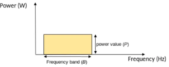
In our simulation framework, transmission of a radio inter-face using an access technology is characterized as a signal having a power (P ) and a frequency band of the transmitting
interface (B). In order to simplify the implementation of our model, we assume that the power value does not change in the frequency domain as illustrated in Figure 11.
Fig. 1. Representation of energy of transmission of a radio interface where the signal is assumed to have constant power spectral density.
In the existing implemented model of INET, when a trans-mission T r is received on a radio interface: a signal-to-noise-plus-interference ratio (SNIR) is calculated and compared to a predefined threshold to decide on reception success. This SNIR is computed for n interfering transmissions IT r according to equations (1) and (2). SN IR = α ∗ P (T r) I + N (1) where: I = n X i=1 αi∗ P (IT ri) ∗ λi (2)
α, αi: are the relative path loss coefficients of T r and IT ri
respectively (between [0, 1]);
N : is a constant value of background noise. λi=
0, if B(IT ri) does not overlap with B(T r).
1, if B(IT ri) totally overlaps with B(T r) and
B(T r) and B(IT ri) have common center frequency.
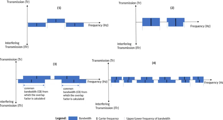
Figure 2 (1) and (2) illustrates the scenarios where λiwould
be 0 or 1 respectively.
With binary λi values, the model does not simulate the
case where B(T ri) partially overlaps with B(T r) and center frequencies are not necessarily common. As shown in Figure 3, this may occur given the number of channels that can be used in 802.11, and between 802.11 and 802.15.4 in the 2.4 GHz band. For instance this can happen in the following cases: (1) if T r is from an 802.11 interface on channel 1, and T riis
from an 802.11 interface also but on channel 2, or 3. Or (2) if T r is from an 802.15.4 interface on a channel between 11 and 14, and T ri is from an 802.11 interface using channel 1.
We extended λito λ0ito handle other cases of partial overlap
between B(IT ri) and B(T r). In scenarios such as those
shown in Figure 2 (3), we allow λi to have values between [0,
1] proportionally to common bandwidth (CB) between T r and IT ri. We call this proportion the overlap factor. For partial
overlaps shown in Figure 2 (4), we considered λi to be 1.
Thus, the new λi in eq. (2) is:
1In reality, energy of a radio signal is the highest at the center frequency
and gets lower on the edge of the transmission channel depending on the spreading factor and modulation technique.
λ0i=
0, if B(IT ri) does not overlap with B(T r).
1, if B(IT ri) totally overlaps with B(T r). CB(T r,IT ri)
B(T r) , otherwise.
IV. EXPERIMENTATION AND RESULTS
This section presents results of our series of simulations. We start with tests that show the model of intra-technology and intra-channel interference implemented in our simulation framework in subsection IV-A where λiis not extended. Then,
based on these test results, we present in subsections IV-B and IV-C, scenarios and results highlighting the extension of λi to
λ0iin eq. (2). All scenarios in this section last 120 seconds per simulation run. Note that the aim of these simulation scenarios is to show the impact of taking into account inter-channel and inter-technology interference. We are not interested in quantitative results. Hence, the number of iterations and the adopted scenarios are only a means to validate the simulation model and show the impact of this type of interference. A. Intra-technology and intra-channel interference
1) 802.11 network scenario: we considered an 802.11 network in infrastructure mode where we gradually add trans-mitter nodes that send the same amount of traffic (1400 Bytes every 100 milliseconds) to a Sink node in order to maximize the average traffic of the Sink at a certain number of nodes in the network.
Figure 4 shows that, the maximum average throughput at the Sink is reached when there are near 75 transmitter nodes in the network. It is to be noted that this is related to the access mechanism employed in IEEE 802.11 and consistent with previous analytical estimations [9] [10].
2) 802.15.4 network scenario: we considered here nodes that transmit traffic (88 Bytes every 200 milliseconds) to a Sink node in ad-hoc mode using a model of 802.15.4 access protocol, where transmitter nodes are gradually added to the network.
Figure 5 shows that it is from about fifty transmitters in the network that the maximum average application throughput of the Sink node is reached. This is also related to the access mechanism employed in IEEE 802.15.4 and consistent with existing evaluations [8].
B. Intra-technology and inter-channel interference
We considered for this scenario two co-located 802.11 networks both in infrastructure mode. We kept the same configuration as the one defined in Section IV-A1, and 76 transmitter nodes have been deployed in each network. We assume this number of transmitters is the one that maximizes network traffic in the scenario defined in Section IV-A1. Then, the channel of one of the networks (WLAN 1) is set to 1 and that of the other (WLAN 2) is varied from 1 to 13.
Figure 6 shows that:
• if WLAN 2 is on channels between 6 and 13 (channels that does not overlap with fixed channel 1 of WLAN
Fig. 2. Scenarios of channel overlapping of transmission with respect to another interfering transmission.
Fig. 3. IEEE 802.11 and IEEE 802.15.4 channels in the 2.4GHz band.
Fig. 4. Average application throughput at Sink depending on the number of nodes in the network (1 run).
1), we find the same amount of traffic received at both network Sinks. This traffic volume is the same as that of the experience in IV-A1 for the same number (76) of
Fig. 5. Average application throughput at the 802.15.4 sink node depending on the number of nodes in network (1 run).
nodes in the network.
Fig. 6. Average application throughput at sinks depending on the operating channel of the coexisting WLAN (5 runs).
overlap with fixed channel 1 of WLAN 1) the traffic of both networks is disrupted. Note that interference between channels 1 and 5 is the least significant because the overlap factor is the smallest.
It can also be noted that when both 802.11 networks are all on channel 1, we obtain results equivalent to the previous scenario (Fig. 4) for 130 nodes if we add the 2 networks.
C. Inter-technology interferences
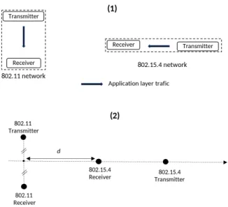
For these experiments, we co-located an 802.15.4 network and an 802.11 network. With a node pair in each network, where transmitter nodes send periodic traffic to receiver nodes. The network topology is illustrated in figure 7 (1) . Traffic of transmitter of the 802.15.4 network is fixed to 88 Bytes every 200 milliseconds. For the transmitter in the 802.11 network, the packet size of the traffic is also fixed to 1400 Bytes, but the generation period depends on the scenarios of the following paragraphs.
Fig. 7. Network topology for the experience of inter-technology interferences simulation.
1) Impact of 802.11 traffic on 802.15.4 traffic: In this experiment, we wanted to know at which period of packet generation in the 802.11 network, the traffic in the 802.15.4 network will cease to be disrupted. The 802.11 network is on
channel 1 and 802.15.4 network is on channel 12 (a scenario of overlapping channels).
This experiment shows that using CSMA/CA for both tech-nologies allows networks to co-exist given a certain offered load that does not overload the channel.
For this experiment and the following ones, the relative position and the transmit power of the nodes of both networks was first determined in such a way that at 1 ms of packet generation period in the 802.11 networks the traffic of the 802.15.4 network link is totally disrupted.
Fig. 8. Traffic disruption in 802.15.4 network depending on traffic generation period in the 802.11 network (5 runs).
Figure 8 shows that periods up to 4 ms there is almost a total traffic disruption on the 802.15.4 link. From the period of 5 to 7 ms the disturbance decreases proportionally as the period increases. For periods greater than 8 ms there is almost no traffic disruption on the 802.15.4 link.
2) Impact of operating channel in 802.11 network on the traffic in 802.15.4 network: For this experiment, the 802.11 network channel was set to 6. The channel of the 802.15.4 network is varied from 11 to 26. Application traffic on the 802.11 link is set to 1 packet every 5 ms, a period during which, traffic on the 802.15.4 link is disrupted as shown in figure 8.
Fig. 9. Total number of packets received at the 802.15.4 receiver depending on the operating channel of the coexisting 802.11 network (5 runs).
Figure 9 shows the impact of overlapping channels of the two networks on the 802.15.4 link:
• If the channels of the two networks not overlap, we notice 600 packets received at the 802.15.4 receiver which corresponds to the number of packets transmitted.
• Traffic disruption in 802.15.4 is only occurring if the
channels of the two networks overlap, and we notice the same disturbance compared to the previous scenario (Fig. 8) for the same period of 5 ms.
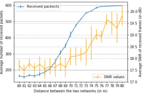
3) Impact of distance and 802.11 traffic on 802.15.4 link: For this experience, we kept the same configuration as the previous scenario except we fixed the channel of the 802.15.4 network to 17. We varied the distance d shown in the figure 7 (2) between the two networks. This distance is defined by the distance between a point midway between the 802.11 trans-mitter and receiver and the position of the receiver 802.15.4. While this distance varies on the axis shown in figure 7 (2), the relative position of the 802.15.4 transmitter is fixed with respect to the 802.15.4 receiver, as well as that of the 802.11 transmitter with respect to the 802.11 receiver. 20 m is the value of this distance in previous scenarios.
Fig. 10. 802.15.4 receiver: average application packets received and average SNIR of received frames when the distance between the two networks is increased up to 80m (5 runs).
Figure 10 shows that the average number of application packet received at 802.15.4 receiver increases proportionally with the increase in the distance between the two networks. We notice also that the link quality of the 802.15.4 receiver (in terms of average SNIR of received frames) increases with the growth of distances between the two networks.
V. CONCLUSIONANDPERSPECTIVES
Wireless access technologies are the building block of to-days new technologies including IoT and 5G networks. Many access technologies are expected to co-exist in the same phys-ical space. This co-existence has an impact on performance caused by interference when access technologies operate on overlapping channels. Most existing simulation tools fail to emulate interference between different technologies, making the evaluation of different networks unrealistic without taking into account the impact of this interference.
We simulated coexistence of heterogeneous access tech-nologies with the consideration of interference effect between them in a more realistic framework for coexistence evaluation. This new model would allow researchers to evaluate proposals dealing with the deployment of IEEE 802.15.4 and IEEE 802.11 networks in the same interfering area.
For future work, this framework could be further enhanced in order to take into consideration the fact that the energy level of a radio signal may vary over the frequency domain depending on the modulation technique used. We believe that this model will help achieve more realistic performance esti-mation through simulation for co-existing wireless networks.
REFERENCES
[1] Yang, Dong, Youzhi Xu, and Mikael Gidlund. ”Wireless coexistence between IEEE 802.11-and IEEE 802.15. 4-based networks: A sur-vey.” International Journal of Distributed Sensor Networks 7.1 (2011): 912152.
[2] Chalhoub, Gerard, Eric Perrier de La Bathie, and Michel Misson. ”Overhead caused by wifi on zigbee networks using slotted CSMA/CA.” (2016).
[3] Arunesh Mishra, Vivek Shrivastava, Suman Banerjee, and William Arbaugh. 2006. Partially overlapped channels not considered harmful. In Proceedings of the joint international conference on Measurement and modeling of computer systems (SIGMETRICS ’06/Performance ’06). ACM, New York, NY, USA, 63-74. DOI=http://dx.doi.org/10.1145/1140277.1140286
[4] Orfanidis, Charalampos, et al. ”Investigating interference between LoRa and IEEE 802.15. 4g networks.” 2017 IEEE 13th International Confer-ence on Wireless and Mobile Computing, Networking and Communica-tions (WiMob). IEEE, 2017.
[5] Elshabrawy, Tallal, and Joerg Robert. ”The Impact of ISM Interference on LoRa BER Performance.” 2018 IEEE Global Conference on Internet of Things (GCIoT). IEEE, 2018.
[6] Mehrnoush, Morteza, et al. ”Modeling, Simulation and Fairness Anal-ysis of Wi-Fi and Unlicensed LTE Coexistence.” arXiv preprint arXiv:1805.03011 (2018).
[7] Peter D. Barnes, Jr., Matthew D. Bielejeski, David. R. Jefferson, Steven G. Smith, David G. Wright, Lorenza Giupponi, Katerina Kout-lia, and Colby Harper. 2019. S3: the Spectrum Sharing Simulator. In Proceedings of the 2019 Workshop on Next-Generation Wireless with ns-3 (WNGW 2019). ACM, New York, NY, USA, 34-37. DOI: https://doi.org/10.1145/3337941.3337945
[8] Longlong, Shi, et al. ”The Research and Simulation of CSMA/CA Mechanism of ZigBee Protocol.” Procedia Engineering 29 (2012): 3466-3471.
[9] Ho, Tien-Shin, and Kwang-Cheng Chen. ”Performance analysis of IEEE 802.11 CSMA/CA medium access control protocol.” Proceedings of PIMRC’96-7th International Symposium on Personal, Indoor, and Mobile Communications. Vol. 2. IEEE, 1996.
[10] Bianchi, Giuseppe. ”Performance analysis of the IEEE 802.11 dis-tributed coordination function.” IEEE Journal on selected areas in communications 18.3 (2000): 535-547.