HAL Id: hal-02022665
https://hal.archives-ouvertes.fr/hal-02022665
Submitted on 18 Feb 2019
HAL is a multi-disciplinary open access
archive for the deposit and dissemination of
sci-entific research documents, whether they are
pub-lished or not. The documents may come from
teaching and research institutions in France or
abroad, or from public or private research centers.
L’archive ouverte pluridisciplinaire HAL, est
destinée au dépôt et à la diffusion de documents
scientifiques de niveau recherche, publiés ou non,
émanant des établissements d’enseignement et de
recherche français ou étrangers, des laboratoires
publics ou privés.
Using a Token Approach for the MAC layer of Linear
Sensor Networks: Impact of the node position on the
Packet Delivery
El Hadji Malick Ndoye, Frédérique Jacquet, Michel Misson, Ibrahima Niang
To cite this version:
El Hadji Malick Ndoye, Frédérique Jacquet, Michel Misson, Ibrahima Niang. Using a Token Approach
for the MAC layer of Linear Sensor Networks: Impact of the node position on the Packet Delivery.
Wireless days, Nov 2014, Rio de Janeiro, Brazil. �hal-02022665�
Using a Token Approach for the MAC layer of
Linear Sensor Networks:
Impact of the node position on the Packet Delivery
El Hadji Malick Ndoye
∗,†, Fr´ed´erique Jacquet
∗, Michel Misson
∗and Ibrahima Niang
†∗ Clermont Universit´e / LIMOS CNRS - Complexe scientifique des C´ezeaux, 63172 Aubi`ere cedex, France
Emails : {ndoye,jacquet,misson}@sancy.univ-bpclermont.fr
†Laboratoire d’Informatique, Universit´e Cheikh Anta Diop de Dakar (UCAD), B.P. 5005 Dakar-Fann, S´en´egal
Email : [email protected]
Abstract—Wireless sensor networks (WSNs) consist of a large number of sensor nodes which communicate via wireless links for monitoring applications. In several applications, such as the monitoring of pipelines or roads, the network topology is linear. This type of WSN is called linear sensor network (LSN). Our goal is to improve the behavior of a MAC protocol for LSNs, by using a token approach. As usual, the possession of the token grants the node permission to transmit on the medium during a given amount of time. The payload of the token is used to propagate network parameters such as delay between tokens, sleep and wakeup calendar. In this paper, we study the behavior of this MAC protocol and we evaluate the impact of the node position on the packet delivery for two types of LSNs.
Keywords—Wireless sensor network, linear topology, MAC pro-tocol, token approach, packet delivery
I. INTRODUCTION
Wireless sensor networks (WSNs) consist of a large num-ber of small sensors for monitoring applications. In some applications, sensors are deployed in a linear manner. For example, sensors can detect the presence of workers in a gallery of an underground mine [1], or of fluid leaks in water or oil pipelines [2]. Sensors can also transmit data between the wagons of a freight train [3][4]. In this paper, we focus on this kind of wireless sensor networks and we refer to them as Linear Sensor Networks (LSNs). MAC protocols designed for wireless sensor networks, usually classified into contention-based protocols and time division multiple access protocols, are not often suitable for LSN due respectively to collisions occurring during contention periods and to strict synchronization constraints. Our protocol is based on a slotted access method needing a soft synchronization in a LSN. It uses a periodic token which allows a node to send data traffic toward the sink (called uplink traffic) or from the sink toward the nodes (called downlink traffic). This paper is dealing with the impact of the node position on the delivery ratio at the sink when the traffic reaches saturation conditions.
This paper is organized as follows: Section II presents the state of the art. Section III describes network topologies and hypotheses for this evaluation. Section IV presents our token based MAC protocol. Section V evaluates two types of LSN in terms of packet delivery ratio. Finally, we conclude our paper in Section VI.
II. STATE OF THE ART
Many token based MAC protocols are designed for wireless networks in order to enhance throughput, delivery ratio, end-to-end delay and/or energy saving[5] [6]. In recent years, authors focus on token based MAC protocols designed specifically for wireless sensor networks. In [7], authors present a Hybrid MAC with a Token Approach (HMAC-TA); the token approach is used to avoid constraints of a strict synchronization and the hybrid approach is used to improve network performance with a combination of the strength of CSMA and TDMA protocols. The Token Bus Based MAC protocol (TBB-MAC) proposed in [8] aims to reduce energy waste by minimizing the amount of redundant communications and to improve end-to-end delay in a clustered WSN. ToKeN-TWiNs (TKN-TWN) described in [9] is a data gathering protocol; it exploits the advantages of TDMA and eases the scheduling burden by using two tokens to arbitrate transmission activities. This proposition was designed for WSNs deployed according to a tree topology and it loses some appeal for a linear topology. Token based MAC protocols are also used in underwater acoustic sensor networks to improve performances [10][6]. These protocols deals mainly with the token passing management according a token ring approach but are not relevant for a LSN.
Even if the token based protocols presented above improve performance of classic or clustered WSNs, they are not de-signed for LSN and do not take advantage of the specificities of such a topology. The design of a MAC protocol for a LSN must consider a trade-off between the specificities of this kind of networks: topology, low density, small processing power, energy limitations, etc. We propose a MAC protocol based on a slotted access method needing a soft synchronization and taking advantage of the linearity of node deployment.
III. HYPOTHESES AND NETWORK TOPOLOGY
A. Hypotheses
In this paper, the nodes are supposed to be uniformly dis-tributed on a line in a rather static way. Packets are forwarded from node to node without aggregation in a store-and-forward manner. Address management and routing protocol are treated as in [11]. Any node that has the token can transmit data frames. These frames could be forwarded one or several nodes away depending on the network redundancy. Nevertheless it is
important to keep the possibility to route packets from the sink to one or several nodes of the LSN.
B. Network topology
In a LSN, it is possible to identify at least three types of nodes [12]: (i) the Sink is a specific node at one extremity of the network that gathers all the traffic transmitted on the network (in the following, we consider without loss of generality that the sink is at the right end of the LSN), (ii) the Allocator is a specific node at the other extremity having neighbors only on one side (we consider that the allocator is at the left end), (iii) between the two previous nodes, basic nodes (called Current Nodes) are distributed along a line. Both the radio range of each node and the distance between nodes have a strong impact on the connectivity of a LSN. In the following, the nodes are supposed to be uniformly distributed on a line between the Allocator and the Sink. Let us consider a LSN with N nodes and one sink: the allocator called Node 1 is the nearest neighbor of Node 2 and the nearest node of the sink is Node N.
Let d be the distance between two adjacent nodes and r the radio range. If d < r < 2d, each current node has only two neighbors (one at the left and one at the right) as shown on Fig. 1a. This topology is called strictly linear. The network is not redundant and is exposed to the effect of node and link failures. If r > 2d, the network is redundant ie each node has several neighbors in each direction. Thus, several possibilities exist for traffic forwarding along the path. If 2d < r < 3d, each current node has exactly two left and two right neighbors as shown on Fig. 1b. In the following, we focus on this kind of redundant LSNs, and we refer to them as 2-Redundant LSNs.
Fig. 1b: Nodes of a 2−Redundant LSN Fig. 1a: Nodes of a strictly LSN
Figure 1: LSN topologies
IV. OUR PROPOSAL: TOKEN BASEDMACPROTOCOL
A. Token management mechanism
According to this token approach, each node has two different basic states: it is either a token holder or it is waiting for the next token. When a node is token holder, it can transmit on the medium for a given amount of time called shuttle in the following. This shuttle is split in two parts: the first one called T1 is used to give the possibility to send packets to previous nodes on the line if necessary, then the remaining of the token holding time called T2 is used to send packets toward the sink. When there is no pending downlink traffic coming from the sink, the current node uses also T1 time interval for uplink traffic going toward the sink. Before the token holding time has expired (T2’), the node has to transmit the token to the next node in the line.
When a node is not in the token holding state, it can either listen for uplink (T0) or downlink packets (T3), or it can switch off its radio to save energy. The temporal pattern of the activity of a current node is given in Fig. 2. As the token circulates
downlink traffic
Listening for reception
uplink traffic uplink traffic
Transmitting of Transmitting of Transmitting of The token Listening for downlink traffic the token Shuttle T 0 T’0 T1 T2 T2’ T3
Shuttle Duration (ShuDur)
Figure 2: Activity pattern of a node
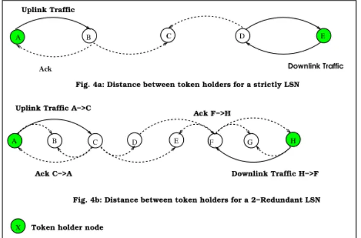
from node to node before reaching the sink, a spatial reuse mechanism can be used to have several tokens circulating in the network at the same time. In order to avoid collisions and interferences, the distance between two nodes being in the token holding state depends on the communication range of each node, and on the possibility of a downlink traffic. For instance, in a strictly LSN without downlink traffic, two token holder nodes have to be separated by at least two nodes (ie three hops). In a strictly LSN with downlink traffic, this distance is increased to three nodes (ie four hops). This is depicted on Fig. 3a. In Fig. 3a, as node A is token holder,
A B C D E F G H
X
A B C D E
Ack
Uplink Traffic
Fig. 4a: Distance between token holders for a strictly LSN Uplink Traffic A−>C
Ack F−>H
Downlink Traffic H−>F Ack C−>A
Fig. 4b: Distance between token holders for a 2−Redundant LSN
Token holder node
Downlink Traffic
Figure 3: Distance between token holders
the part of the LSN including nodes A, B, C and D can be considered as a cluster moving from node to node each time the shuttle duration (ShuDur) has expired. For this kind of strictly LSN, the cluster size (CluSize) must be four hops. If the radio range of each node allows the possibility to exchange with its two-hop neighbors, the spatial reuse becomes less efficient, as it requires an increase in the distance between two nodes being in the token holding state. As shown in Fig. 3b, for a 2-redundant LSN, two token holder nodes have to be separated by at least four nodes when the traffic is only for the sink, and by six nodes when a downlink traffic is possible. The cluster size is respectively 5 and 7. The minimal distance between two successive token holder nodes has a strong impact on the network performance and on the token production carried out by the allocator. For a given token holding time (T1 +
T2 + T’2 as defined in Fig. 2), the minimal period of token production is given by TT oken(min) = ShuDur x CluSize. The
time separating two consecutive tokens TT okenmust be greater
than TT oken (min); the choice of this period has to be done
by considering the following factors: energy autonomy of the nodes, expected latency, profile of the offered traffic load, and so on.
B. Effects of the FIFO queue behavior
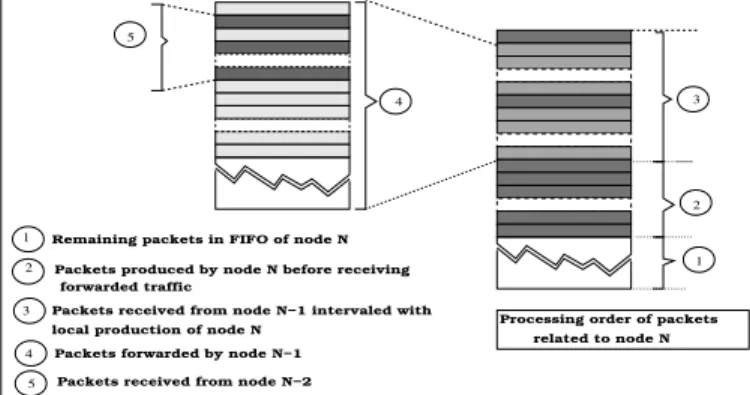
Let us consider the case of a strictly LSN topology, if a downlink traffic is possible, a node has to queue the traffic locally produced during three quarters of its time. During the remaining quarter of its time, the node is token holder and it has to queue the local traffic in addition to the traffic forwarded by the previous node of the LSN. The content of the queue of a current node can be divided in three parts as shown in Fig. 4. At the bottom of the FIFO, some packets eventually remain if the size of the previously used shuttle was too short to completely empty the queue when the node was token holder. The local traffic production is queued during the major part of the token period TT oken. Then, at the top of the FIFO, the
packets forwarded by the token holder node are interleaved with the local production. The FIFO content presented in Fig. 4
1 2 4 5 3 1 2 3 4 5
Remaining packets in FIFO of node N Packets produced by node N before receiving
forwarded traffic
Packets received from node N−1 intervaled with local production of node N
Packets forwarded by node N−1 Packets received from node N−2
Processing order of packets related to node N
Figure 4: Content of the FIFO of a current node
can be considered as a recursive structure meaning that the third part of the queue is a kind of copy of the content of the previous node FIFO. Thus, in such a network, the traffic is accumulated node after node and saturation appears when the FIFO of the current node is not able to queue the traffic forwarded by the previous nodes. Nevertheless, uplink traffic is always queued at the top of the FIFO and is exposed to the queue overload effect. Packets coming from the Allocator are the first to be dropped in case of FIFO overflow.
This is what we call the clipping effect. Packets generated by the allocator or by the first nodes of the linear network are exposed to be systematically dropped before arriving to the sink, when the offered load of the network is too large for the capacity of the FIFO nodes.
V. PERFORMANCE EVALUATION
A. Main objectives
In this paper, we focus on the delivery ratio for a given queue size. It represents the number of packets received suc-cessfully by the sink for a given node. The delivery probability
of a packet depends on the overall load, but also on the number of hops before reaching the sink. For a LSN using a Token-based MAC protocol such as ours and for a given offered load, we show that the delivery ratio can be more easily predictable for any source node. We focus on four nodes: node 1, node 8, node 14 and node 15. Node 1 is the first node of the topology, and does not receive traffic from any node. Thus, node 1 only considers local traffic. Node 14 and 15 are the nodes closer to the sink: they are the nodes with the largest accumulated traffic. Finally, node 8 is a current node at the center of the topology: it receives traffic from others nodes, in addition to its own local traffic production.
B. Simulation setup
We perform our simulations on NS2 (version 2.32). Our results are given for a linear network of sixteen nodes: node 1 (the Allocator), is on the left, and node 16 (the Sink), is on the right. Local traffic is produced pseudo-periodically and starts randomly between 0 and 1 second, and independently for each node. A given current node might receive traffic to be forwarded when one of its neighbors becomes token holder. We suppose in the following that all the nodes of the LSN have the same queue managed in a first in first out (FIFO) manner. The capacity of this queue can be expressed by the number of packets (FiFoSize) it can contain. The size of the reverse traffic is ignored in our simulations. We suppose also that all the packets have the same size. Table I presents the simulation parameters.
Table I: Simulation parameters Parameter Value Downlink traffic time 10 ms Uplink traffic time 240 ms Token packet size 11 bytes Data packet size 100 bytes Number of repetitions 50 Physical Layer 802.15.4 Transmission Power -5 dBm FIFO size 50-60 Distance between two nodes
in Strictly LSN
90 meters Distance between two nodes
in redundant LSN
45 meters
Data transmission rate [10-100] packets/s
C. Simulation results
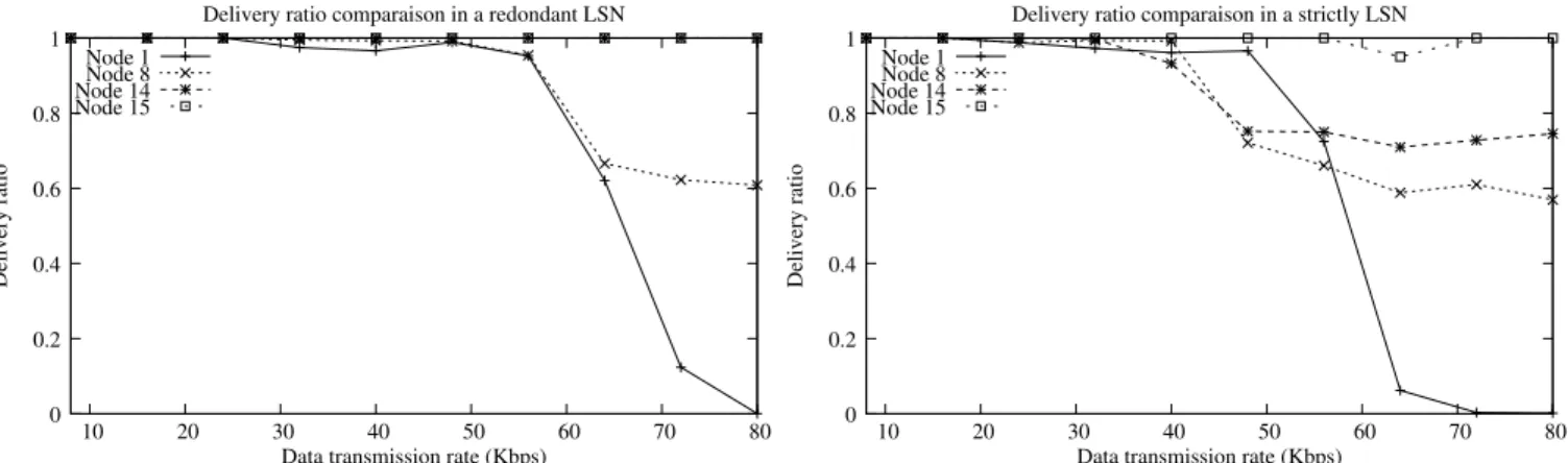
Delivery ratio is evaluated according to global offered load and LSN density (strictly and 2-redundant). Fig. 5a and Fig. 5b show the simulation results for nodes 1, 8, 14 and 15. The impact of the clipping effect is particularly clear on the two curves. The accumulated packets are exposed to be dropped when the number of accumulated packets exceeds the FIFO size. The packets queued near the top of the FIFO are the first to be dropped. It is why in overload conditions, the delivery rate of packets depends on the length of the forwarding path, and packets coming from nodes far from the sink are exposed to be systematically discarded. It explains why delivery ratios for packets produced by node 1 and node 15 are so different when the offered load is over 60 Kbps.
Node 1 Node 8 Node 14 Node 15 0 0.2 0.4 0.6 0.8 1 10 20 30 40 50 60 70 80 Delivery ratio
Data transmission rate (Kbps) Delivery ratio comparaison in a redondant LSN
(a) Delivery ratio comparison for nodes 1, 8, 14 and 15 in a redundant LSN for queue size=50
Node 1 Node 8 Node 14 Node 15 0 0.2 0.4 0.6 0.8 1 10 20 30 40 50 60 70 80 Delivery ratio
Data transmission rate (Kbps) Delivery ratio comparaison in a strictly LSN
(b) Delivery ratio comparison for nodes 1, 8, 14 and 15 in a strictly LSN for queue size=50
Figure 5: Delivery ration comparison
This impact is mitigated when the LSN is not strictly linear because the packet accumulation is spread over the FIFO of nodes in range of the sink. Nevertheless, clipping effect is more significant in a strictly than a redundant LSN. Packets coming from the farthest node do not reach the sink when data transmission crosses 70 Kbps in a strictly LSN while 80 Kbps in a 2-redundant LSN. Additionally, the delivery ratio for the others nodes is more important in the 2-redundant LSN than in strictly LSN. For an offered load varying from 10 to 100 packets/s, the average delivery ratio varies from 100 to 62% for 2-redundant LSN and from 100 to 58% in a strictly LSN. This is due to routing possibility allowed by a 2-redundant LSN: two nodes (14 and 15) send data frames directly to the sink instead of one node in a strictly LSN. The FIFO of node 15 is not concerned by traffic forwarded by node 14.
The end-to-end delay has a similar behavior as the delivery ratio. Indeed, a comparison study for nodes 1, 8, 14 and 15 according to global offered load and LSN density (strictly and 2-redundant) shows that of course end-to-end delay increases as the number of hops increase, this for the two types of LSN. Nevertheless, for each node, the end-to-end delay is constant if the offered load remains under the saturation load (50 packets/s for a strictly LSN and 50 packets/s for a 2 redundant LSN [13].
VI. CONCLUSION
In this paper, we propose a token based MAC protocol adapted to linear sensor networks. We study this protocol in the case of two different topologies. We show how the token is propagated from node to node in the network and how the token generation period is calculated in order to avoid packet collisions and limits the effects of the token losses before reaching to the sink. We highlight what we call the clipping effect. This is illustrated in our simulation results where we study the performances of our protocol in terms of delivery ratio for a given offered load.
The queue management could be improved by using a priority policy to privilege traffic from the farthest nodes or by aggregating packets to increase performance of the kind of LSNs in an energy saving manner.
REFERENCES
[1] M. Li and Y. Liu, “Underground coal mine monitoring with wireless sensor networks,” ACM Trans. Sen. Netw., vol. 5, no. 2, pp. 10:1–10:29, Apr. 2009.
[2] I. Jawhar, M. Nader, and K. Shuaib, “A framework for pipeline infrastructure monitoring using wireless sensor networks,” in The Sixth Annual Wireless Telecommunications Symposium (WTS 2007), Pomona, California, USA, April 2007.
[3] M. Zimmerling, W. Dargie, and J. M. Reason, “Localized power-aware routing in linear wireless sensor networks,” in The 2nd ACM Workshop on Context-Awareness for Self-managing Systems, Sydney, Australia, May 22 2008.
[4] N. Wang, Q. Meng, T. Li, and Q. Ma, “Research on linear wireless sensor networks used for on-line monitoring of rolling bearing in freight train,” in 9th International Conference on Damage Assessment of Structures, 2011.
[5] M. Ergen, D. . Lee, R. S. engupta, and P. Varaiya, “Wtrp-wireless token ring protocol,” in Vehicular Technology, IEEE Transactions, vol. 53, November 2004, pp. 1863 – 1881.
[6] S. Xianpu, Z. Yanling, and L. Jiandong, “Wireless dynamic token protocol for manet,” in International Conference on Parallel Processing Workshops, November 2007.
[7] P. Udayakumar, V. Vyas, and O.P, “Medium access control with token approach in wireless sensor network,” in International Journal of Computer Applications (0975 – 8887), April 2012.
[8] P. Udayakumar, R. Vyas, and O. Vyas, “Token bus based mac protocol for wireless sensor networks,” in International Journal of Computer Applications (0975 – 8887), April 2012.
[9] J. Liu, M. Suzuki, D. . Lee, and H. morikawa, “A token scheduled high throughput multi-channel data collection protocol for wireless sensor network,” in Proc. IEEE Veh. Technol. Conf., June 2013.
[10] G. Fan, J. Li, W. Liu, and Y. Zhao, “An enhanced dynamic token protocol for underwater accoustic sensor networks,” in International journal on smart sensing and intelligent systems, vol. 4, December 2012.
[11] M. D. Sarr, F. Delobel, M. Misson, and I. Niang, “Automatic discovery of topologies and addressing for linear wireless sensor networks,” in IFIP Wireless Days, Dublin, Ireland, Nov 21-23 2012.
[12] E. H. M. Ndoye, F. Jacquet, M. Misson, and I. Niang, “Evaluation of rts/cts with unslotted csma/ca algorithm in linear sensor networks,” in NICST 2013, September 2013.
[13] E. H. M. Ndoye, F. Jacquet, and M. Misson, “Using a token approach for the mac layer of linear sensor networks: Impact on the end-to-end delay,” Universit´e Blaise Pascal de Clermont-Ferrand, Tech. Rep., September 2013.