HAL Id: in2p3-00120586
http://hal.in2p3.fr/in2p3-00120586
Submitted on 15 Dec 2006
HAL is a multi-disciplinary open access
archive for the deposit and dissemination of
sci-entific research documents, whether they are
pub-lished or not. The documents may come from
teaching and research institutions in France or
abroad, or from public or private research centers.
L’archive ouverte pluridisciplinaire HAL, est
destinée au dépôt et à la diffusion de documents
scientifiques de niveau recherche, publiés ou non,
émanant des établissements d’enseignement et de
recherche français ou étrangers, des laboratoires
publics ou privés.
Beam Dynamics Studies for the Spiral-2 Project
J.-L. Biarrotte, P. Bertrand, D. Uriot
To cite this version:
J.-L. Biarrotte, P. Bertrand, D. Uriot. Beam Dynamics Studies for the Spiral-2 Project. Tenth
Euro-pean Particle Accelerator Conference ”EPAC’06”, Jun 2006, Edinburgh, United Kingdom.
pp.1930-1932, 2006. �in2p3-00120586�
BEAM DYNAMICS STUDIES FOR THE SPIRAL-2 PROJECT
J-L. Biarrotte
#, CNRS / IPN Orsay, France
P. Bertrand, GANIL, Caen, France
D. Uriot, CEA Saclay, France
Abstract
The SPIRAL-2 superconducting linac driver, which aims at delivering 5 mA, 40 MeV deuterons and 1 mA, 14.5 A.MeV q/A=1/3 heavy ions, is now entering the construction phase. It is composed of an injector with two ECR sources and one 88 MHz RFQ, followed by a superconducting section based on 88 MHz independently-phased quarter-wave cavities with room-temperature focusing elements. This paper presents the status of the beam dynamics studies recently performed during this construction phase: freezing of the low-energy beam transport lines of the injector, consolidation of the mass separation system, and analysis of some linac extended capabilities like the proton acceleration.
INTRODUCTION
The SPIRAL-2 project aims at building at GANIL a new ISOL-type facility for the production of high intensity rare isotope beams. The project has now entered the construction phase, for first beam production around 2012. The driver accelerator must accelerate a 5 mA CW deuteron beam up to 40 MeV, and a 1 mA CW ion beam with mass-to-charge ratio A/q=3 up to 14.5 A.MeV. It must also have the capability to accelerate protons (new requirement) and, in a future stage, to host a second injector to accelerate ions of mass-to-charge ratio A/q up to 6. Naturally, this driver accelerator is a linac with independently-phased superconducting cavities for high safety and maximum flexibility in the acceleration of different ion species with different charge-to-mass ratios at various final energies. The linac is divided into 3 main parts: injector, superconducting linac, and high-energy beam transport lines (HEBTs).
The injector includes two ECR sources (one for deuterons and one for A/q=3 ions) with their associated low-energy beam transport lines (LEBTs). Both lines merge before entering a single room-temperature RFQ cavity, that bunches and accelerates the beam at 88 MHz up to 0.75 A.MeV. A medium-energy beam transport line (MEBT) then injects the beam into the superconducting linac; this MEBT includes a fast chopping system, and also allows the connection of a possible second A/q=6 ion injector.
The superconducting linac accelerates the beam up to the final energy (40 MeV maximum for deuterons, 14.5 A.MeV maximum for A/q=3 ions, 7 A.MeV for A/q=6 ions). It is composed of 88 MHz quarter-wave resonators of two different types: beta 0.07 (12 cavities) and beta 0.12 (14 cavities + 4 possible spare ones). These superconducting cavities operate at safe accelerating fields (6.5 MV/m nominal). They are grouped in short and
modular cryomodules, with 1 and 2 cavities per cryostat for the beta 0.07 and 0.12 sections respectively, for a total length of about 25 metres.
Finally, the beam can be distributed to three different locations. The first HEBT line goes straight to a beam dump. The second (and main) one transports the beam to the radioactive ion production cave containing the 200 kW target-ion-source system, with special focusing to obtain a uniform power distribution on the neutron converter. The third HEBT line transports and matches the beam to the stable ion experimental areas.
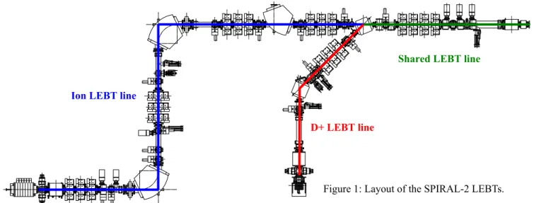
More details can be found in references [1-5]. In this paper, we will present the status of the beam dynamics studies performed since the beginning of the construction phase at the end of 2005, which have mainly consisted of freezing the layout of the injector low-energy beam transport lines, as is shown in Figure 1. The capability of the SPIRAL-2 linac to fulfil some new requirements (proton acceleration, low-energy beams transport in the HEBT) will also be briefly discussed.
THE DEUTERON LEBT LINE
The consolidated deuteron LEBT line is very similar to the one described in [5]. It is based on the use of a solenoid, that refocuses the beam exiting from the source, followed by an achromatic section that ensures an efficient separation of the deuteron D+ beam from the
main pollutants (D2+, D3+ and heavier 1+ ion beams),
while avoiding any beam degradation due to possible fluctuations of the source’s voltage or of the bending magnets’ field. The achromat is composed by one quadrupoles triplet surrounded by two 45° dipoles with 50 cm curvature radius, deviating the beam to the right side; the dipoles are sector-magnets (no edge angle) so as to better balance the envelope excursions in both planes.
At the exit of the source, it is assumed, based on recent measurements on the SILHI source [6], that the nominal deuteron beam has an normalized rms emittance of 0.1 π.mm.mrad in both planes, with known Twiss parameters and an energy of 40.27 keV. The nominal D+
current is set to 6.5 mA. The main unknown factor is the way the space charge forces will be compensated along the line, due to electron production by the residual gas ionisation. From measurements performed on the LEBT line of IPHI [7], a space charge compensation of 80% has been chosen as a reference, but values from 50% up to 100% have been investigated to improve the robustness of the optical design. In this respect, the solenoid comprises 2 independent coils to ease the beam tuning, and its distance from the first dipole has been optimised to cope with various space charge compensation values.
____________________________________________
WEPCH007 Proceedings of EPAC 2006, Edinburgh, Scotland
1930 05 Beam Dynamics and Electromagnetic Fields D01 Beam Optics - Lattices, Correction Schemes, Transport
The matching of the line is done by minimising the beam size inside the dipoles, using 4 beam profilers located at both sides of the two bends. The 2 mA of pollutants are mainly lost in the drift following the solenoid (~35W), inside the first dipole (~25W), and in the following drift (~15W). All these locations will be cooled down and pumped to reach a vacuum level of around 10-6 mbar. Multiparticle simulations are performed
using the TraceWin/Partran package [8], with a Gaussian distribution truncated at 4σ at the source exit. The √6×σ
(~95%) envelopes are shown in Figure 2 from the source up to the RFQ. Along the single D+ LEBT line, the
transmission is 100%, and the emittance growth is estimated to be about +100%.
TraceWin - CEA/ DSM/ DAPNIA/ SACM
Position (m) 10 8 6 4 2 0 X ( m m ) 80 60 40 20 0 -20 -40 -60 -80 Position (m) 10 8 6 4 2 0 Y ( m m ) 80 60 40 20 0 -20 -40 -60 -80
Figure 2: Deuteron envelopes in the SPIRAL-2 LEBT.
THE ION LEBT LINE
The main goal of the ion LEBT line is to separate efficiently the different masses and charge states coming out from the source. For this purpose, a double-focusing 90° dipole is used, with 60 cm curvature radius and 26.565° edge angles. One solenoid and 3 quadrupoles are used to match the beam to the dipole by creating the object point at 1.2 m before the bend entrance, and the
image point at 1.2 m after the bend exit, where the slit system is located for the ion selection. An associated hexapole located before the dipole is used to minimize the non-linearities induced by such large beam extensions inside the bend. Additional slits are also used near the object point to roughly separate the beam from the most distant pollutants. After the selection slit, 3 quadrupoles and a second 90° dipole and associated hexapole complete the achromatic left/right double-deviation. The following 2 quadrupoles triplets are only used to transport the beam to the shared LEBT line. Between the triplets, a free location allows the possibility to add a dipole to connect a possible future injection line.
Based on measurements made with oxygen at the A-Phoenix source [9], a normalized rms emittance of 0.2 π.mm.mrad in both planes has been chosen for the nominal A/q=3 ion beam at the exit of the 60 kV source. But because this source will produce several different beams, values up to 0.4 π.mm.mrad have been assumed for safety. The nominal ion current at the source exit is set to 1.3 mA, with 70% space-charge compensation along the line. The matching of the beginning of the line is done by adjusting the beam size at the image point with a profiler so as to get the required mass separation. Multi-particle simulations show that a practical resolution of more than 100 can be obtained without significant transmission degradation. In such a system, the ~5 mA of undesirable ions are mainly lost in the dipole chamber (~150W in the case of oxygen); the rest is intercepted by the first triplet (~10W), the different slits (~50W in total), the hexapole (~15W) and the drift following the dipole (~40W). The hot locations will be cooled down and pumped to reach a vacuum level of around 10-8 mbar.
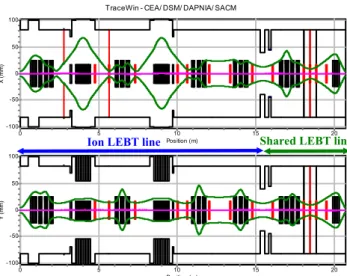
After the selection slit, the matching is done with several profilers so as, first, to obtain a symmetric optic in the achromat, and second, to ensure a smooth transport up to the shared LEBT line, especially minimizing the envelope excursions through the deuteron 45° dipole. The 6σ (~95%) envelopes are shown in Figure 3 from the source up to the RFQ. Along the single ion LEBT line, the transmission is 96% (losses are located on the slits), and the emittance growth is about +20%.
D+ LEBT line Shared LEBT line
Figure 1: Layout of the SPIRAL-2 LEBTs.
Ion LEBT line
Shared LEBT line
D+ LEBT line
Proceedings of EPAC 2006, Edinburgh, Scotland WEPCH007
05 Beam Dynamics and Electromagnetic Fields
D01 Beam Optics - Lattices, Correction Schemes, Transport
TraceWin - CEA/ DSM/ DAPNIA/ SACM Position (m) 20 15 10 5 0 X ( m m) 100 50 0 -50 -100 Position (m) 20 15 10 5 0 Y ( m m ) 100 50 0 -50 -100
Figure 3: Ion envelopes in the SPIRAL-2 LEBT.
THE SHARED LEBT LINE
The last part of the SPIRAL-2 LEBT line is shared by both deuteron and A/q=3 ion beams. It is composed by 4 quadrupoles and one solenoid, whose main goal is to correctly match the beam to the RFQ input. Before the quadruplet, a 5 kV slow chopper (several tens of ns rise time) can be used to produce pulsed beams with duty cycles down to 0.1%. This chopper deviates the beam in the horizontal plane towards a dedicated cooled scrapper. Between the quadruplet and the solenoid, a symmetric 3-slit system with its associated profilers is used to remove the halo and define the beam emittance. For this purpose, the quadruplet is tuned to create a beam double-waist at the central slit position, with the same desired size in each plane. This round beam is then focused using the last solenoid, that comprises 2 independent coils like the one of the D+ LEBT line, so as to create the correct beam size
and divergence at the RFQ input.
In total, the transmission of the whole LEBT line in the nominal cases reaches 90%, with normalized rms emittances at the RFQ input of about 0.15 π.mm.mrad for deuterons and 0.2 π.mm.mrad for A/q=3 ions.
LINAC EXTENDED CAPABILITIES
Some extended capabilities of the SPIRAL-2 linac have been recently analyzed to try to fulfil new experiments needs. It has been first checked that the acceleration of protons is feasible in the SPIRAL-2 linac [10]. The deuteron source can be used to produce a 6.5 mA proton beam at 20.15 keV with characteristics very similar to those of the deuteron beam. The bunching and accelerating process up to 0.75 MeV is possible in the RFQ, lowering the mean voltage on the vanes from 100 kV (A/q=3 ion) or 70 kV (D+ case) down to 43 kV. The superconducting linac then accelerates the proton beam up to 33 MeV, or even 40 MeV if 2 of the 4 spare cavities are used. The transverse emittance growth in the linac is substantially higher than in the deuteron case
(+70% vs +20%) due to higher space-charge effects, but the situation stays acceptable in terms of beam losses.
Finally, the possibility to tune the linac output energy and to transport low energy beams (down to 2 A.MeV) towards stable ion experimental areas is being considered. The output energy tunability is possible using two methods [11]: switching off and detuning the useless accelerating cavities, or using some of them as bunchers to maintain the beam time-structure, taking advantage of the first harmonic of the transit time factor in the β=0.12 section. In the second case, because of a higher space charge and stronger steering effects in the quarter-wave cavities, the transmission is slightly degraded in the superconducting linac, but still stays acceptable (>99.8%). The low-energy beam is then transported using a 30 metres HEBT line. This line, which is presently under study, will have in particular to include superconducting bunchers (at least 5) to keep the beam time-structure until the stable ion experimental areas.
CONCLUSION
The layout of the SPIRAL-2 injector low-energy beam transport lines is presented. This design will be definitely frozen in September 2006, and the first call-for-tenders should be launched end 2006. The possibility to accelerate protons with SPIRAL-2 has been checked, and the possibility to produce very low energy stable beams is currently under final evaluation.
REFERENCES
[1] T. Junquera & al., “Superconducting driver linac for the new Spiral-2 radioactive ion beam facility at GANIL”, these proceedings.
[2] M.H. Moscatello & A. Mosnier, “Design of the high intensity exotic beams Spiral 2 project”, PAC’05, Knoxville, TN, USA.
[3] “The SPIRAL2 project APD report”, January 2005. [4] R. Duperrier & al., “Status report on the beam
dynamics developments for the Spiral 2 project”, EPAC’04, Lucerne, Switzerland.
[5] “Beam dynamic development for the SPIRAL2 project – Final report”, SPIRAL2 technical report, October 2004.
[6] R. Gobin et al., “SPIRAL2 – Rapport de fin APD - Source ECR type SILHI pour la production de deutons”, SPIRAL2 technical report, February 2005. [7] P.-Y. Beauvais et al., “Status report on the
construction of the French high intensity proton injector (IPHI)”, EPAC’02, Paris, France
[8] R. Duperrier, N. Pichoff, D. Uriot, “CEA Saclay codes review”, ICCS Conference, Amsterdam, 2002. [9] T. Thuillier, SPIRAL2 technical note, January 2006. [10] D. Uriot, “Etude de la possibilité d’accélérer des
protons dans le linac SPIRAL2”, SPIRAL2 technical report, April 2006.
[11] J-L. Biarrotte, “Etude de la flexibilité en énergie du linac supra”, SPIRAL2 technical note, May 2004.
Ion LEBT line Shared LEBT line
WEPCH007 Proceedings of EPAC 2006, Edinburgh, Scotland
1932 05 Beam Dynamics and Electromagnetic Fields D01 Beam Optics - Lattices, Correction Schemes, Transport