HAL Id: hal-00947223
https://hal.inria.fr/hal-00947223
Submitted on 14 Feb 2014
HAL is a multi-disciplinary open access archive for the deposit and dissemination of sci-entific research documents, whether they are pub-lished or not. The documents may come from teaching and research institutions in France or abroad, or from public or private research centers.
L’archive ouverte pluridisciplinaire HAL, est destinée au dépôt et à la diffusion de documents scientifiques de niveau recherche, publiés ou non, émanant des établissements d’enseignement et de recherche français ou étrangers, des laboratoires publics ou privés.
Antenna Ultra Wideband Enhancement by
Non-Uniform Matching
Mohamed Hayouni, Ahmed El Oualkadi, Fethi Choubani, T. H. Vuong,
Jacques David
To cite this version:
Mohamed Hayouni, Ahmed El Oualkadi, Fethi Choubani, T. H. Vuong, Jacques David. Antenna Ultra Wideband Enhancement by Non-Uniform Matching. Progress In Electromagnetics Research Letters, EMW Publishing, 2012, 31, pp.121-129. �hal-00947223�
ANTENNA ULTRA WIDEBAND ENHANCEMENT BY NON-UNIFORM MATCHING
M. Hayouni1, *, A. El Oualkadi2, F. Choubani1, T. H. Vuong3, and J. David3
1Innov’COM, Sup’COM, University of Carthage, Tunisia 2LabTIC, ENSA de Tanger, Tanger BP 1818, Morocco 3ENSEEIHT, France
Abstract—In this paper, antenna ultra wideband enhancement by non-uniform matching is proposed. The antenna consisted of a rectangular shaped radiator with two convex circled corners. Simulated results using CST Microwave Studio and measured results of a fabricated antenna concord well to prove that it can operate from about 3.5 GHz to 4.6 GHz and from 7.4 GHz to 12.7 GHz for S11(dB) <
−10 dB. In addition, a good impedance matching is noted in the IEEE radar engineering X band range since the return loss coefficient remains below −50 dB value at 9.5 GHz and can reach −45 dB at 11 GHz. A current density comparison at 11 GHz, supporting our argument, between a stepper corner and convex corner demonstrates that the current density can reach 52 A/m with a convex corner whereas it does not exceed 33 A/m for the antenna with a stepper corners. Radiation patterns at various frequencies and peak gains show clearly interesting features of such antennas.
1. INTRODUCTION
Miniaturization and bandwidth enhancement are becoming design considerations for practical applications of microstrip antennas. Eventually, researches to reach compact and broadband operations of microstrip antennas become increasingly expanded. Some developments in allied branches are now being investigated in antennas applications. Various recent basic principles of broadband design are deployed in the literature. Indeed, the investigation into the
Received 10 March 2012, Accepted 12 April 2012, Scheduled 18 April 2012 * Corresponding author: Mohamed Hayouni (mohamed.hayouni@supcom.rnu.tn).
122 Hayouni et al.
performance of proximity coupled stacked patches by the exploration of the relationship required between the dielectric layers, the dimensions of the stacked radiators and the relative location of the feed can achieve a broadband behaviour in excess of 20% as studied in [1]. The optimization of the impedance matching through narrow cavity backed configuration, as described in [2], can enhance the bandwidth of the proposed antenna to more than 40% (VSWR < 2) since it can provide a larger effective coupling than the conventional proximity-coupled antenna without a narrow cavity backed configuration. A low Q factor of the magnetic wall under the patch created by a low dielectric constant or larger thickness of the substrate is also an available broadband technique [3]. The impedance matching of the feed by probe compensation, using L-shape probe and any reactive loading as evoked in [4], is another basic principle of broadband design. In addition to integration slots in the ground plane of microstrip planar antennas as deployed in [5, 6], or using a rigged ground plane [7] or slots in the radiator as published in [8–12], compact operation with enhanced impedance bandwidth can be obtained. Indeed in [8], the authors have proposed a UWB antenna; it consisted of a rectangular patch with two steps, a single slot on the patch, and a partial ground plane. The proposed antenna was designed to operate from 3.2 to 12 GHz which the measured and simulated return loss coefficients do not go beyond −27 dB. In addition, in [8], the authors have proposed to replace the rectangular slot inserted into the compact UWB planar antenna proposed in [8] by a U slot in order to reject the WIFI band frequency around 5.6 GHz, and the return loss coefficient does not go below −25 dB through the impedance bandwidth of the radiator. In this paper, we propose an ultra wide band antenna enhancement by non-uniform matching. Indeed, rectangular shaped planar antennas with concave and convex circled corners are investigated in order to excite different electric lengths with smooth variations. The later are adjusted to lessen the VSWR between the main resonance frequencies of the rectangular partial grounded patch antenna. A current density comparison at certain frequencies with the prototype proposed in [8] with stepper corners will be studied in order to interpret the high impedance matching between the microstrip feed line and the load in order to prove the efficiency of non-uniform patch profiles.
2. ANTENNA DESIGN
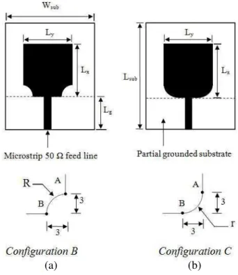
The proposed antennas with the two configurations B and C are sketched in Figure 1. The two designs are a transfer from the configuration A published in [8] with steppers corners to
non-(a) (b)
Figure 1. Geometries of the proposed antennas: (a) top view of the configuration B and (b) top view of the configuration C.
uniform geometrical corners. The configurations B and C consisted, respectively, of a rectangular shaped perfect electric conductor printed on a partial grounded FR4 epoxy dielectric substrate of 4.4 permittivity, 1.6 mm thick, Lsub = 35 mm length and Wsub = 30 mm
width dimensions. The radii of the concave and convex corners are respectively R and r. The proposed radiators are compact since they are defined by Lx = 14.5 mm and Ly = 15 mm dimensions. The feeding
technique consisted of a 50 Ω microstrip feed line with a length of Lg = 11.5 mm. Various simulations were performed in order to view
the radius effect on the impedance matching of each antenna in order to select the suitable form and its radius.
2.1. Configuration B
Various electromagnetic simulations of the prototype B were performed for different radii R to view its impact on the impedance matching.
124 Hayouni et al.
Figure 2. Return loss of the rectangular shaped planar antenna with two concave circled corners for various radii.
Figure 3. Return loss coefficient of the rectangular shaped planar antenna with two convex circled corners for various radii.
Indeed, as depicted by Figure 2, the return loss can reach −33 dB at 12.8 GHz for R = 5.4 mm. This return loss coefficient pick may slightly increase if R decreases. The configuration B is better than the configuration A in terms of impedance matching especially in the IEEE radar X band.
2.2. Configuration C
Various electromagnetic simulations of the configuration C (Fig-ure 1(b)) versus r were also performed in order to study the behaviour of the return loss coefficient versus the convex circled curve radius r. Indeed, as depicted by Figure 3, we note a good impedance matching in the IEEE radar engineering X band range since the return loss can reach −50 dB at 11.25 GHz for r = 5.4 mm and is less than −50 dB at 9.5 GHz for r = 3 mm. The best simulated prototype which cor-responds to the best impedance matching corcor-responds to r = 3 mm radius.
Compared to the configuration B, the Configuration C provides a better impedance matching in the IEEE radar X band. In the rest of this paper, we propose to present a return loss comparison between measured and simulated results of a fabricated antenna based on the configuration C with r = 3 mm radius. Radiation patterns at some frequencies and peak gain will also be presented.
(a) (b)
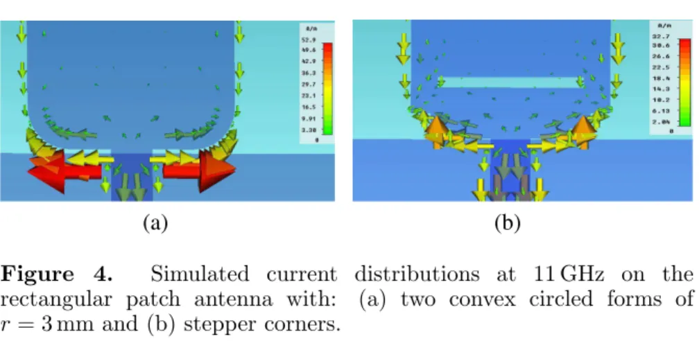
Figure 4. Simulated current distributions at 11 GHz on the rectangular patch antenna with: (a) two convex circled forms of r= 3 mm and (b) stepper corners.
2.3. Current Density
The current distribution normally gives an insight into the physical behaviour of the antenna. In simulation, antennas with stepper and convex circled corners are investigated at various frequencies. Indeed, Figure 4 shows the current distribution at 11 GHz frequency supporting our argument of the convex circled corners geometry contribution in the impedance matching in IEEE radar engineering X band range compared to stepped two corners contribution. Higher current density can be observed at the two convex circled corners of the UWB radiator that reaches 52 A/m. This current density value is higher than the current density at the stepper corners radiator presented in [8] that does not exceed 32.5 A/m at the same frequency. It is obvious that the input power is much more efficiently sent to the radiator when using two convex corners. This supports the importance of non-uniform geometry such as convex circled geometry between the feed line and the antenna as a good impedance matching tool.
3. RESULTS AND DISCUSSION 3.1. S Parameters
A planar UWB partial grounded substrate antenna with two convex circled corners of r = 3 mm radius was fabricated and measured using a vector network analyzer Anritsu 37369C (40 MHz to 40 GHz) where the calibration plane is the SMA connector jack used to connect the antenna as depicted by Figure 5. Figure 6 proves a strong correlation between measured and simulated return loss coefficients. Indeed, the two curves concord from 3.55 GHz to 4.6 GHz and from 7.4 GHz to 12.7 GHz for S11(dB) < −10 dB. Measured results also prove the tight
126 Hayouni et al.
Figure 5. Top view of the fabricated rectangular patch with two inserted convex circled corners of r = 3 mm.
Figure 6. Measured and simu-lated return loss of the rectangu-lar patch with two inserted con-vex circled corners of r = 3 mm.
(a) (b)
Figure 7. Normalized measured radiation patterns of the proposed UWB antenna at 3.5 GHz: (a) E-plane; (b) H-plane.
influence of the circled convex corners upon the impedance matching of the microstrip feed line and the radiator. It is noticed that the return loss coefficient falls to −50 dB at 9.5 GHz and −45 dB at 11.1 GHz. 3.2. Radiation Pattern
Plots of Figures 7–9 show the normalized measured radiation patterns at three individual frequencies 3.5, 5.8, and 11 GHz, respectively, of the fabricated antenna. It is seen that the radiation pattern is stable. It is almost uniform (nearly omnidirectional) at E and H planes in both
(a) (b)
Figure 8. Normalized measured radiation patterns of the proposed UWB antenna at 7.5 GHz: (a) E-plane; (b) H-plane.
(a) (b)
Figure 9. Normalized measured radiation patterns of the proposed UWB antenna at 11 GHz: (a) E-plane; (b) H-plane.
co- and cross-polarizations for the selected in-band frequencies. At 3.5 GHz and 7.5 GHz frequencies, the E-plane radiation patterns are split into a few radiation beams. This undesired phenomenon cannot be abolished in physics and also exists in many other UWB antennas, especially planar monopole antenna [13].
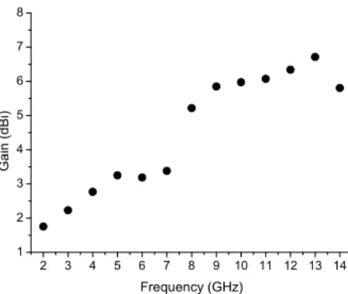
The simulated peak gain of the proposed antenna at various frequencies is shown in Figure 10. An increasing peak gain is observed from 1.8 to 6.8 dBi in the frequency range from 2 to 13 GHz. A slight reduction in gain is observed for frequencies higher than 13 GHz resulting in a drop in antenna efficiency at the higher end of the frequency range of simulation.
128 Hayouni et al.
Figure 10. Simulated peak gain of the proposed antenna. 4. CONCLUSION
A rectangular shaped compact UWB antenna with two convex circled corners has been presented in this paper. The simulated results performed show reasonable agreement with the measured ones. The frequency range obtained for S11(dB) < −10 dB extends from 3.55 GHz
t o 4.6 GHz and from 7.4 GHz to 12.7 GHz. Measured results also prove the good effect of the circled convex corners on the impedance matching of the microstrip feed line and the radiator. A wideband matching is achieved with extremely low return loss, as low as −50 dB at 9.5 GHz and −45 dB at 11.1 GHz.
REFERENCES
1. Waynes, S., T. Rowe, and R. B. Waterhouse, “Investigation into the performance of proximity coupled stacked patches,” IEEE Transaction on Antennas and Propagation, 1693–1698, Jun. 2006. 2. Sun, D. and L. You, “A broadband impedance matching method for proximity coupled microstrip antenna,” IEEE Transaction on Antennas and Propagation, 1392–1397, Apr. 2010.
3. Kelly, J. R., P. S. Hall, and P. Gardner, “Planar band-notched UWB antenna,” 3rd Conference Eucap’2009, 1636–1639, Mar. 2009.
4. Wong, K. L., Compact and Broadband Microstrip Antennas, Wiley, NY, 2002.
5. Sim, C.-Y.-D., W.-T. Chung, and C.-H. Lee, “Compact slot antenna for UWB applications,” Antenna and Wireless Propagation Letters, 62–66, 2010.
6. Dastranj, A. and H. Abiri, “Bandwidth enhancement of printed E-shaped slot antennas fed by CPW and microstrip line,” IEEE Transaction on Antennas and Propagation, 1402–1407, Apr. 2010. 7. Lin, C.-C. and H.-R. Chuang, “A 3–12 GHz UWB planar triangular monopole antenna with ridged ground-plane,” Progress In Electromagnetics Research, Vol. 83, 307–321, 2008.
8. Choi, S. H., J. K. Park, S. K. Kim, and J. Y. Park, “A new ultra-wide band antenna for UWB application,” Microwave and Optical Technologies Letters, 399–401, Mar. 2004.
9. Duroc, Y., T.-P. Vuong, and S. Tedjini, “A time/frequency model of ultrawideband antennas,” IEEE Transaction on Antennas and Propagation, 2342–2350, Aug. 2007.
10. Chen, D. and C. H. Cheng, “A novel compact ultra-wideband (UWB) wide slot antenna with holes,” Progress In Electromagnetics Research, Vol. 94, 343–349, 2009.
11. Fallahi, R., A. A. Kalteh, and M. G. Roozbahani, “A novel UWB elliptical slot antenna with band-notched characteristics,” Progress In Electromagnetics Research, Vol. 82, 127–136, 2008. 12. Zhang, G.-M., J.-S. Hong, and B.-Z. Wang, “Two novel
band-notched UWB slot antennas fed by microstrip line,” Progress In Electromagnetics Research, Vol. 78, 209–218, 2008.
13. Sze, J. Y. and K. L. Wong, “Bandwidth enhancement of a microstripline-fed printed wide-slot antenna,” IEEE Transaction on Antennas and Propagation, 1020–1024, Jul. 2011.