Computation by Block Copolymer Self-Assembly
byHyung Wan Do
B.S. Electrical Engineering
B.S. Business Economics and Management California Institute of Technology, 2012 S.M. Electrical Engineering and Computer Science
Massachusetts Institute of Technology, 2014
Submitted to the Department of Electrical Engineering and Computer Science in Partial Fulfillment of the Requirements for the Degree of
Doctor of Philosophy in Electrical Engineering and Computer Science at the
MASSACHUSETTS INSTITUTE OF TECHNOLOGY June 2018
© 2018 Massachusetts Institute of Technology. All rights reserved.
Signature of Author: _____________________________________________________________ Department of Electrical Engineering and Computer Science May 22, 2018
Certified by: ___________________________________________________________________ Karl K. Berggren Professor of Electrical Engineering Thesis Supervisor
Accepted by: ___________________________________________________________________ Leslie A. Kolodziejski Professor of Electrical Engineering and Computer Science Chair, Department Committee on Graduate Students
Computation by Block Copolymer Self-Assembly
byHyung Wan Do
Submitted to the Department of Electrical Engineering and Computer Science on May 22, 2018 in Partial Fulfillment of the
Requirements for the Degree of
Doctor of Philosophy in Electrical Engineering and Computer Science
Abstract
Unconventional computation is a paradigm of computation that uses novel information tokens from natural systems to perform information processing. Using the complexity of physical systems, unconventional computing systems can efficiently solve problems that are difficult to solve classically. In this thesis, we use block copolymer self-assembly, a well-studied phenomenon in polymer science, to develop a new approach to computing by applying directed self-assembly to implement Ising-model-based computing systems in materials.
In the first part of the thesis, we investigate directed self-assembly of block copolymer thin films within templates of different polygonal shapes. We define a two-state system based on the two degenerate alignment orientations of the ladder-shaped block copolymer structures formed inside square confinements, and study properties of the two-state system.
In the second part of the thesis, we demonstrate an Ising lattice setup for directed self-assembly of block copolymers defined on two-dimensional arrays of posts. We develop an Ising-model-based simulation method that can perform block copolymer pattern prediction and template design. Finally, we design simple Boolean logic gates as a proof-of-concept demonstration of computation. Thesis Supervisor: Karl K. Berggren
Acknowledgements
First of all, I would like to express my sincere gratitude to my advisor Professor Karl K. Berggren for his active guidance throughout my research. I have learned a lot from his invaluable advice on research as well as communication and writing skills. His organized approach to research helped me define research directions and solve difficult problems. Karl gave me an opportunity to work on such an interesting interdisciplinary thesis topic. Thank you for being my advisor.
I would like to thank my thesis committee, Professor Caroline A. Ross and Professor Christopher J. Terman for their guidance and support. Caroline gave me many helpful advice on anything related to block copolymer self-assembly. Chris gave me an opportunity to work as a teaching assistant for 6.004, and I had a wonderful experience teaching.
I would like to thank Jae-Byum Chang and Hong Kyoon Choi. They have helped me since the beginning of my PhD research. Jae-Byum taught me many useful nanofabrication techniques and Hong Kyoon taught me all about block copolymer processing. They have provided me with helpful feedback and advice on research, career development, and general graduate student life.
I would like to thank the Quantum Nanostructures and Nanofabrication group members and block copolymer meeting members. Especially, I had valuable discussions about block copolymer
self-assembly with Samuel Nicaise, Amir Tavakkoli, Wubin Bai, and Karim Gadelrab. I had many productive discussions about nanofabrication with Richard Hobbs, Vitor Manfrinato, Mostafa Bedewy, and Di Zhu.
I would like to thank Mark Mondol and James Daley for maintaining the lab in excellent condition and giving me technical support on using various tools in the lab.
I would like to thank Professor Erik Demaine for helpful discussions regarding boundary condition designs for Ising-model-based Boolean logic gates.
Finally, I am truly grateful to my parents for their love and support. They were always encouraging and supporting me with their love. I would have not been able to get to where I am now without them. Thank you for believing in me.
Contents
Chapter 1: Introduction 15
1.1 Overview 15
1.2 Block copolymer directed self-assembly 16
1.3 Block copolymer as a material for computation 18
References 23
Chapter 2: Directed self-assembly of a two-state block copolymer system 27
2.1 Introduction 27
2.2 Experimental methods 29
2.2.1 Template fabrication 29
2.2.2 Block copolymer self-assembly 29
2.2.3 Reactive-ion etching 30
2.2.4 Metrology 30
2.3 Results and discussion 31
2.3.1 Defining the basis states inside lithographic confinement 31
2.3.2 Properties of the two-state system 34
2.3.3. Methods for controlling the binary states 36
2.4 Conclusion 41
Chapter 3: Nearest-neighbor interactions via confinement wall opening 45
3.1 Introduction 45
3.2 Experimental methods 47
3.3 Simulation methods 47
3.4 Results and discussion 49
3.4.1 Templating effect from confinement wall openings 49
3.4.2 Scaling into a larger binary state array with individual state control 53
3.4.3 Effect of opening size variation 57
3.5 Conclusion 59
References 61
Chapter 4: Ising lattice design in two-dimensional post array 63
4.1 Introduction 63
4.2 Experimental methods 65
4.2.1 Template fabrication 65
4.2.2 Block copolymer self-assembly 65
4.2.3 Reactive-ion etching 66
4.2.4 Metrology 66
4.3 Results and discussion 67
4.3.1 Ising model and block copolymer self-assembly 67
4.3.2 Designing an Ising lattice in block copolymer systems 69
4.3.3 Determining relative magnitude of J and h 73
4.4 Conclusion 77
Chapter 5: Ising-model-based simulation in two-dimensional post lattice 81
5.1 Introduction 81
5.2 Simulation methods 82
5.3 Results and discussion 85
5.3.1 Effect of changing simulated annealing parameters n and α 85
5.3.2 Reproducing simple boundary conditions 87
5.3.3 Reproducing complex boundary conditions 90
5.4 Conclusion 93
References 94
Chapter 6: Ising-model-based computation by block copolymer self-assembly
95
6.1 Introduction 956.2 Experimental and simulation methods 97
6.3 Results and discussion 97
6.3.1 Designing a buffer/inverter 97
6.3.2 Designing complex logic gates 101
6.3.3 Mapping optimization problems 105
6.4 Conclusion 108
References 110
Chapter 7: Summary and future work 111
7.1 Summary 111
7.2 Future work 113
7.2.1 Improving error rate 113
7.2.3 Implementing programmable inputs and input resetting 114
7.2.4 Strategies for output readout 116
7.3 Future vision of self-assembly-based computation 117
References 119
List of figures
Chapter 1
Figure 1.1 Figure 1.2 Figure 1.3Chapter 2
Figure 2.1 Figure 2.2 Figure 2.3 Figure 2.4 Figure 2.5 Figure 2.6 Figure 2.7 Figure 2.8 Figure 2.9Chapter 3
Figure 3.1 Figure 3.2 Figure 3.3 Figure 3.4 Figure 3.5 Figure 3.6 Figure 3.7Schematic diagram showing diverse bulk morphologies and phase diagrams of block
copolymers. 17
Examples of ordered block copolymer patterns using graphoepitaxy of PS-b-PDMS. 18 Examples of unconventional computing systems. 20
SEM images of untemplated and templated block copolymer patterns. 32
SEM image of block copolymer patterns formed inside pentagonal confinement. 33
SEM images of ladder-shaped block copolymer patterns inside square confinement. 34 SEM images of ladder-shaped block copolymer patterns inside square confinement for measuring distribution and correlation. 35
SEM images of aligned ladder-shaped block copolymer patterns inside rectangular confinement. 37
Illustration of horizontally (left) and vertically (right) aligned ladder-shaped structure inside rectangular confinement with confinement dimensions equal to 2nL0 and nL0 (n is an integer). 37
SEM images of aligned ladder-shaped block copolymer patterns inside rectangular confinement with a non-integer aspect ratio (AR). 38
SEM images of aligned ladder-shaped block copolymer patterns inside trapezoidal (red) and isosceles triangular (blue) confinement. 39
SEM image of aligned ladder-shaped block copolymer patterns inside square confinement with horizontal guiding patterns. 40
Scanning electron microscope (SEM) images of square confinement with openings and the resulting block copolymer patterns. 50
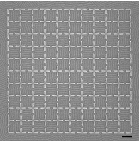
SEM image of a 10 by 10 array of square confinements with four openings. 51
SCFT simulations showing the evolution of the polymer self-assembled pattern. 52
SCFT simulations showing the density distribution of block A for different wetting conditions w-. 53
SEM images of rectangular confinements with a horizontal opening. 54
Fabrication of binary state arrays. 55
Figure 3.8 Figure 3.9 Figure 3.10
Chapter 4
Figure 4.1 Figure 4.2 Figure 4.3 Figure 4.4 Figure 4.5 Figure 4.6 Figure 4.7 Figure 4.8Chapter 5
Figure 5.1 Figure 5.2 Figure 5.3 Figure 5.4 Figure 5.5 Figure 5.6 Figure 5.7 Figure 5.8 Figure 5.9Chapter 6
Figure 6.1 Figure 6.2 Figure 6.3 Figure 6.4 Figure 6.5 Figure 6.6 Figure 6.7 Figure 6.8 Figure 6.9Chapter 7
Figure 7.1 Figure 7.2SEM images of two horizontally adjacent square confinements with an opening
placed in between. 57
SEM images of block copolymer morphology at the opening. 58
Proposed design for a four-input majority gate. 59
Diagram of a square Ising lattice. 68
Comparison of block copolymer morphologies and Ising states. 68
Ising lattice design in DSA of block copolymers. 70
Sample block copolymer pattern and its associated binary state array. 71
SEM image of a block copolymer pattern formed on the post lattice template. 72
Sample configurations where the four nearest neighbors have three +1 states and one −1 state. 74
The minimum Hamiltonian configuration when the four nearest neighbors have (a,f,k) four, (b,g,l) three, (c,h,m) two, (d,i,n) one, and (e,j,o) zero +1 states. 75
Diagrams showing the Ising lattice in the post lattice template with double posts. 76
Flowchart of the simulated annealing algorithm implemented in this chapter. 84
Effect of increasing n on the final minimum Hamiltonian configuration. 86
Effect of increasing α on the final minimum Hamiltonian configuration. 86
Comparison between a sample pattern resulting from the Ising model simulations and from DSA of block copolymers. 87
Ising model simulation results for the four template design rules. 88
Ising model simulation results for the second template design rule. 89
Ising model simulation results for the fourth template design rule. 90
Ising model simulation results for the first complex pattern. 91
Ising model simulation results for the second complex pattern. 92
Block copolymer morphology inside a double post boundary for designing a buffer and inverter. 98
Design for a buffer and inverter. 99
SEM images of the block copolymer pattern formed inside a buffer. 100
Design for a wire (cascaded buffer). 101
Design for a one-input two-output fan-out gate. 101
Design for a three-input majority gate. 102
Design for an AND gate. 104
Design for a three-input OR gate. 104
Diagrams of different Ising lattice setups. 106
Schematic illustration of the proposed fabrication process to reduce cost and increase throughput. 114 Schematic illustration of the laser zone annealing process for achieving
Figure 7.3
Appendix
Figure A.1
Design for a buffer that can be used to enlarge the region containing the output state. 117
Chapter 1
Introduction
1.1 Overview
Unconventional computation is a paradigm of computation that uses natural systems, physical or biological, to process information. Using the complexity of physical systems, unconventional computing systems can efficiently solve problems that are difficult to solve with classical von Neumann architecture.[1] One such alternative architecture is based on the Ising spin system where a large number of binary states give rise to long-range correlations through strong local interactions.[2] It has been previously shown that Ising-model-based computing systems can perform universal Boolean operations[3] and solve combinatorial optimization problems.[4] In this
thesis, we use block copolymer self-assembly, a well-studied phenomenon in polymer science, to develop a new approach to computing by applying directed self-assembly (DSA) of block copolymers to implement Ising-model-based computing systems in materials.
Implementing Ising-model-based computing systems using block copolymer self-assembly is of interest not only from a computational point of view, but also from a materials point of view since block copolymers naturally act as a lithography material. By understanding the interactions between the Ising states defined using block copolymers, we can apply the Ising model to calculate the equilibrium block copolymer morphology given a specific template. Ising model simulations
can complement self-consistent field theory (SCFT) simulations to assist rule-based and inverse template design.
This thesis investigates block-copolymer-based computation using arrays of square confinements and arrays of square lattice posts to define a two-state system. Chapter 1 introduces the basics of block copolymer DSA and the concept of unconventional computation. Chapter 2 and Chapter 3 focus on DSA of block copolymer thin films within templates of different polygonal shapes. Chapter 4, Chapter 5, and Chapter 6 focus on Ising lattice design in block copolymer DSA, Ising-model-based simulation, and Ising-model-based computation. Chapter 7 suggests ideas for future work.
1.2 Block copolymer directed self-assembly
Block copolymers are self-assembling macromolecules composed of two distinct repeating monomer units that are connected to each other by a covalent bond. Since the two blocks are chemically immiscible, but are covalently bonded together at the same time, block copolymers microphase separate into periodic arrays of microdomains upon annealing. For thin film applications, one of the blocks is used for pattern transfer while the other block is removed after the self-assembly process is completed. For example, the block copolymer used in this thesis is poly(styrene-block-dimethylsiloxane) (PS-b-PDMS). Here, the PDMS block has high etch resistance due to its silica backbone whereas the PS block has low etch resistance so that it can be easily removed by performing an O2 plasma treatment.
The phase behavior of block copolymers is governed by the segregation strength χN and volume fraction of one block f, where χ is the Flory-Huggins interaction parameter describing the chemical incompatibility between the two blocks and N is the degree of polymerization.[5]
morphologies including hexagonal arrays of spheres, parallel in-plane or out-of-plane cylinders, gyroid, and parallel in-plane or out-of-plane lamellae, where the equilibrium periodicity L0 (~
χ1/6N2/3) and feature size are on the order of the size of the macromolecules.[6] Figure 1.1 shows
the bulk morphologies and phase diagrams for block copolymers. Due to their ability to form periodic and complex nanostructures, block copolymers have been used in high-resolution lithography to fabricate field-effect transistors,[7-9] photovoltaic devices,[10-12] and plasmonic nanostructures.[13-15] However, achieving block copolymer patterns with low defect density and
good long-range order has been a challenge.
Figure 1.1 Schematic diagram showing diverse bulk morphologies and phase diagrams of block
copolymers.[5] χN is the segregation strength and fA is the volume fraction of block A. (a)
Equilibrium block copolymer morphologies: spheres (S), cylinders (C), gyroid (G), and lamellae (L). (b) A theoretical phase diagram calculated by SCFT. Close-packed sphere (CPS) morphology is also predicted. (c) An experimental phase diagram of poly(isoprene-block-styrene) (PIP-b-PS). Perforated lamellae (PL) morphology is also observed. Redrawn from reference 5.
To provide pattern registration, reduce defectivity, and improve long-range order, topographic[16-19] or chemical[20-24] templates have been commonly used to guide the self-assembly
of block copolymers. In graphoepitaxy, topographic features are patterned by conventional lithography methods and chemically functionalized to be attractive to one block. In chemoepitaxy, regions of the substrate are chemically patterned to be preferential to one block. Structural frustration and interfacial interactions induced by the template guide the self-assembly of block copolymers. Pattern registration and density multiplication have been demonstrated using both templating strategies. Figure 1.2 shows examples of complex patterns self-assembled by graphoepitaxy of PS-b-PDMS. In this thesis, we focus on the graphoepitaxy of a cylindrical morphology PS-b-PDMS using polygonal confinement and post lattice templates.
Figure 1.2 Examples of ordered block copolymer patterns using graphoepitaxy of PS-b-PDMS.
(a) Hexagonal array of self-assembled spheres.[25] (b) Nested-elbow structures with a center cross-point junction.[18] (c) Hexagonal symmetry nanohole array using a sacrificial template.[26] (d) Three-dimensional bilayer mesh structure.[27] Scale bars, 100 nm. Figures were redrawn from references.
1.3 Block copolymer as a material for computation
Unconventional computation is a model of computation that uses novel information tokens to perform computation. Unlike traditional silicon-based computers which electronically implement
computation. A key advantage of unconventional computers is their ability to efficiently solve problems that are difficult to solve classically. For a number of applications, the material properties of the physical system may be utilized for efficient computation. For example, Reyes et al. have demonstrated an analog computing approach for solving a wide class of shortest path problems by using glow discharge inside microfluidic channel systems to explore potential pathway choices in parallel.[28] In another example, deoxyribonucleic acid (DNA) has been used to solve the directed Hamiltonian path problem by trying all possible paths via polymerase chain reactions and agarose gel electrophoresis separations.[29]
Over recent decades, the scientific and engineering community has been pioneering new and unconventional approaches to computing based on novel architectures such as quantum computing,[30-32] and novel information tokens such as photons,[33-35] materials,[36-39] DNA molecules,[40-45] and even biological organisms.[46-49] Figure 1.3 shows examples of such
unconventional computing systems. In these examples, Boolean logic gates have been built and combinatorial optimization problems such as the travelling salesman problem have been solved using physical systems.
One approach to designing a novel unconventional computing systems is to create Ising machines based on the well-known spin-spin system. Ising machines are physical systems capable of finding the ground states of Ising lattices. It has been previously shown that ground states of Ising lattices can encode universal computation,[3] and solving for the ground states of Ising lattices can map to various useful combinatorial optimization problems.[4] As such, Ising machines may be enlisted to serve as an efficient coprocessor for conventional computers faced with particularly challenging computational tasks.
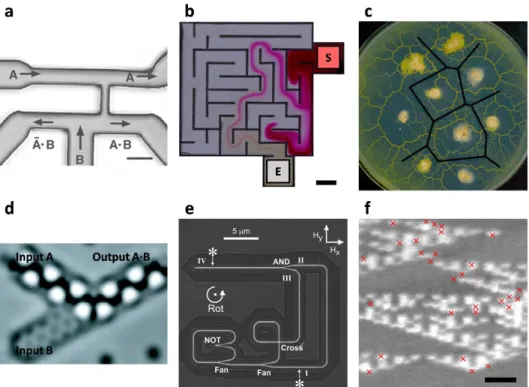
Figure 1.3 Examples of unconventional computing systems. (a) Microfluidic bubble AND/OR
gate.[50] Scale bar, 100 μm. (b) Maze solving using the Marangoni flow generated by the pH
gradient in a channel network.[51] Scale bar, 2 mm. (c) Voronoi diagram approximated by a slime
mould physarum polycephalum.[48] (d) AND gate implemented using carbon monoxide molecules
arranged on a copper (111) surface.[39] (e) Magnetic nanowire loop containing a NOT gate,
fan-out junction, and cross-over junction.[37] (f) Algorithmic self-assembly of DNA Sierpinski
triangles.[44] Scale bar, 50 nm. Figures were redrawn from references.
Recent research has focused intensively on demonstrating these Ising machines, and some have been successful in building, for example, classical Ising machines using optical parametric oscillators[52-54] and CMOS circuits,[55,56] and quantum Ising machines using qubits.[57,58] In this thesis, we develop a classical Ising-model-based computing system by using a totally new high-density approach—self-assembling block copolymers. During the self-assembly process, block copolymers arrange themselves into a minimum free energy configuration given the boundary conditions defined by the guiding templates. In essence, block copolymers are finding a solution
to an energy optimization problem through self-assembly. Ising-model-based computing can thus be implemented with block copolymers.
In addition to solving interesting and useful computation problems, block-copolymer-based computing systems may enable energy-efficient computing. Block copolymers find their ground-state configuration with minimal required energy input. With sufficient annealing time available, arbitrarily low energy consumption is possible. Using the Ising lattice presented in this thesis, an Ising state occupies at most a volume of 𝐿30/2 with a monolayer of PS-b-PDMS (as-spun film thickness ≤ L0). Assuming PS-b-PDMS has similar specific heat capacity and density as the
majority PS block and the sample is thermally annealed at 150°C, we can estimate the upper bound for the energy cost of annealing an Ising state to be in the order of 10−15 J. The energy cost of a few fJ per operation is already comparable to gate dissipation in digital logic.[59-61] This energy can be provided in the form of waste heat, harvested during cooling of conventional industrial processes (e.g. as cooling components in power plants), and further optimized by controlling annealing times and materials. Indeed, annealing-based architectures can trade-off computing speed and energy costs so that with appropriate materials science and engineering, the energy costs of a self-assembly-based approach to computing could be made arbitrarily small.
Moreover, from a material science perspective, we may be able to study properties of block copolymers by implementing a block-copolymer-based computing system. Many physical systems consist of a large number of simple components. For instance, a block copolymer film spin coated onto a 12-inch silicon wafer contains approximately 1014 Ising states with nearest-neighbor interactions. By investigating the local interactions between the simple components and studying the resulting complex emergent behavior, we can better understand the self-assembly process. Results from the thesis will have applications in block copolymer pattern prediction as well as
template design. Block-copolymer-based computing systems may even be able to simulate material science, such as phase transition behaviors of block copolymers.
Finally, we expect that the techniques used in this thesis can be extended to other materials. In designing the Ising lattice setup for block copolymers, we did not rely on the specific properties of the self-assembling material other than the antiferromagnetic nearest-neighbor interactions. Therefore, the same designing principles could be applied to different self-assembling materials such as charged colloidal particles or DNA. Ultimately, results of our work will impact fields beyond unconventional computation. For example, a sensing platform could be built by positioning nanoparticles inside the post lattice template which can dynamically change the input bits in the presence of specific chemical or biomolecules. Furthermore, a computing system could perhaps be designed using charged colloidal particles that can dynamically reset their charges subject to the pH of the solution.[62]
References
1. J. Jones, A. Adamatzky, Nat. Comput. 2014, 13, 1. 2. E. Ising, Z. Phys. 1925, 31.
3. M. Gu, A. Perales, Phys. Rev. E 2012, 86, 1. 4. F. Barahona, J. Phys. A: Math. Gen. 1982, 15, 10. 5. F. S. Bates, G. H. Fredrickson, Phys. Today 1999, 52, 2. 6. A. N. Semenov, Zh. Eksp. Teor. Fiz. 1985, 88, 4.
7. J. G. Son, M. Son, K.-J. Moon, B. H. Lee, J.-M. Myoung, M. S. Strano, M.-H. Ham, C. A. Ross, Adv. Mater. 2013, 25, 34.
8. H. Tsai, J. W. Pitera, H. Miyazoe, S. Bangsaruntip, S. U. Engelmann, C.-C. Liu, J. Y. Cheng, J. J. Bucchignano, D. P. Klaus, E. A. Joseph, D. P. Sanders, M. E. Colburn, M. A. Guillorn, ACS Nano 2014, 8, 5.
9. A. Nourbakhsh, A. Zubair, R. N. Sajjad, A. Tavakkoli K. G., W. Chen, S. Fang, X. Ling, J. Kong, M. S. Dresselhaus, E. Kaxiras, K. K. Berggren, D. Antoniadis, T. Palacios, Nano
Lett. 2016, 16, 12.
10. S. M. Lindner, S. Hüttner, A. Chiche, M. Thelakkat, G. Krausch, Angew. Chem. Int. Ed.
2006, 45, 20.
11. S. B. Darling, Energy Environ. Sci. 2009, 2.
12. C. Guo, Y.-H. Lin, M. D. Witman, K. A. Smith, C. Wang, A. Hexemer, J. Strzalka, E. D. Gomez, R. Verduzco, Nano Lett. 2013, 13, 6.
13. C. Hägglund, G. Zeltzer, R. Ruiz, I. Thomann, H.-B.-R. Lee, M. L. Brongersma, S. F. Bent,
Nano Lett. 2013, 13, 7.
14. S. K. Cha, J. H. Mun, T. Chang, S. Y. Kim, J. Y. Kim, H. M. Jin, J. Y. Lee, J. Shin, K. H. Kim, S. O. Kim, ACS Nano 2015, 9, 5.
15. P. A. Mistark, S. Park, S. E. Yalcin, D. H. Lee, O. Yavuzcetin, M. T. Tuominen, T. P. Russell, M. Achermann, ACS Nano 2009, 3, 12.
16. C. T. Black, O. Bezencenet, IEEE Trans. Nanotechnol. 2004, 3, 3. 17. T. Yamaguchi, H. Yamaguchi, Adv. Mater. 2008, 20, 9.
18. J. K. W. Yang, Y. S. Jung, J.-B. Chang, R. A. Mickiewicz, A. Alexander-Katz, C. A. Ross, K. K. Berggren, Nat. Nanotechnol. 2010, 5.
19. J.-B. Chang, H. K. Choi, A. F. Hannon, A. Alexander-Katz, C. A. Ross, K. K. Berggren,
Nat. Commun. 2014, 5, 3305.
20. M. P. Stoykovich, M. Müller, S. O. Kim, H. H. Solak, E. W. Edwards, J. J. de Pablo, P. F. Nealey, Science 2005, 308, 5727.
21. G. M. Wilmes, D. A. Durkee, N. P. Balsara, J. A. Liddle, Macromolecules 2006, 39, 7. 22. M. P. Stoykovich, H. Kang, K. C. Daoulas, G. Liu, C.-C. Liu, J. J. de Pablo, M. Müller, P.
F. Nealey, ACS Nano 2007, 1, 3.
23. J. Y. Cheng, C. T. Rettner, D. P. Sanders, H.-C. Kim, W. D. Hinsberg, Adv. Mater. 2008, 20, 16.
24. G. Liu, C. S. Thomas, G. S. W. Craig, P. F. Nealey, Adv. Funct. Mater. 2010, 20, 8. 25. I. Bita, J. K. W. Yang, Y. Jung, C. A. Ross, E. L. Thomas, K. K. Berggren, Science 2008
321, 5891.
26. A. Tavakkoli K. G., S. M. Nicaise, A. F. Hannon, K. W. Gotrik, A. Alexander-Katz, C. A. Ross, K. K. Berggren, Small 2014, 10, 3.
27. A. Tavakkoli K. G., K. W. Gotrik, A. F. Hannon, A. Alexander-Katz, C. A. Ross, K. K. Berggren, Science 2012, 336, 6086.
28. D. R. Reyes, M. M. Ghanem, G. M. Whitesides, A. Manz, Lab Chip 2002, 2, 2. 29. L. M. Adelman, Science 1994, 266, 5187.
30. D. G. Cory, A. F. Fahmy, T. F. Havel, Proc. Natl. Acad. Sci. U.S.A. 1997, 94, 5.
31. R. Vrijen, E. Yablonovitch, K. Wang, H. W. Jiang, A. Balandin, V. Roychowdhury, T. Mor, D. DiVincenzo, Phys. Rev. A 2000, 62, 1.
32. M. N. Leuenberger, D. Loss, Nature 2001, 410. 33. H. J. Caulfield, S. Dolev, Nat. Photonics 2010, 4.
34. M. Asghari, A. V. Krishnamoorthy, Nat. Photonics 2011, 5.
35. L. Larger, M. C. Soriano, D. Brunner, L. Appeltant, J. M. Gutierrez, L. Pesquera, C. R. Mirasso, I. Fischer, Opt. Express 2012, 20, 3.
36. D. A. Allwood, G. Xiong, M. D. Cooke, C. C. Faulkner, D. Atkinson, N. Vernier, R. P. Cowburn, Science 2002, 296, 5575.
37. D. A. Allwood, G. Xiong, C. C. Faulkner, D. Atkinson, D. Petit, R. P. Cowburn, Science
2005, 309, 5741.
38. A. Imre, G. Csaba, L. Ji, A. Orlov, G. H. Bernstein, W. Porod, Science 2006, 311, 5758. 39. A. J. Heinrich, C. P. Lutz, J. A. Gupta, D. M. Eigler, Science 2002, 298, 5597.
40. R. J. Lipton, Science 1995, 268, 5210.
41. Q. Ouyang, P. D. Kaplan, S. Liu, A. Libchaber, Science 1997, 278, 5337.
42. Q. Liu, L. Wang, A. G. Frutos, A. E. Condon, R. M. Corn, L. M. Smith, Nature 2000, 403. 43. T. Head, G. Rozenberg, R. S. Bladergroen, C. K. D. Breek, P. H. M. Lommerse, H. P.
Spaink, BioSystems 2000, 57, 2.
44. P. W. K. Rothemund, N. Papadakis, E. Winfree, PLoS Biol. 2004, 2, 12.
45. J. Elbaz, O. Lioubashevski, F. Wang, F. Remacle, R. D. Levine, I. Willner, Nat.
Nanotechnol. 2010, 5.
46. M. Dorigo, L. M. Gambardella, IEEE Trans. Evol. Comput. 1997, 1, 1. 47. S. Tsuda, M. Aono, Y.-P. Gunji, BioSystems 2004, 73, 1.
48. A. Adamatzky, Philos. Trans. Royal Soc. A 2015, 373, 2046. 49. R. Mayne, A. Adamatzky, PLoS One 2015, 10, 10.
50. M. Prakash, N. Gershenfeld, Science 2007, 315, 5813.
51. K. Suzuno, D. Ueyama, M. Branicki, R. Tóth, A. Braun, I. Lagzi, Langmuir 2014, 30, 31. 52. Z. Wang, A. Marandi, K. Wen, R. L. Byer, Y. Yamamoto, Phys. Rev. A 2013, 88, 6. 53. A. Marandi, Z. Wang, K. Takata, R. L. Byer, Y. Yamamoto, Nat. Photonics 2014, 8. 54. T. Inagaki, K. Inaba, R. Hamerly, K. Inoue, Y. Yamamoto, H. Takesue, Nat. Photonics
2016, 10.
55. M. Yamaoka, C. Yoshimura, M. Hayashi, T. Okuyama, H. Aoki, H. Mizuno, Hitachi
Review 2015, 64, 8.
56. M. Yamaoka, C. Yoshimura, M. Hayashi, T. Okuyama, H. Aoki, H. Mizuno, IEEE J.
Solid-State Circuits 2016, 51, 1.
57. T. F. Rønnow, Z. Wang, J. Job, S. Boixo, S. V. Isakov, D. Wecker, J. M. Martinis, D. A. Lidar, M. Troyer, Science 2014, 345, 6195.
58. B. Heim, T. F. Rønnow, S. V. Isakov, M. Troyer, Science 2015, 348, 6231. 59. B.-D. Yang, L.-S. Kim, IEEE J. Solid-State Circuits 2005, 40, 8.
60. B. Murmann, IEEE Micro 2006, 26, 2.
62. F. Reincke, W. K. Kegel, H. Zhang, M. Nolte, D. Wang, D. Vanmaekelbergh, H. Möhwald,
Chapter 2
Directed self-assembly of a two-state
block copolymer system
In this chapter, we study directed self-assembly of block copolymer thin films within templates of different polygonal shapes. Ladder-shaped block copolymer structures consisting of parallel bars, bends, and T-junctions are formed inside square confinement. We define binary states by the two degenerate alignment orientations, and study properties of the two-state system such as distribution of the states, nearest-neighbor correlation, and defect tolerance. We control the binary states by changing the confinement geometry or placing lithographic guiding patterns inside the confinement. The resulting block copolymer patterns could potentially act as a physical read-only memory in addition to functioning as a lithography mask.
2.1 Introduction
Block copolymer self-assembly in thin films can spontaneously generate periodic nanoscale patterns such as hexagonal arrays of dots or parallel lines, which have been proposed for applications such as nanoporous filtration membranes,[1,2] plasmonic structures,[3,4] integrated circuit fabrication,[5-7] and magnetic storage media.[8-10] Many of these applications require the nanoscale features to have long-range order or to form specific non-periodic structures with low
defect density. Directed self-assembly (DSA) addresses these issues by using graphoepitaxial[11-14] and/or chemoepitaxial[15-19] templates, fabricated by conventional lithography techniques, to guide
the self-assembly of thin films of block copolymers. Various microelectronic device-oriented features such as concentric rings, bends, jogs, terminations, and T-junctions have been made, and these patterns have subsequently been transferred into functional materials to fabricate structures such as metal nanowire ring arrays[20-22] or parallel fins for field-effect transistors.[7,23,24]
Common templates used for DSA include one-dimensional features (trenches or chemical stripe patterns), or two-dimensional features (pits or chemically patterned regions). Although the templating effect from trench confinement has been well studied,[25-27] two-dimensional templates provide a wider set of geometries to guide block copolymer self-assembly, and can lead to formation of multiple degenerate structures. For example, concentric ring structures have been self-assembled inside symmetric confinements,[20,21] and we recently demonstrated nanoscale
Archimedean spirals with specific chirality formed inside circular pits.[28] By studying such block copolymer systems that have energetic degeneracy, graphoepitaxial pattern control inside two-dimensional templates can be better understood. Moreover, by assigning different states or bits to the two degenerate morphologies, the resulting block copolymer patterns could act as a physical read-only memory.
This chapter describes DSA of block copolymer films within templates of different polygonal shapes. In square templates, two degenerate morphologies can form, and the presence of asymmetry inside the templates breaks the degeneracy. We describe the properties of the binary states including distribution, correlation, and defect tolerance, and present methods for controlling the binary state orientations.
2.2 Experimental methods
To control the self-assembly in block copolymer thin films, we used electron-beam lithography to fabricate templates of different polygonal shapes, and solvent annealing to facilitate the block copolymer self-assembly process. In this section, we describe the experimental methods for template fabrication, block copolymer self-assembly, reactive-ion etching, and metrology.
2.2.1 Template fabrication
The topographic templates were fabricated using electron-beam lithography with a hydrogen silsesquioxane (HSQ) resist. A silicon substrate was spin coated with 42-nm-thick HSQ film (XR-1541 2% solids, Dow Corning). The thickness was determined by ellipsometry. A Raith 150 electron-beam lithography system operated at 30 kV acceleration voltage was used to expose topographic features with various geometries. After exposure, the samples were developed in a 24°C high contrast salty developer (1% NaOH and 4% NaCl in de-ionized water)for 4 min, rinsed in de-ionized water for 3 min, and blow dried with N2 gas.[29] Template dimensions were inspected
by scanning electron microscope (SEM) imaging. Templates for 16 kg/mol poly(styrene-block-dimethylsiloxane) (PS-b-PDMS) were fabricated using 30-nm-thick HSQ film.
2.2.2 Block copolymer self-assembly
To make the templates attractive to the majority PS block, the templates were chemically functionalized with a PS brush (11 kg/mol, Polymer Source Inc.) by spin coating 1% brush solution in propylene glycol monomethyl ether acetate (PGMEA) and annealing the samples in a vacuum oven at 170°C for 14 h. The samples were rinsed with toluene for 1 min after annealing to remove excess PS brush. The resulting thickness of the PS brush bonded to the substrate was 5 nm. Next,
2% PS-b-PDMS (Mw = 45.5 kg/mol, fPDMS = 32%, PDI = 1.08, Polymer Source Inc.) solution in
PGMEA was spin coated onto the templated substrate. The resulting film thickness was 27 nm. The samples were solvent annealed using a 5:1 mixture of toluene and heptane at room temperature for 5 h. We placed the samples on a glass slide stack (0.8 cm in height) inside a crystallization dish (1.5 cm in height, 5 cm in diameter) and added 1.5 ml of the 5:1 toluene and heptane mixture. The chamber was covered with a petri dish (10 cm in diameter). During the 5 h annealing, leakage of solvent vapor occurred at a rate of 585 µg/min. 16 kg/mol PS-b-PDMS (fPDMS = 31%, PDI = 1.08,
Polymer Source Inc.) was spin coated to a thickness of 25 nm and thermally annealed in a vacuum oven at 150°C for 14 h.
2.2.3 Reactive-ion etching
Reactive-ion etching of the annealed block copolymer film was performed in two steps. First, the top PDMS wetting layer was removed using a 5 s CF4 plasma treatment with a power of 50 W and
pressure of 15 mTorr. Next, the PS matrix was removed using a 22 s O2 plasma treatment with a
power of 90 W and pressure of 6 mTorr. This step also oxidized the PDMS cylinders. For 16 kg/mol PS-b-PDMS, the CF4 plasma was applied for 3 s and O2 plasma was applied for 12 s.
2.2.4 Metrology
Metrology was performed by examining the HSQ templates and the reactive-ion etched block copolymer films using a SEM. Top down SEM images were obtained using a Raith 150 SEM operated at 10 kV acceleration voltage and 6 mm working distance, and Zeiss Sigma SEM operated at 3 kV acceleration voltage and 4 mm working distance.
2.3 Results and discussion
In this section, we describe our approach for defining the basis states inside lithographic confinement, and discuss different methods for controlling the binary states.
2.3.1 Defining the basis states inside lithographic confinement
We first demonstrate the morphologies of a block copolymer film within polygonal templates. The block copolymer is a 45.5 kg/mol cylindrical morphology PS-b-PDMS (SD45). Thin films of SD45 microphase separate into a layer of PDMS cylinders with in-plane orientation surrounded by a PS matrix, and a wetting layer of PDMS at the air interface. Electron-beam lithography was performed using an HSQ resist on silicon substrates to fabricate topographic features of various geometries. The topographic templates were chemically functionalized with a hydroxyl-terminated PS brush. SD45 block copolymer was spin coated onto the substrate to a thickness of 27 nm, solvent annealed in a vapor of toluene and heptane, and reactive-ion etched to reveal a pattern consisting of oxidized PDMS cylinders.
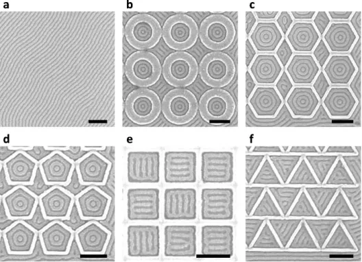
Figure 2.1 shows an example of oxidized PDMS patterns without any template (Figure 2.1a) and within polygonal confinement (Figures 2.1b-2.1f). On an untemplated substrate, the
periodicity of the PDMS cylinders (L0) was ~36 nm. As shown in Figures 2.1b-2.1d, the PDMS
cylinders formed a one-state system of concentric rings inside circular, hexagonal, and pentagonal confinement. However, the PDMS cylinders formed a two-state system inside square confinement and a three-state system inside triangular confinement (Figure 2.1e and Figure 2.1f). For both confinements, bars parallel to one of the sides were formed inside an outer ring, creating 90° T-junctions for square confinement and 60° Y-T-junctions for triangular confinement. As the interior angle is decreased, high deformation is imposed on the microdomains at the corners,[15,17] which
is relieved by transitioning to a pattern of parallel bars instead of concentric rings. For square confinement, orientation of the parallel bars was restricted to either the horizontal or vertical direction, and these degenerate states are defined as the basis states of the system.
Figure 2.1 SEM images of untemplated and templated block copolymer patterns. The HSQ
templates were functionalized with the majority PS block. (a) Untemplated PDMS cylinders with
L0 = ~36 nm. (b) One-state system with concentric rings inside circular confinement. Radius was
2.4L0. (c) One-state system inside hexagonal confinement. Apothem was 3.5L0. (d) One-state
system inside pentagonal confinement. Apothem was 2.5L0. (e) Two-state system with degenerate
ladder-shaped structures inside square confinement. Apothem was 2.4L0. (f) Three-state system
inside triangular confinement. Apothem was 1.8L0. The radius and apothem were measured by
subtracting brush thickness from confinement dimensions. Scale bars, 200 nm.
Inside circular, hexagonal, and pentagonal confinement, we observed random formation of defective structures consisting of Archimedean spiral patterns instead of concentric rings (Figure
2.2). Choi et al. have reported experimental and simulation work on formation of the spiral
Investigation of a two-state system which uses chirality of the spiral structures as the basis states may be of interest for future research.
Figure 2.2 SEM image of block copolymer patterns formed inside pentagonal confinement. As
indicated by the red dashed lines, partial (left) and complete (right) Archimedean spiral patterns were observed at random locations. Similar spiral patterns were also observed in circular and hexagonal confinement. Scale bar, 200 nm.
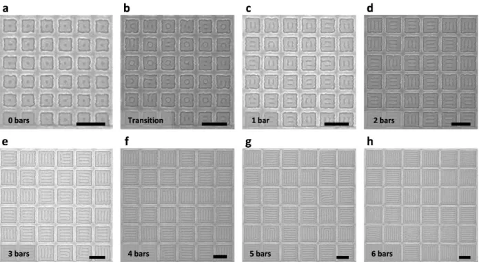
We focus our study on the square confinement since it resulted in a well-defined two-state system with 90° bends and T-junctions. Commensurability is achieved when the width of the confinement minus the brush thickness is equivalent to an integer multiple of L0. Figure 2.3 shows
the ladder-shaped block copolymer patterns formed inside square templates, with the number of parallel bars increasing with confinement dimensions. The smallest templates produced a one-state system consisting of a single ring (Figure 2.3a), then a PDMS sphere was formed inside the outer ring as the confinement dimension was increased between 2L0 and 3L0 (Figure 2.3b). In this
regime, both ladder-shaped structures (two-state system) and concentric ring structures (one-state system) were observed. With increasing dimensions the interior spheres were either horizontally or vertically connected to the outer ring resulting in a two-state system, then an additional bar was
formed inside the outer ring (Figures 2.3c-2.3h). For larger incommensurate templates, ladder-shaped structures were still produced, but the number of parallel bars varied by one from structure to structure.
Figure 2.3 SEM images of ladder-shaped block copolymer patterns inside square confinement.
Figure 2.3a and Figures 2.3c-2.3h show commensurate conditions while Figure 2.3b shows transition between a one-state system (Figure 2.3a) and a two-state system (Figure 2.3c) inside incommensurate confinement dimensions. Width of the square confinement was (a) 2.2L0, (b)
2.8L0, (c) 3.0L0, (d) 4.1L0, (e) 5.1L0, (f) 6.1L0, (g) 7.1L0, and (h) 8.1L0 (L0 = 36 nm). Depending on
the confinement width, 0 to 6 parallel bars were formed inside an outer ring. Scale bars, 200 nm.
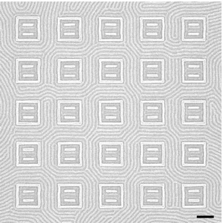
2.3.2 Properties of the two-state system
To show that the two basis states are degenerate, we created arrays of 10 by 10 square templates and measured the distribution of horizontally aligned and vertically aligned ladder-shaped structures. For simplicity, we defined horizontal alignment as the ‘0’ state and vertical alignment as the ‘1’ state. Among 600 examined structures, 51.5% were in 0 state and 48.5% were in 1 state,
forming with essentially equal probability. For a null hypothesis H0: p = 0.5 and alternative
hypothesis H1: p ≠ 0.5 where p denotes ratio of 1 state, the Z-test statistic was 0.735. The
corresponding p-value was 0.462, and we failed to reject the null hypothesis at 5% level of significance. In addition, the binary states had tolerance to defects in the sense that even with defects present the patterns could be assigned as 0 or 1 (Figure 2.4a).
Figure 2.4 SEM images of ladder-shaped block copolymer patterns inside square confinement for
measuring distribution and correlation. (a) The two binary states were equally probable in a large array of square confinements. (b) The two states were uncorrelated in pairs of adjacent square confinements. For both figures, width of the square confinement was 5.1L0, resulting in PDMS
patterns with 3 parallel bars inside an outer ring. Scale bars, 200 nm.
Next, we investigated whether the binary state of the four neighbors was correlated with the binary state of the surrounded square. For each square not positioned on the boundary of the square array, there were four adjacent squares as indicated by the red dashed line (Figure 2.4a). The normalized mean state-state correlation is
𝜌 = ∑𝑖~𝑗𝑠𝑖𝑠𝑗
where 𝑠𝑘 = +1 for 1 state, 𝑠𝑘 = −1 for 0 state, and the sum was taken over every pair of adjacent
states. The negligible value of correlation suggests that there is no nearest-neighbor influence. To investigate the correlation between isolated pairs of adjacent square confinements in samples shown in Figure 2.4b, we define nXY as the number of cases where the left binary state is
X (0 or 1) and the right binary state is Y (0 or 1). For 576 structures, the resulting counts were n00
= 144 (25.0%), n01 = 137 (23.8%), n10 = 143 (24.8%), and n11 = 149 (25.9%) with 3 (0.5%) defects.
The ϕ coefficient calculated as
𝜙 = 𝑛00𝑛11− 𝑛01𝑛10
√(𝑛00+ 𝑛01)(𝑛00+ 𝑛10)(𝑛01+ 𝑛11)(𝑛10+𝑛11)
= 0.023
was close to zero, indicating negligible association between two adjacent states in isolated pairs of square confinements. A similar set of samples made with a template wall height of 30 nm instead of 42 nm yielded ϕ = −0.03, again indicating negligible association. For wall height below 30 nm, the PDMS cylinders crossed the walls leading to poorly defined block copolymer structures within the templates.
2.3.3 Methods for controlling the binary states
Having established the non-interacting binary-state system described above, we now discuss methods to control the alignment of the states. A simple method for controlling the orientation of the binary states is by changing the confinement to a rectangular shape. Figure 2.5 shows ladder-shaped block copolymer patterns formed inside rectangular confinements with an aspect ratio of 2:1. Similar to the square confinement, we were able to accurately control the number of parallel bars using confinement dimensions. When the vertical confinement width was commensurate with
integer. However, we observed only 0 state at these conditions.
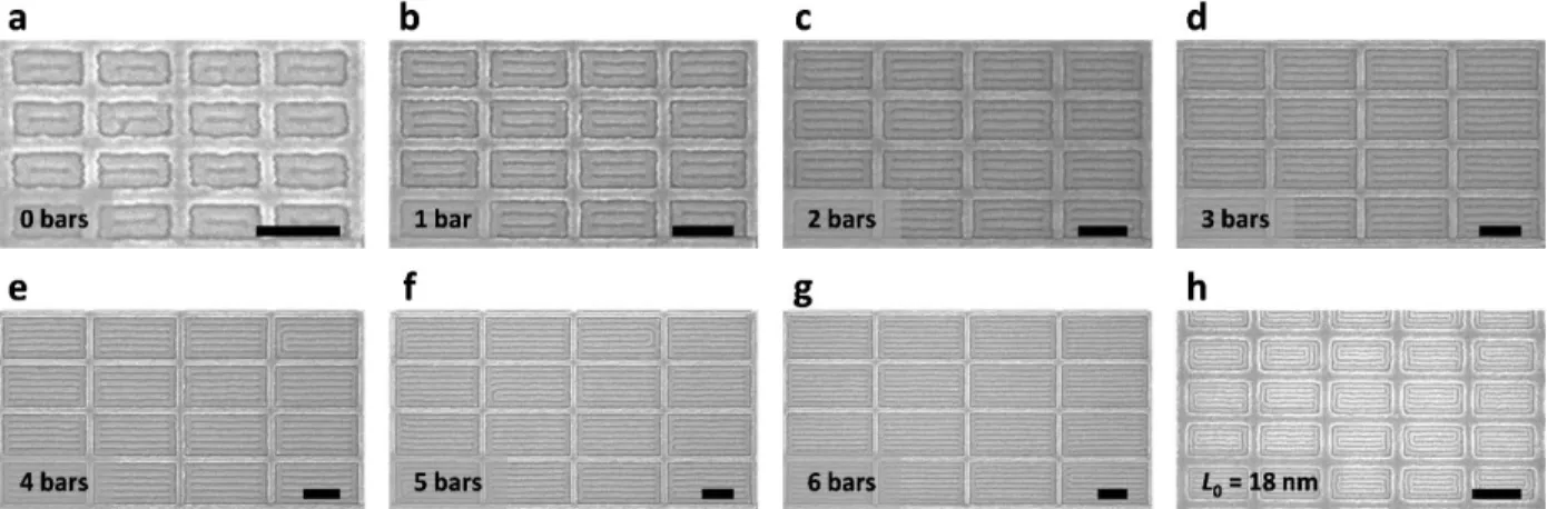
Figure 2.5 SEM images of aligned ladder-shaped block copolymer patterns inside rectangular
confinement. Aspect ratio was 2:1. Vertical width of the rectangular confinement was (a) 2.0L0,
(b) 3.1L0, (c) 4.1L0, (d) 5.1L0, (e) 6.1L0, (f) 7.0L0, and (g) 7.9L0 for SD45 (L0 = 36 nm). For Figure
2.5h, 16 kg/mol PS-b-PDMS with L0 = 18 nm was used. Parallel bars were formed in the horizontal
direction (0 state) to minimize the number of T-junctions. Scale bars, 200 nm.
Figure 2.6 Illustration of horizontally (left) and vertically (right) aligned ladder-shaped structure
inside rectangular confinement with confinement dimensions equal to 2nL0 and nL0 (n is an
integer). Only parts of the ladder-shaped structure that are parallel to the alignment orientation are shown. When n = 4, four T-junctions are formed inside a horizontally aligned ladder-shaped structure, whereas twelve T-junctions are formed inside a vertically aligned ladder-shaped structure. To minimize the number of T-junctions, alignment orientation parallel to the longer sidewall is favored.
horizontal and vertical alignment. When the horizontal and vertical confinement widths are equal to 2nL0 and nL0, respectively, a ladder-shaped structure in the 0 state results in 2n − 4 T-junctions
(n is an integer). On the other hand, a ladder-shaped structure in the 1 state results in 4n − 4 T-junctions. Since T-junctions are energetically unfavorable,[30-32] the 0 state was favored over the 1 state to minimize the number of T-junctions. The preferential alignment can also be understood as the longer sidewall having a stronger templating effect compared to the shorter sidewall, analogous to the perpendicular orientation of lamellar morphology PS-b-PDMS observed within deep trenches functionalized with a preferential sidewall brush and a neutral bottom surface.[33]
In Figure 2.7, the horizontal and vertical dimensions of the confinement were approximately commensurate, 4.1L0 and 2.9L0, respectively, and the structure formed two
T-junctions instead of four T-T-junctions. Non-integer aspect ratios in which only the shorter dimension satisfies the commensurability condition can also be used to further promote alignment
(Figure 2.7b). As the aspect ratio increases, the confinement approximates a trench leading to
well-ordered microdomains parallel to the sidewalls.
Figure 2.7 SEM images of aligned ladder-shaped block copolymer patterns inside rectangular
confinement with a non-integer aspect ratio (AR). Vertical width of the rectangular confinement was (a) 2.9L0 and (b) 4.1L0, approximately commensurate with the equilibrium periodicity.
Horizontal width of the confinement was (a) 4.1L0 and (b) 6.6L0. Aspect ratio was (a) 1.4:1 and
This approach was extended to fabricate aligned T-junctions with sub-10-nm spacing using a 16 kg/mol cylindrical morphology PS-b-PDMS with L0 = 18 nm, thermally annealed on a
functionalized patterned substrate. As shown in Figure 2.5h, sub-10-nm half-pitch ladder-shaped structures were formed inside rectangular confinement with the microdomains primarily parallel to the longer side. Unlike SD45, the ladder-shaped structures were influenced by the curvature of the corners of the template due to the smaller L0, and a complete ring was formed between the
confinement and the ladder-shaped structure.
Preferential alignment is observed in non-rectangular geometries such as trapezoids and isosceles triangles, as shown in Figure 2.8. For trapezoidal confinement, T-junctions formed with desired bending angles because the microdomains aligned parallel to the longer side. Isosceles triangles typically showed preferential alignment parallel to either of the two longer sides. This produced two junctions whereas alignment parallel to the shorter side resulted in four T-junctions. Thus the confinement geometry determines the number of states, i.e. a three-state system in equilateral triangles (Figure 2.1f), a two-state system in acute isosceles triangles or possibly a one-state system in obtuse isosceles triangles.
Figure 2.8 SEM images of aligned ladder-shaped block copolymer patterns inside trapezoidal
(red) and isosceles triangular (blue) confinement. The ladder-shaped structures were typically aligned parallel to the longer side to minimize T-junction formations. Vertical width of the confinement was 5.8L0. Scale bar, 200 nm.
An alternative method for controlling the orientation of the binary states is by placing lithographically defined guiding patterns inside the confinement. The effect of posts, dashes, or walls has been previously studied in detail.[13,14,34] Figure 2.9 shows square confinements, each with two horizontal HSQ walls where the walls were positioned a distance L0 away from the edges.
Because two PDMS bars in the ladder-shaped block copolymer structures were replaced with the horizontal HSQ walls functionalized with the majority PS block, all block copolymer patterns were also horizontally aligned and set to the 0 state.
Figure 2.9 SEM image of aligned ladder-shaped block copolymer patterns inside square
confinement with horizontal guiding patterns. Without the guiding patterns, ladder-shaped structures with four horizontally or vertically aligned PDMS bars were formed with equal probability. However, by placing functionalized HSQ walls where the PDMS bars should form, alignment orientation was controlled. Scale bar, 200 nm.
2.4 Conclusion
The self-assembly of block copolymers inside discrete and interacting polygonal templates is investigated. Square and triangular confinement with dimensions of a few L0 produced
ladder-shaped structures instead of the concentric rings seen in smaller confinements or in circular pits. In square confinement, the two degenerate orientations of the ladder-shaped structures could be considered as independently controlled binary states with tolerance to defects. The binary states were selected by either changing the confinement aspect ratio or placing additional lithographic features inside the confinement. The resulting line segments, bends, and T-junctions composing the ladder-shaped structures may be useful as circuit-relevant geometries or binary information storage. Although the multi-state composite structures used in our work are less than 1 μm in dimension, we expect larger sizes to yield similar result. If the binary states could be read out optically or electrically in a very large array, the block copolymer patterns could be used to physically store information. In the next chapter, we use the two-state system designed in this chapter and place openings on the square confinement walls to allow neighboring states to be connected. We investigate the effect of wall openings on the two-state system.
References
1. H. Uehara, M. Kakiage, M. Sekiya, D. Sakuma, T. Yamonobe, N. Takano, A. Barraud, E. Meurville, P. Ryser, ACS Nano 2009, 3, 4.
2. W. A. Phillip, B. O’Neill, M. Rodwogin, M. A. Hillmyer, E. L. Cussler, ACS Appl. Mater.
Interfaces 2010, 2, 3.
3. C. Hägglund, G. Zeltzer, R. Ruiz, I. Thomann, H.-B.-R. Lee, M. L. Brongersma, S. F. Bent,
Nano Lett. 2013, 13, 7.
4. S. K. Cha, J. H. Mun, T. Chang, S. Y. Kim, J. Y. Kim, H. M. Jin, J. Y. Lee, J. Shin, K. H. Kim, S. O. Kim, ACS Nano 2015, 9, 5.
5. H. Yi, X.-Y. Bao, J. Zhang, C. Bencher, L.-W. Chang, X. Chen, R. Tiberio, J. Conway, H. Dai, Y. Chen, S. Mitra, H.-S. P. Wong, Adv. Mater. 2012, 24, 23.
6. H. Yi, X.-Y. Bao, R. Tiberio, H.-S. P. Wong, Nano Lett. 2015, 15, 2.
7. H. Tsai, J. W. Pitera, H. Miyazoe, S. Bangsaruntip, S. U. Engelmann, C.-C. Liu, J. Y. Cheng, J. J. Bucchignano, D. P. Klaus, E. A. Joseph, D. P. Sanders, M. E. Colburn, M. A. Guillorn, ACS Nano 2014, 8, 5.
8. X. Yang, L. Wan, S. Xiao, Y. Xu, D. K. Weller, ACS Nano 2009, 3, 7.
9. O. Hellwig, J. K. Bosworth, E. Dobisz, D. Kercher, T. Hauet, G. Zeltzer, J. D. Risner-Jamtgaard, D. Yaney, R. Ruiz, Appl. Phys. Lett. 2010, 96, 5.
10. R. Ruiz, E. Dobisz, T. R. Albrecht, ACS Nano 2011, 5, 1.
11. C. T. Black, O. Bezencenet, IEEE Trans. Nanotechnol. 2004, 3, 3. 12. T. Yamaguchi, H. Yamaguchi, Adv. Mater. 2008, 20, 9.
13. J. K. W. Yang, Y. S. Jung, J.-B. Chang, R. A. Mickiewicz, A. Alexander-Katz, C. A. Ross, K. K. Berggren, Nat. Nanotechnol. 2010, 5.
14. J.-B. Chang, H. K. Choi, A. F. Hannon, A. Alexander-Katz, C. A. Ross, K. K. Berggren,
Nat. Commun. 2014, 5, 3305.
15. G. M. Wilmes, D. A. Durkee, N. P. Balsara, J. A. Liddle, Macromolecules 2006, 39, 7. 16. J. Y. Cheng, C. T. Rettner, D. P. Sanders, H.-C. Kim, W. D. Hinsberg, Adv. Mater. 2008,
20, 16.
17. M. P. Stoykovich, M. Müller, S. O. Kim, H. H. Solak, E. W. Edwards, J. J. de Pablo, P. F. Nealey, Science 2005, 308, 5727.
18. M. P. Stoykovich, H. Kang, K. C. Daoulas, G. Liu, C.-C. Liu, J. J. de Pablo, M. Müller, P. F. Nealey, ACS Nano 2007, 1, 3.
19. G. Liu, C. S. Thomas, G. S. W. Craig, P. F. Nealey, Adv. Funct. Mater. 2010, 20, 8. 20. Y. S. Jung, W. Jung, C. A. Ross, Nano Lett. 2008, 8, 9.
21. S.-J. Jeong, J. E. Kim, H.-S. Moon, B. H. Kim, S. M. Kim, J. B. Kim, S. O. Kim, Nano
Lett. 2009, 9, 6.
22. J. Chai, D. Wang, X. Fan, J. M. Buriak, Nat. Nanotechnol. 2007, 2.
23. J. G. Son, M. Son, K.-J. Moon, B. H. Lee, J.-M. Myoung, M. S. Strano, M.-H. Ham, C. A. Ross, Adv. Mater. 2013, 25, 34.
24. A. Nourbakhsh, A. Zubair, R. N. Sajjad, A. Tavakkoli K. G., W. Chen, S. Fang, X. Ling, J. Kong, M. S. Dresselhaus, E. Kaxiras, K. K. Berggren, D. Antoniadis, T. Palacios, Nano
Lett. 2016, 16, 12.
25. Y. S. Jung, C. A. Ross, Nano Lett. 2007, 7, 7.
28. H. K. Choi, J.-B. Chang, A. F. Hannon, J. K. W. Yang, K. K. Berggren, A. Alexander-Katz, C. A. Ross, Nano Futures 2017, 1, 1.
29. J. K. W. Yang, K. K. Berggren, J. Vac. Sci. Technol. B 2007, 25, 6. 30. S. P. Gido, E. L. Thomas, Macromolecules 1994, 27, 21.
31. E. Burgaz, S. P. Gido, Macromolecules 2000, 33, 23.
32. D. Duque, K. Katsov, M. Schick, J. Chem. Phys. 2002, 117, 22.
33. W. Bai, K. Gadelrab, A. Alexander-Katz, C. A. Ross, Nano Lett. 2015, 15, 10.
Chapter 3
Nearest-neighbor interactions via
confinement wall opening
In this chapter, we study directed self-assembly of block copolymer thin films within square confinements with different number of openings placed around the confinement walls. We investigate templating effect of the wall openings on binary states defined inside the confinement. Self-consistent field theory simulations show the templating effect from the openings and reproduce the experimental results. We demonstrate scaling of a single binary state into a larger binary state array with individual binary state control. We discuss the effect of opening size variation on the nearest-neighbor interactions.
3.1 Introduction
In the previous chapter, we designed a two-state system using directed self-assembly (DSA) of block copolymer thin films within square confinements. Inside each confinement, a binary state was defined based on the two degenerate alignment orientations of the ladder-shaped structures. We measured properties of the two-state system such as distribution of the states and nearest-neighbor correlation, and demonstrated defect tolerance of the system. By studying the effect of changing the confinement geometry and placing lithographic guiding patterns inside the
confinement, we controlled the alignment orientation and formation of parallel bars, bends, and T-junctions. The resulting circuit-relevant geometries may be useful for fabrication of FinFETs.[1-8]
In addition, if the binary states could be read out optically[9-13] or electrically[13-17] in a very large array after pattern transfer, the block copolymer patterns may be used to physically store and read out information.
Having established a defect-tolerant and non-interacting two-state system, we now study the effect of placing openings on the confinement walls. An opening placed on the wall separating two adjacent states allows the two states to be physically connected to each other. Then, a block copolymer pattern formed inside one confinement may influence the block copolymer morphology inside its adjacent confinement via interactions through the opening. At the same time, the opening itself is a narrow topographic feature that may introduce a strong templating effect, thereby dominating any effect caused by the nearest-neighbor interactions. Therefore, the templating effect of the openings on the binary states must be investigated to better understand graphoepitaxial pattern control inside templates of various geometries, and to ultimately design an interacting two-state system.
This chapter describes the effect of placing different number of openings around the square confinement walls. Both experimental and self-consistent field theory (SCFT) simulation results show strong templating effect from the wall openings. Using the openings as a new method for controlling the binary state orientations, we demonstrate the propagation of a single binary state into a larger array with orientation control. Finally, we discuss the effect of opening size variation on the nearest-neighbor interactions.
3.2 Experimental methods
For template fabrication, block copolymer self-assembly, reactive-ion etching, and metrology, the same experimental methods as described in Chapter 2 were used. A 45.5 kg/mol cylindrical morphology poly(styrene-block-dimethylsiloxane) (PS-b-PDMS) was used for all experiments in this chapter.
3.3 Simulation methods
The SCFT simulations were performed in collaboration with Karim R. Gadelrab and Prof. Alfredo Alexander-Katz at MIT.
We consider a monodispersed melt of n A-B diblock copolymer of volume V, with each diblock molecule composed of N segments. The A and B blocks consist of fN and (1 − f)N chain segments, respectively. The interaction between the dissimilar blocks is controlled by a Flory-Huggins parameter χ. Within the mean-field approximation, the free energy of the system F is expressed in terms of field variables
𝐹 𝑛𝑉𝑘B𝑇=
1
𝑉∫ 𝑑𝑟(𝜒𝜙𝐴(𝑟)𝜙𝐵(𝑟) − 𝑤𝐴(𝑟)𝜙𝐴(𝑟) − 𝑤𝐵(𝑟)𝜙𝐵(𝑟) − 𝑝(𝑟)[1 − 𝜙𝐴(𝑟) − 𝜙𝐵(𝑟)]) − ln 𝑄[𝑤𝐴, 𝑤𝐵]
where ϕα(r) is the volume fraction of species α at position r. Q[wA, wB] is the partition function of
a non-interacting polymer in external fields wα(r). The polymer is assumed to be incompressible,
so the constraint ϕA(r) + ϕB(r) = 1 is enforced through a pressure field p(r). The free energy F is
compared to the thermal energy kBT.
𝑄 = 1
𝑉∫ 𝑑𝑟𝑞(𝑟, 1)
where q(r, s) is a restricted chain partition function (propagator) that could be calculated by solving a modified diffusion equation
𝜕𝑞 𝜕𝑠 = ∇ 2𝑞(𝑟, 𝑠) − 𝑤 𝐴(𝑟)𝑞(𝑟, 𝑠), 0 ≤ 𝑠 < 𝑓 𝜕𝑞 𝜕𝑠 = ∇ 2𝑞(𝑟, 𝑠) − 𝑤 𝐵(𝑟)𝑞(𝑟, 𝑠), 𝑓 ≤ 𝑠 < 1
subjected to the initial condition q(r, 0) = 1. Since the two ends of the polymer are distinct, a complementary partition function q*(r, s) is defined similarly and satisfies the same modified diffusion equation with an initial condition q(r, 1) = 1. Here, we utilize s as a chain contour variable in units of N. All lengths are expressed in units of the unperturbed radius-of-gyration of a polymer,
Rg = (Nb2/6)1/2, where b is the statistical segment length. The solution to the modified diffusion
equation is conducted following the pseudo-spectral method.[18,19] An iterative relaxation of the fields towards their saddle-point values is implemented following the method by Sides et al.[20,21]
By evaluating q(r, s) and its complementary, the segments’ volume fractions can be determined as follows 𝜙𝐴(𝑟) = 1 𝑄∫ 𝑑𝑠𝑞(𝑟, 𝑠)𝑞 ∗(𝑟, 𝑠) 𝑓 0 𝜙𝐵(𝑟) = 1 𝑄∫ 𝑑𝑠𝑞(𝑟, 𝑠)𝑞 ∗(𝑟, 𝑠) 1 𝑓
both directions. The volume fraction f and degree of incompatibility χN are chosen such that striped domains (projection of in-plane cylinders in 2D) are generated. Hence, for the purpose of this work, we chose f = 0.5 and χN = 12.
The role of the DSA of the polymer domains is depicted through a masking method. A pressure potential w+ = (wB + wA)/2 is imposed as a mask on the location of the walls to create
excluded areas for the polymer. A magnitude of w+ = 10 is applied on walls of thickness of six
pixels. To incorporate the effect of surface preferentiality towards the majority block in experiments, an exchange potential w- = (wB − wA)/2 = 3.5 is applied surrounding the walls with a
thickness of four pixels to attract block B. The confining template is displaced from the boundaries of the computational domain by 70 pixels to minimize the effect of the mirror image (periodic boundary conditions) on the polymer domains near the walls.
3.4 Results and discussion
In this section, we describe experimental and SCFT simulation results showing the templating effect from confinement wall openings, and demonstrate scaling into a larger binary state array. We discuss the effect of opening size variation on the resulting block copolymer patterns.
3.4.1 Templating effect from confinement wall openings
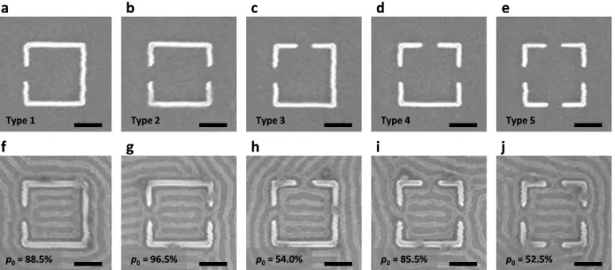
We first demonstrate that the wall openings have a strong templating effect, and the orientation of the binary states can be successfully controlled by creating different number of openings in the confinement. Figure 3.1 shows five possible types of 5L0 wide square confinements with one to
four 1L0 wide openings on the sides of the confinement. We created arrays of square confinements