HAL Id: hal-01307382
https://hal-iogs.archives-ouvertes.fr/hal-01307382
Submitted on 6 Oct 2017HAL is a multi-disciplinary open access archive for the deposit and dissemination of sci-entific research documents, whether they are pub-lished or not. The documents may come from teaching and research institutions in France or
L’archive ouverte pluridisciplinaire HAL, est destinée au dépôt et à la diffusion de documents scientifiques de niveau recherche, publiés ou non, émanant des établissements d’enseignement et de recherche français ou étrangers, des laboratoires
Hybrid Plasmonic Mode by Resonant Coupling of
Localized Plasmons to Propagating Plasmons in a
Kretschmann Configuration
Mitradeep Sarkar, Mondher Besbes, Julien Moreau, Jean-François Bryche,
Aurore Olivéro, Gregory Barbillon, Anne-Lise Coutrot, Bernard Bartenlian,
Michael Canva
To cite this version:
Mitradeep Sarkar, Mondher Besbes, Julien Moreau, Jean-François Bryche, Aurore Olivéro, et al.. Hybrid Plasmonic Mode by Resonant Coupling of Localized Plasmons to Propagating Plasmons in a Kretschmann Configuration. ACS photonics, American Chemical Society„ 2015, 2 (2), pp.237-245. �10.1021/ph500351b�. �hal-01307382�
Hybrid plasmonic mode by resonant coupling of localized
plasmons to propagating plasmons in a Kretschmann
configuration
Mitradeep Sarkar1, Mondher Besbes1, Julien Moreau1, Jean-François Bryche1,2, Aurore Olivéro1, Grégory Barbillon2, Anne-Lise Coutrot1, Bernard Bartenlian2,
Michael Canva1*
1 - Laboratoire Charles Fabry,
Institut d’Optique Graduate School, Univ Paris Sud, CNRS, 2 avenue Augustin Fresnel, 91127 Palaiseau, France
2 - Institut d'Électronique Fondamentale,
Université Paris Sud, CNRS Bât. 220, - Rue Ampère, 91405 Orsay, France
ABSTRACT. Metal nanoparticles have the ability to strongly enhance the local electromagnetic field in their vicinity. Such enhancement is crucial for biomolecular detection and is used by techniques such as surface plasmon resonance detection or surface enhanced Raman scattering. For these processes, the sensitivity strongly depends on the electromagnetic field intensity confined around such nanoparticles. In this article, we have numerically studied an array of metallic nanocylinders, which can sustain Localized Surface Plasmons (LSP). However, the excitation wavelengths of the LSP are not tunable due to their limited dispersion. We have demonstrated a plasmonic mode, the Hybrid Lattice Plasmon (HLP), which is excited in such a periodic array by adding a uniform thin metallic film below it. This mode is a result of a harmonic coupling between the propagating surface plasmons present in such a metallic film with the Bragg waves of the array. It shows a strong confinement of the electromagnetic field intensity around the nanocylinders, similar to the LSP, but the dispersion of this HLP mode is, however, similar to that of the propagating plasmons, and thus can be tuned over a wide range of excitation wavelengths. The structure was fabricated using electron beam lithography, and characterized by a surface plasmon resonance setup. These experimental results show that the HLP mode can be excited in a classical Kretschmann configuration with a dispersion similar to the prediction of numerical simulations.
KEYWORDS. Plasmonics, Nano-materials, Field enhancement, surface plasmon resonance modes, hybrid plasmon
Metal nanoparticles have been extensively studied due to their ability to enhance local
electromagnetic field in their vicinity.1 2 Such enhancement results from the confinement of the
field at nanoscale by surface plasmon resonances (SPR) in metallic structures. When light is
incident on a metallic structure, the photons can resonantly couple to the collective oscillations
of free electrons at the structure surface resulting in a surface plasmon polariton.
In a uniform metallic film, propagating surface plasmon (PSP) can be excited at the interface
of the metal and the dielectric resulting in an electromagnetic (EM) wave propagating along the
interface. These PSP are evanescent waves with a typical penetration depth in the dielectric of
about 200 nm and are widely used for optical label free SPR biosensing.3 45 To excite PSP, it is
necessary to match its momentum to the incident photon momentum. SPR sensors use either
prism coupling (Kretschmann or Otto configurations), 6 7 grating coupling 8 9 or waveguide
coupling 10 to couple the incident radiation to SPPs.
On the other hand, metallic nanostructures with dimensions less than the wavelength of the
incident light can sustain localized surface plasmon (LSP) that do not propagate. The local
charge oscillations at the structure edges lead to an intense local field at the metal dielectric
interfaces 11 12 13 with a typical penetration depth of about 50 nm. This phenomenon in
nanostructures has been used for a number of applications, such as Surface Enhanced Raman
Scattering (SERS),14 15 drug delivery, chemical sensing, cancer therapy, and new photonic
devices. 161718
For all the above-mentioned applications, it is important to have a high EM field confinement
close to the metal surface.192021 This can be achieved with nanostructures of dimensions smaller
has been a surge of interest in studying the effect of coupling between plasmon polaritons. It is
well known for example that coupling of plasmons between nanostructures can sometimes result
in some high field confinements in the gap between them. 22 23242526 Indeed, when the structure
is illuminated from the nanostructure side, the Bragg waves of the array give rise to a hybrid
plasmonic mode. 27 28 29 This Bragg mode (BM) can help to confine the EM field around the
nanostructures. Also, periodic array of nanostructures, when excited in the Kretschmann
configuration, can support surface lattice resonances (SLRs), which are caused by the coupling
of the diffracted orders of the array to the LSP. 30 3132 However, for periods much smaller than
the incident wavelength, such BMs and SLRs do not have much of an effect. For an efficient
excitation of these modes, structures with larger dimensions are needed but the confinement of
the EM field in such large structures is generally weak. Also, such resonances are restricted
within a very small range of excitation wavelengths and cannot be tuned for various applications.
In this paper, we show that the introduction of a metallic film, below a nanostructure array,
which can sustain PSP, can significantly enhance the field around the nanostructures for small
array dimensions. In certain configurations, the PSPs can be harmonically coupled to the Bragg
wave of the array. This modifies the properties of the PSP, giving rise to a hybrid lattice plasmon
(HLP) mode with a large dispersion and an enhancement of the local EM field around the
metallic nanostructures. This type of hybrid mode occurs whenever there is a coupling between
two different plasmons 33 34 35 and they have appeared in the literature from time to time as
Hybrid Plasmons 36373839 or Fano-like resonances.40414243 However, the HLP mode is different
from the Fano-like resonances as it results from the coupling of two plasmonic modes, which can
resonances. This coupling is largely dependent on the periodicity of the array and is in some
sense similar to the modes found in photonic crystals. 4445
Though similar modes and mechanisms of excitation have been studied before, but their
excitations in the Kretschmann configuration and the field enhancement, which results from such
coupling, have not been explored with respect to biosensing. We will show that the magnitude of
the field intensity of this HLP mode is much greater than with the BM and the SLR. Also, almost
all previous studies used a dielectric spacer layer between nanostructures and the metallic film,
which would not be ideal for biosensing as most of the field would then be concentrated in the
spacer layer, and not around the particles, where the biomolecules would actually be adsorbed.
In this paper, we study numerically such coupling of PSP with other excited modes in a
periodic array of metallic nanocylinders. A simple mechanism is given to explain the features
observed in the absorption map. The electrical field intensity distribution of the different modes
is also discussed. Finally, these numerical predictions are compared to experimental results
showing the existence of the HLP mode.
RESULTS AND DISCUSSIONS
We have used gold cylinders as metallic nanostructures with a period of the array (Λ) of 200
nm and a cylinder diameter (D) of 50 nm. The cylinder heights as well as the heights of the
uniform gold layer below the cylinder array were varied to study their effect. We have chosen
the conventional Kretschmann configuration with a BK7 glass prism to couple the incident light
to the PSP. However, we must mention that the new modes and the explanations of their origin
The medium surrounding the cylinders is water, keeping in mind the applications of these
structures to biomolecular detections. The structure is shown in Figure 1.
To get a better understanding on what happens when the incident light couples to this structure,
we will start by briefly showing the various plasmonic modes that exist in an uniform metallic
film and then in a nanostructure array on glass substrate when they are excited in the
Krestchmann configuration. We will also briefly mention, for the sake of comparison, the modes
in the structure when excited from the nano-structure side.
Plasmonic modes in a uniform metallic film and a nanocylinder array on glass substrate.
For a uniform metallic layer the wave-vector of the propagating surface plasmon (PSP) in the
plane parallel to the metal-dielectric interface (kx) is given by the well-known equation 46
𝑘𝑝𝑠𝑝 = 𝑘0√ 𝑛𝑑2𝑛 𝑚2 𝑛𝑑2 + 𝑛 𝑚 2 (1)
Figure 1. Structure geometry consisting of a gold cylinder array with a diameter of 50 nm, a period of 200 nm, and a height h2. A gold film of height h1 is placed below the array. The medium above the gold film is water and the medium below is glass (BK7). TM polarized field is incident on the structure at an angle θ and azimuthal angle ϕ = π/2. The HLP mode is excited in the structure by coupling the PSP and the BM mode.
where k0 = 2π/λ is the free space wave vector for the wavelength λ, nm and nd are the refractive
indices of the metal and the medium above the metal surface, respectively. This mode exists only
for the TM polarized light because a non-zero component of the incident electric field
perpendicular to the metal-dielectric interface is necessary for the excitation. The resulting
dispersion for a uniform gold film is shown in Figure 2(a) for a height h1 of 60 nm. The PSP
exist for values of the in-plane wave-vectors (kx = k0nsinθ where n the refractive index of the
medium) that lie above the critical angle for the BK7-water interface (lightline in the medium
above the metal surface with kx/k0 = nd), and below the lightline in BK7 (kx/k0 = nb (refractive
index of glass)). We have chosen the representation in the (neff, k0) space where neff = kx/k0 =
nbsinθ.
On the other hand, the absorption of nanostructures can be calculated using the Mie theory and
dipolar polarizability to give the resonance condition for the LSPs, but such theories apply only
for spherical or elliptical structures471148. However we have used exact numerical calculation to
characterize a single and an array of nanocylinders in the Kretschmann configuration. The
absorption for two different heights of nanocylinders (h2) is shown in Figures 2(b) and 2(c). The
localized surface plasmon resonance modes can be excited for both the TM and TE polarized
incident light. The resonance of the LSPs excited in such structures has almost no dispersion, as
these are non-propagating plasmons. It can be seen that the absorption of the array matches
closely that of single structure.
The slight red shift of the frequency with narrowing of the resonance linewidth for higher kx
(above the critical angle of glass water interface) can be attributed to the SLR phenomenon as
mentioned elsewhere.49 50 51 The SLR mode is excited when the Bragg vector (given by kB =
diffraction orders from the nanostructure array. The condition for such constructive interference
can be written as kx ± mkB = k0n where m is an integer, and n = nb if the condition is fulfilled in
glass (in reflection) or n = nd when considered in water (in transmission). We see that the
dispersion of the cylinders follows the SLR condition.
However, the dispersion of the SLR is insignificant when compared to the dispersion of the
PSP or the subsequent modes that we studied. The range of wavelengths where the SLR mode
can be effectively excited does not change significantly by changing the cylinder dimensions
(height h2) as can be seen in Figures 2(b) and 2(c). The SLR mode is excited by the in-plane
wave-vectors due to diffraction, which depend on the structure periodicity and not on cylinder
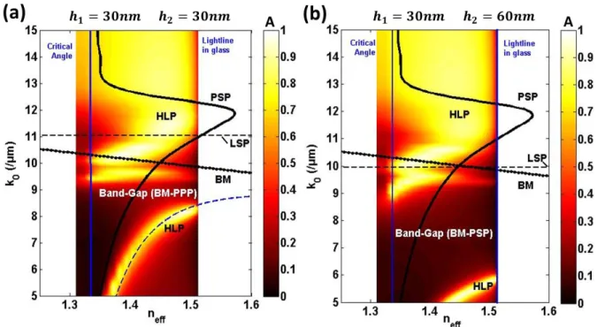
Excitation of the HLP mode in the array of nanocylinders on a metallic film. Finally, the
absorption (A) for the different modes present in the complete structure (Figure 1) is shown in
Figure 3, for an incident TM polarized light, and two different heights of the nanocylinder in the
Kretschmann configuration. For TE polarized light, no modes exist in the system (data not
shown).
Figure 2. (a) Normalized absorption (A) as a function of k0 and neff = kx/k0 in a uniform gold
film placed on a BK7 substrate with a height of h1 = 60 nm. The PSP dispersion as calculated by Eq.1 is also shown (black dashed-dotted). (b-c) Absorption maps for an array of cylinders of 50 nm in diameter with a period of 200 nm placed on a BK7 substrate for two values of the cylinder height (b) h2 = 30 nm, and (c) h2 = 60 nm. For comparison, the absorption curve for a single cylinder as a function of k0 is also shown (blue line) as well as the fulfillment of
The presence of the mode marked as BM (Bragg Mode) can be explained as follows: the PSP
in the thin film is partially reflected by the edges of the nanostructure array. Thus, we have two
contra-propagating PSP modes with the same in plane wave vector. The Bragg condition 52 for
the constructive interference of such contra-propagating modes can be written as
𝑘𝐵𝑀 = 𝑘𝑝𝑠𝑝± 𝑚𝑘𝐵 (2)
where m is an integer. kB is the Bragg wave vector given by 2π/Λ for the structure with period
Λ. When the Bragg condition is fulfilled, a localized plasmonic mode is obtained with a field
confined around the cylinders. We see in Figure 3 that the dispersion of the BM resonance
follows closely the fulfillment of the Bragg condition calculated in Equation 2 with m = 1. A
little shift from Equation 2 may be expected as the true values of kpsp are not exactly as that
Figure 3. Normalized absorption (A) of the structure as a function of k0 and neff = kx/k0 for h1
= 30 nm and h2 = 30 nm (a), and 60 nm (b). The dispersion curves for the PSP and BM as calculated by Eq.1 and Eq.2, respectively, are shown. The resonance frequency of the LSP was calculated using the FEM method for a single cylinder. The dispersion for the HLP mode calculated using Eq.3 is also shown for h2 = 30 nm (blue dashed).
predicted in Equation 1 for lower heights of the gold film. The shift can also be the result of the
coupling between the BM and the individual localized plasmonic mode. The excitation of this
mode follows the same principle as that of the SLR mode mentioned earlier. The difference lies
in the fact that in the case of the BM, the energy comes from the propagation plasmons (PSP),
while for the SLR it originates from the diffraction orders from the structure. We will henceforth
use the nomenclature ‘SLR’ for the mode excited in the nanostructure array on glass substrate
and ‘BM’ for that with the nanostructure array on the gold film.
Another striking feature of the absorption map is the two modes marked in Figure 3 as HLP,
which have a similar dispersion as the PSP modes shown in Figure 2(a). These modes are excited
by the PSP present in the thin gold film and this is further verified by the fact that these modes
do not exist for TE polarized incidence. To get a better understanding of this HLP mode, we can
consider the structure as a combination of two harmonic oscillators namely the PSP, and the BM.
It is well known 53 that such a coupling of harmonic oscillators results in the characteristic
anti-crossing phenomenon and a frequency splitting. 54 55 In Figure 3, we observe such a frequency
splitting with the two modes on both sides of the resonance frequencies of the BM mode. The
characteristic frequencies of two coupled harmonic oscillators can be written as:
𝜔𝐻𝐿𝑃∓ =1
2(𝜔𝑝𝑠𝑝2 + 𝜔𝐵𝑀2 + 2𝐾 ∓ √(𝜔𝑝𝑠𝑝2 − 𝜔𝐵𝑀2 ) 2
+ 4𝐾2) (3)
where K is the coupling coefficient, ωpsp, and ωBM are the resonance frequencies of the PSP
and BM, respectively. The dispersion of the lower branch of the HLP mode using Equation 3 is
shown in Figure 3. We see it closely follows the results obtained from the rigorous calculations
which validate our interpretation of the origin of the HLP mode.
namely the PSP, BM, and LSPR. In such a situation, the photonic bandgap can be expected to
increase and the frequencies of the HLP mode moves further away from the frequencies of both
the PSP, and BM. We see such a broadening of the bandgap in Figure 3 for h2 = 60 nm. Such a
coupling could be analytically expressed using a 3×3 coupling matrix, but with some unknown
coupling parameters.
Effect of different heights on the HLP mode position. The effects of h1 (gold film height) and h2 (cylinder height) were studied. Firstly, the resonance frequencies of the modes are not
expected to change with h1 as it only affects the PSP mode and its dispersion is largely
independent of the film height. Indeed, this is observed on Figure 4(a). On the contrary, the
position of the HLP mode strongly varies with the cylinder height (Figure 4(b)). This is
explained by the coupling between the BM and PSP modes, which is stronger when the cylinder
height is increased, thus pushing the HLP mode to higher wavelengths (lower k0). Also the LSP
mode shifts to higher wavelengths with increasing height as can be seen in Figure 2(b-c) and this
further causes a red-shift of the HLP. We see a somewhat linear dependence of the resonance
wavelength of the HLP mode and the cylinder height (Figure 4(c)). This gives the opportunity to
tune the resonance wavelength of the HLP mode, over a range of 1000nm, depending on the
application, by changing the cylinder height (h2) while retaining the same high field intensity
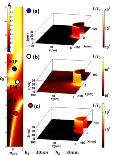
Electric field intensity distribution of modes. The electric field intensity distributions (I =
Ex2+Ey2+Ez2) normalized to the incident field intensity (I0), at each point over one period of the
structure for the 3 modes (HLP and BM) are shown in Figure 5. For all modes, the field Figure 4. (a) Normalized absorption curve of the HLP mode as a function of k0 for three
different heights of the gold film (h1) with fixed cylinder height (h2 = 30 nm). The curves are shown at neff = 1.42 (b) same for three different cylinder heights with a gold film height
fixed at h1 = 30 nm. The vertical solid lines represents the calculated BM position using Eq.2 at neff=1.42.(c) Resonance Wavelength of HLP mode for h1=30nm with different cylinder heights (h2).
For the lower frequency branch of the HLP mode, we see a strong confinement of the field
around the cylinder top with a symmetric distribution. This is similar to the field distributions we
expect in dipoles or for LSP mode. We therefore have a field distribution similar to LSP modes
and a dispersion similar to PSP modes, which further validates the fact that this mode is a result
of coupling between the two. For BM mode, we have an asymmetric intensity distribution with
more field intensity concentrated on the cylinder edge facing the direction of incidence. A closer
look at the metal film surface (z = 0) shows a weak sinusoidal variation of the intensity along the Figure 5. Normalized intensity distribution (I/I0), in logarithmic scale, of the different modes over one half-period (200 nm) of the array for h1 = 30 nm and h2 = 30 nm. The nanocylinder is located at x = 0, y = 0, and z = 0. The intensity was calculated for different values of k0,
and neff, where the absorption of each mode is maximum. (a) k0 = 10.33 µm-1, neff = 1.42; (b)
k0 = 9.60 µm-1, neff =1.46; (c) k0 = 7.20 µm-1, neff = 1.42. The positions on the (k0,neff)
axes of the PSP propagation (x-axis), which is expected from the standing wave formed by the
interference of the contra propagating PSPs. Finally, for the higher frequency branch of the HLP
mode, we have a somewhat orthogonal distribution to that of its lower frequency branch with the
field intensity being concentrated around the bottom edge of the cylinders.
We then compare the intensity distribution of the HLP mode (lower frequency branch) to that
of the classical resonance mode (SLR) in a cylinder array without gold film. Figure 6 shows, in
the plane of incidence (x-z plane), the intensity variation at a distance of 1 nm from the surface
with respect to curvilinear coordinates. The fact that the field intensity distribution is not exactly
symmetric with respect to the nanostructure geometry is due the direction of the propagating
plasmons. Both the SLR and the HLP modes have much higher field intensity than the BM,
which is also the mode we expect, when the structure is excited from the nanostructure side (see
supplementary data). This validates the benefit of illuminating the structures in the Kretschmann
configuration as compared to excitation from the nanostructure side. It is clear that the HLP
mode obtained with a gold film below the cylinder array gives the highest field intensity on the
nanostructure top surface. Both SLR and HLP modes show some very high intensity peaks
predicted by the numerical model at the top and bottom corners of the structure which will
probably not be observed as such, first because their exact amplitude depends on the mesh
finesse used in the numerical simulation and also because in a real sample, the edges will not be
perfect. However, we have carefully checked that the value of the integral of intensity as
calculated in the next section, which is the important quantity for biomolecular detection, is
largely independent of the mesh finesse.
Mean intensity enhancement. As we are mainly interested in the overall sensitivity gain due to
the nanostructure, we have calculated the surface integral of the intensity distribution at a
distance of 1 nm from the surface of the cylinders (Scyl) as
𝐼𝑆 = 1
𝑆𝑐𝑦𝑙∬ 𝐼(𝑆) 𝑑𝑆𝑆𝑐𝑦𝑙 (4)
The dependence of the integrated intensity on the effective refractive index (neff) for the HLP and
SLR mode is shown in Figure 7. As before, it was calculated for a value of h1 = 30 nm and
shown for two values of h2 (30 nm and 60 nm). We can see that the mean intensity around the
cylinders is enhanced up to 3 times when using the HLP mode compared to the classical SLR
mode in a nanostructure array. Such an enhancement can prove to be very useful in SPR
applications, where the sensitivity strongly depends on the field intensity56, and even more for Figure 6. Intensity profile (I/I0) in logarithmic scale with respect to the curvilinear coordinates (x) at the metal-water interface in the incidence plane for excitation in the Kretschmann configuration. For h2 = 30 nm (a), and 60 nm (b) without the gold film, and with the gold film of 30 nm height below the cylinders. The curves are shown at neff = 1.42,
and the cylinders are centered at 0 on the curvilinear coordinates and excitation in the Kretschmann configuration.
SERS 57 where the signal is proportional to the surface integral of I2. It can be shown that we
have an enhancement up to 9 times for [∬I2(S) dS]/Scyl obtained with the HLP mode as compared to the SLR mode (see Supplementary data). Thus such a structure can be effectively
used as a substrate for both the processes. 587 The HLP mode also has a mean intensity higher by
an order of magnitude (and surface integral of I2 up to 102 times) as compared to that of the BM
(see Supplementary data). Applications that require high field intensity can therefore take
advantage of the HLP mode in the Kretschmann configuration as compared to using the BM.
For biosensing applications, the biomolecules may be difficult to localize selectively only Figure 7. (a) Integrated intensity IS with h2 = 30 nm, with and without a 30 nm gold film, as a function of neff. (b) Same for h2 = 60 nm. The excitation is in the Kretschmann
the array may be more useful to estimate the performance of the structures. We have observed
that the field enhancement of the HLP mode with respect to the SLR mode over the entire
surface of one structure period is a bit higher than that shown in Figure 7 (see Supplementary
data). Because the HLP mode results from the coupling of propagation plasmons and has a
higher field distribution far from the cylinders than the SLR mode (Figure 6), we can expect a
higher field intensity enhancement for the HLP mode than the SLR mode when the entire surface
of an unit period of the structure is taken into account.
Experimental results. The nanostructure shown in Figure 1, with h1 = 30 nm and h2 = 30 nm, was fabricated by Electron Beam Lithography in order to have a good control of the size, shape
and distance between nanocylinders. A thin layer of 3 nm titanium was used for adhesion of the
gold film on the BK7 substrate. SEM images (Figure 8(a)) shows that the resulting gold
nanocylinders have a mean diameter of around 50 nm and a periodicity of 200 nm. The structure
was characterized by a SPR imaging system based on spectral scanning modality similar to a
previously reported setup (see Supplementary data).6 59 Here, the normalized reflectivity (R)
(TM reflectivity divided by TE reflectivity) of the sample is measured as a function of the
incident wave vector k0 and effective index neff. For the numerical simulation, the Titanium
adhesion layer below the gold film was also taken into consideration. As can be seen in Figure
8(b), a good agreement between the experimental results and the exact numerical simulation is
obtained for the HLP mode and thus this mode can be effectively excited using the Kretschmann
setup. The BM is somehow weaker in the experiment than what is predicted by the simulation.
As can be seen from Figure 4(a), the absorption of the BM strongly depends on the gold film
CONCLUSION
In summary, we have numerically calculated the absorption as a function of excitation
wavelength, and incident internal angle for an array of metallic nanocylinders with and without
an underlying thin metallic film in the Kretschmann configuration. We have shown that mean
field intensity around the array of nanostructures can be enhanced by placing the thin metallic
film below the array as compared to the SLR mode excited in the array on a glass substrate in the
Kretschmann configuration. By taking advantage of interference of the contra-propagating Figure 8. (a) SEM image of gold cylinders with a diameter of 50 nm, a period of 200 nm, and a height of 30 nm on a 30 nm gold film. (b) Reflectivity (R) of the structure as a function of k0, and neff = kx/k0 calculated by numerical simulation, and measured
experimentally. The position of the BM mode, as calculated by Equation 2, is also shown (dotted).
the structure, we can excite the Bragg Mode in the array of metallic nanostructures. This mode is
similar to the plasmonic modes that can be excited with incidence from the nanostructure side.
However, in the Kretschmann configuration the harmonic coupling between the propagating
surface plasmon mode of the thin film and the Bragg modes results in a new hybrid mode. This
Hybrid Lattice Plasmon (HLP) mode has a strong dispersion, and thus can be tuned effectively
over a wide range of excitation wavelengths. The tunability can also be achieved by changing the
height of the cylinder (over a range of 1000nm in resonance wavelength of the HLP).
Indeed, we have fabricated the nanostructures by electron beam lithography and experimentally
confirmed that the HLP mode can be excited using the conventional Kretschmann configuration.
The near-field intensity excited in such configurations as well as the mean field intensity
distribution was also calculated and proved that excitation of the HLP mode also leads to a
significant increase in the mean field intensity around the nanostructures. We can conclude that
this type of structure can be used effectively for applications that need such a high confinement
of the field intensity, such as SERS and SPR detection.
Methods
Numerical Simulations.
For the uniform metallic film we have used the well-known Rouard method, and its
generalization to absorbing metallic thin films (see Figure 2).60 The refractive indices of gold
used for simulations are the values of Johnson and Christy.61 For the nanostructures, firstly single
cylinders placed at the BK7-Water interface were characterized using the Finite Element Method
(FEM) with a perfectly matched layer (PML) surrounding the cylinders.62 Then, an array of such
FEM, and the periodic Fourier Modal Method (FMM).63 This hybrid method gives accurate
rigorous results with limited consumption of time and memory.646566
The electric and magnetic fields for the structure were calculated for different values of
wavelength (λ), and different plane incidence wave-vectors using the Hybrid method.(kx =
k0nbsinθ, where k0 = 2π/λ, nb the refractive index of the incident medium, and θ is the incidence
angle, as shown in Figure 1). From the calculated fields we derived the value of the absorption of
the nanostructures with respect to the incidence EM field.
The idea is to calculate the fields for the periodic array using the FEM method, and then derive
the far field effects (reflectivity, transmission, and absorption) using the FMM (see Figure 3).
Finally, a gold film was placed between the cylinder array, and the BK7 layer. Electric field
distribution and the consequent far field response were studied using the same hybridized
method as mentioned above.
Nanostructure fabrication. BK7 substrates were cleaned in a piranha solution (3:1 ratio of
H2SO4 (98%) and H2O2 (30%)) for 10 minutes. After a wash step by deionized water, a layer of 3
nm titanium followed by a layer of 30 nm gold, were deposited by E-beam evaporation. Then, a
layer of around 75 nm of poly(mehtylmethacrylate) (PMMA) was deposited by spin-coating on
glass substrates, and then baked for 15 minutes at 150°C. Patterns were then obtained by EBL
followed by a development step of the exposed regions in a mixture of methylisobutylketone
(MIBK), and isopropanol (ISO) (MIBK/ISO ratio: 1:3) for around 90 seconds. After a gold
evaporation step, nanocylinders were obtained via a lift-off process carried out by dipping the
substrate in acetone for several hours. The obtained structures have a period of around 200 nm,
Acknowledgements. The authors acknowledge IDEX Paris Saclay, and ANR P2N
(ANR-12-NANO-0016) as well as CNANO IDF, Labex NanoSaclay, and LUMAT for partial funding of
the project. IOGS/CNRS is also part of the European Network of Excellence in BioPhotonics:
Photonics for Life (P4L).
REFERENCES AND NOTES
1. Barnes, W. L.; Dereux, A.; Ebbesen, T. W., Surface plasmon subwavelength optics.
Nature 2003, 424 (6950), 824-830.
2. Schuller, J. A.; Barnard, E. S.; Cai, W. S.; Jun, Y. C.; White, J. S.; Brongersma, M. L., Plasmonics for extreme light concentration and manipulation (vol 9, pg 193, 2010). Nat Mater
2010, 9 (4).
3. Homola, J., Surface plasmon resonance sensors for detection of chemical and biological species. Chem Rev 2008, 108 (2), 462-493.
4. Bardin, F.; Bellemain, A.; Roger, G.; Canva, M., Surface plasmon resonance spectro-imaging sensor for biomolecular surface interaction characterization. Biosensors &
Bioelectronics 2009, 24 (7), 2100-2105.
5. Mannelli, I.; Courtois, V.; Lecaruyer, P.; Roger, G.; Millot, M. C.; Goossens, M.; Canva, M., Surface plasmon resonance imaging (SPRI) system and real-time monitoring of DNA biochip for human genetic mutation diagnosis of DNA amplified samples. Sensor Actuat
B-Chem 2006, 119 (2), 583-591.
6. Nakkach, M.; Duval, A.; Ea-Kim, B.; Moreau, J.; Canva, M., Angulo-spectral surface plasmon resonance imaging of nanofabricated grating surfaces. Opt Lett 2010, 35 (13), 2209-2211.
7. Meyer, S. A.; Auguie, B.; Le Ru, E. C.; Etchegoin, P. G., Combined SPR and SERS Microscopy in the Kretschmann Configuration. J Phys Chem A 2012, 116 (3), 1000-1007.
8. Ropers, C.; Neacsu, C. C.; Elsaesser, T.; Albrecht, M.; Raschke, M. B.; Lienau, C., Grating-coupling of surface plasmons onto metallic tips: A nanoconfined light source. Nano Lett
2007, 7 (9), 2784-2788.
9. Turker, B.; Guner, H.; Ayas, S.; Ekiz, O. O.; Acar, H.; Guler, M. O.; Dana, A., Grating coupler integrated photodiodes for plasmon resonance based sensing. Lab on a Chip 2011, 11 (2), 282-287.
10. Zia, R.; Selker, M. D.; Catrysse, P. B.; Brongersma, M. L., Geometries and materials for subwavelength surface plasmon modes. Journal of the Optical Society of America a-Optics
Image Science and Vision 2004, 21 (12), 2442-2446.
11. Myroshnychenko, V.; Rodriguez-Fernandez, J.; Pastoriza-Santos, I.; Funston, A. M.; Novo, C.; Mulvaney, P.; Liz-Marzan, L. M.; de Abajo, F. J. G., Modelling the optical response of gold nanoparticles. Chem Soc Rev 2008, 37 (9), 1792-1805.
12. Jain, P. K.; Eustis, S.; El-Sayed, M. A., Plasmon coupling in nanorod assemblies: Optical absorption, discrete dipole approximation simulation, and exciton-coupling model. J Phys Chem
13. Cunningham, A.; Muhlig, S.; Rockstuhl, C.; Burgi, T., Coupling of Plasmon Resonances in Tunable Layered Arrays of Gold Nanoparticles. J Phys Chem C 2011, 115 (18), 8955-8960. 14. Wang, Y. Q.; Yan, B.; Chen, L. X., SERS Tags: Novel Optical Nanoprobes for Bioanalysis. Chem Rev 2013, 113 (3), 1391-1428.
15. Ngo, H. T.; Wang, H. N.; Fales, A. M.; Vo-Dinh, T., Label-Free DNA Biosensor Based on SERS Molecular Sentinel on Nanowave Chip. Anal Chem 2013, 85 (13), 6378-6383.
16. Atwater, H. A.; Polman, A., Plasmonics for improved photovoltaic devices. Nat Mater
2010, 9 (3), 205-213.
17. Murphy, C. J.; Gole, A. M.; Stone, J. W.; Sisco, P. N.; Alkilany, A. M.; Goldsmith, E. C.; Baxter, S. C., Gold Nanoparticles in Biology: Beyond Toxicity to Cellular Imaging. Accounts
Chem Res 2008, 41 (12), 1721-1730.
18. Mayer, K. M.; Hafner, J. H., Localized Surface Plasmon Resonance Sensors. Chem Rev
2011, 111 (6), 3828-3857.
19. Le, F.; Brandl, D. W.; Urzhumov, Y. A.; Wang, H.; Kundu, J.; Halas, N. J.; Aizpurua, J.; Nordlander, P., Metallic nanoparticle arrays: A common substrate for both surface-enhanced Raman scattering and surface-enhanced infrared absorption. Acs Nano 2008, 2 (4), 707-718. 20. Eustis, S.; El-Sayed, M. A., Why gold nanoparticles are more precious than pretty gold: Noble metal surface plasmon resonance and its enhancement of the radiative and nonradiative properties of nanocrystals of different shapes. Chem Soc Rev 2006, 35 (3), 209-217.
21. Juan, M. L.; Righini, M.; Quidant, R., Plasmon nano-optical tweezers. Nat Photonics
2011, 5 (6), 349-356.
22. Wang, X. L.; Gogol, P.; Cambril, E.; Palpant, B., Near- and Far-Field Effects on the Plasmon Coupling in Gold Nanoparticle Arrays. J Phys Chem C 2012, 116 (46), 24741-24747. 23. Koenderink, A. F., Plasmon Nanoparticle Array Waveguides for Single Photon and Single Plasmon Sources. Nano Lett 2009, 9 (12), 4228-4233.
24. Li, J. T.; Cushing, S. K.; Zheng, P.; Meng, F. K.; Chu, D.; Wu, N. Q., Plasmon-induced photonic and energy-transfer enhancement of solar water splitting by a hematite nanorod array.
Nat Commun 2013, 4.
25. Khoury, C. G.; Norton, S. J.; Vo-Dinh, T., Plasmonics of 3-D Nanoshell Dimers Using Multipole Expansion and Finite Element Method. Acs Nano 2009, 3 (9), 2776-2788.
26. Live, L. S.; Dhawan, A.; Gibson, K. F.; Poirier-Richard, H. P.; Graham, D.; Canva, M.; Vo-Dinh, T.; Masson, J. F., Angle-dependent resonance of localized and propagating surface plasmons in microhole arrays for enhanced biosensing. Analytical and Bioanalytical Chemistry
2012, 404 (10), 2859-2868.
27. Yu, Q. M.; Guan, P.; Qin, D.; Golden, G.; Wallace, P. M., Inverted size-dependence of surface-enhanced Raman scattering on gold nanohole and nanodisk arrays. Nano Lett 2008, 8 (7), 1923-1928.
28. Zhou, F.; Liu, Y.; Cai, W. P., Huge local electric field enhancement in hybrid plasmonic arrays. Opt Lett 2014, 39 (5), 1302-1305.
29. Lodewijks, K.; Ryken, J.; Van Roy, W.; Borghs, G.; Lagae, L.; Van Dorpe, P., Tuning the Fano Resonance Between Localized and Propagating Surface Plasmon Resonances for Refractive Index Sensing Applications. Plasmonics 2013, 8 (3), 1379-1385.
30. Zou, S. L.; Schatz, G. C., Silver nanoparticle array structures that produce giant enhancements in electromagnetic fields. Chem Phys Lett 2005, 403 (1-3), 62-67.
32. Väkeväinen, A. I.; Moerland, R. J.; Rekola, H. T.; Eskelinen, A. P.; Martikainen, J. P.; Kim, D. H.; Törmä, P., Plasmonic Surface Lattice Resonances at the Strong Coupling Regime.
Nano Lett 2013.
33. Lovera, A.; Gallinet, B.; Nordlander, P.; Martin, O. J. F., Mechanisms of Fano Resonances in Coupled Plasmonic Systems. Acs Nano 2013, 7 (5), 4527-4536.
34. Gallinet, B.; Martin, O. J. F., Refractive Index Sensing with Subradiant Modes: A Framework To Reduce Losses in Plasmonic Nanostructures. Acs Nano 2013, 7 (8), 6978-6987. 35. Aubry, A.; Lei, D. Y.; Maier, S. A.; Pendry, J. B., Plasmonic Hybridization between Nanowires and a Metallic Surface: A Transformation Optics Approach. Acs Nano 2011, 5 (4), 3293-3308.
36. Papanikolaou, N., Optical properties of metallic nanoparticle arrays on a thin metallic film. Physical Review B 2007, 75 (23).
37. Lassiter, J. B.; McGuire, F.; Mock, J. J.; Ciraci, C.; Hill, R. T.; Wiley, B. J.; Chilkoti, A.; Smith, D. R., Plasmonic Waveguide Modes of Film-Coupled Metallic Nanocubes. Nano Lett
2013, 13 (12), 5866-5872.
38. Zuloaga, J.; Prodan, E.; Nordlander, P., Quantum Description of the Plasmon Resonances of a Nanoparticle Dimer. Nano Lett 2009, 9 (2), 887-891.
39. Davis, T. J.; Gomez, D. E.; Vernon, K. C., Simple Model for the Hybridization of Surface Plasmon Resonances in Metallic Nanoparticles. Nano Lett 2010, 10 (7), 2618-2625. 40. Forestiere, C.; Dal Negro, L.; Miano, G., Theory of coupled plasmon modes and Fano-like resonances in subwavelength metal structures. Physical Review B 2013, 88 (15).
41. Miroshnichenko, A. E.; Flach, S.; Kivshar, Y. S., Fano resonances in nanoscale structures. Rev Mod Phys 2010, 82 (3), 2257-2298.
42. Luk'yanchuk, B.; Zheludev, N. I.; Maier, S. A.; Halas, N. J.; Nordlander, P.; Giessen, H.; Chong, C. T., The Fano resonance in plasmonic nanostructures and metamaterials. Nat Mater
2010, 9 (9), 707-715.
43. Francescato, Y.; Giannini, V.; Maier, S. A., Plasmonic Systems Unveiled by Fano Resonances. Acs Nano 2012, 6 (2), 1830-1838.
44. Gantzounis, G.; Stefanou, N.; Papanikolaou, N., Optical properties of periodic structures of metallic nanodisks. Physical Review B 2008, 77 (3).
45. Butt, H.; Dai, Q.; Rajesekharan, R.; Wilkinson, T. D.; Amaratunga, G. A. J., Plasmonic Band Gaps and Waveguide Effects in Carbon Nanotube Arrays Based Metamaterials. Acs Nano
2011, 5 (11), 9138-9143.
46. Raether, H., Surface-Plasmons on Smooth and Rough Surfaces and on Gratings. Springer
Tr Mod Phys 1988, 111, 1-133.
47. Li, Y.; Zhao, K.; Sobhani, H.; Bao, K.; Nordlander, P., Geometric Dependence of the Line Width of Localized Surface Plasmon Resonances. J Phys Chem Lett 2013, 4 (8), 1352-1357.
48. Ni, W. H.; Ambjornsson, T.; Apell, S. P.; Chen, H. J.; Wang, J. F., Observing Plasmonic-Molecular Resonance Coupling on Single Gold Nanorods. Nano Lett 2010, 10 (1), 77-84.
49. Carron, K. T.; Fluhr, W.; Meier, M.; Wokaun, A.; Lehmann, H. W., Resonances of Two-Dimensional Particle Gratings in Surface-Enhanced Raman-Scattering. J Opt Soc Am B 1986, 3 (3), 430-440.
50. Rodriguez, S. R. K.; Abass, A.; Maes, B.; Janssen, O. T. A.; Vecchi, G.; Rivas, J. G., Coupling Bright and Dark Plasmonic Lattice Resonances. Phys Rev X 2011, 1 (2).
51. Kravets, V. G.; Schedin, F.; Grigorenko, A. N., Extremely narrow plasmon resonances based on diffraction coupling of localized plasmons in arrays of metallic nanoparticles. Phys Rev
Lett 2008, 101 (8).
52. Barnes, W. L.; Preist, T. W.; Kitson, S. C.; Sambles, J. R., Physical origin of photonic energy gaps in the propagation of surface plasmons on gratings. Physical Review B 1996, 54 (9), 6227-6244.
53. Novotny, L., Strong coupling, energy splitting, and level crossings: A classical perspective. Am J Phys 2010, 78 (11), 1199-1202.
54. Kelf, T. A.; Sugawara, Y.; Baumberg, J. J.; Abdelsalam, M.; Bartlett, P. N., Plasmonic band gaps and trapped plasmons on nanostructured metal surfaces. Phys Rev Lett 2005, 95 (11). 55. Okamoto, T.; Simonen, J.; Kawata, S., Plasmonic band gaps of structured metallic thin films evaluated for a surface plasmon laser using the coupled-wave approach. Physical Review B
2008, 77 (11).
56. Chamtouri, M.; Sarkar, M.; Moreau, J.; Besbes, M.; Ghalila, H.; Canva, M., Field enhancement and target localization impact on the biosensitivity of nanostructured plasmonic sensors. J. Opt. Soc. Am. B 2014, 31 (5), 1223-1231.
57. Moskovits, M., Surface-enhanced Raman spectroscopy: a brief perspective. Top Appl
Phys 2006, 103, 1-17.
58. Liu, Y.; Xu, S. P.; Tang, B.; Wang, Y.; Zhou, J.; Zheng, X. L.; Zhao, B.; Xu, W. Q., Note: Simultaneous measurement of surface plasmon resonance and surface-enhanced Raman scattering. Rev Sci Instrum 2010, 81 (3).
59. Sereda, A.; Moreau, J.; Canva, M.; Maillart, E., High performance multi-spectral interrogation for surface plasmon resonance imaging sensors. Biosensors and Bioelectronics
2014, 54 (0), 175-180.
60. Lecaruyer, P.; Maillart, E.; Canva, M.; Rolland, J., Generalization of the Rouard method to an absorbing thin-film stack and application to surface plasmon resonance. Applied Optics
2006, 45 (33), 8419-8423.
61. Johnson, P. B.; Christy, R. W., Optical Constants of the Noble Metals. Physical Review B
1972, 6 (12), 4370-4379.
62. Dossou, K.; Byrne, M. A.; Botten, L. C., Finite element computation of grating scattering matrices and application to photonic crystal band calculations. Journal of Computational Physics
2006, 219 (1), 120-143.
63. Moharam, M. G.; Grann, E. B.; Pommet, D. A.; Gaylord, T. K., Formulation for Stable and Efficient Implementation of the Rigorous Coupled-Wave Analysis of Binary Gratings.
Journal of the Optical Society of America a-Optics Image Science and Vision 1995, 12 (5),
1068-1076.
64. Besbes, M.; Hugonin, J. P.; Lalanne, P.; van Haver, S.; Janssen, O. T. A.; Nugrowati, A. M.; Xu, M.; Pereira, S. F.; Urbach, H. P.; van de Nes, A. S.; Bienstman, P.; Granet, G.; Moreau, A.; Helfert, S.; Sukharev, M.; Seideman, T.; Baida, F. I.; Guizal, B.; Van Labeke, D., Numerical analysis of a slit-groove diffraction problem. Journal of the European Optical Society-Rapid
Publications 2007, 2.
65. Hugonin, J. P.; Besbes, M.; Lalanne, P., Hybridization of electromagnetic numerical methods through the G-matrix algorithm. Opt Lett 2008, 33 (14), 1590-1592.
66. Sarkar, M.; Chamtouri, M.; Moreau, J.; Besbes, M.; Canva, M., Introducing 2D confined propagating plasmons for surface plasmon resonance sensing using arrays of metallic ribbons.