The Consequences of the Enterprise not Engaging the
Manufacturing System Design
by
Jey Y. Won
B.S. Mechanical Engineering
Rutgers University, School of Engineering, 2000
Submitted to the Department of Mechanical Engineering in Partial Fulfillment of the Requirements for the Degree of
Master of Science
at the
MASSACHUSETTS INSTITUTE OF TECHNOLOGY
June 2002
9 2002 Massachusetts Institute of Technology All rights reserved
BARKr-> MASSACHUSETTS INSTITUTE OF TECHNOLOGY
LIBRARIES
I
Signature of Author: Departgewf of Mechani jJ ng ng 202 Certified by: David S. Cochran Associate Professor of Mechanical Engineering .Thesis SupervisorAin A. Sonin Chairman, Committee on Graduate Students Accepted by:
The Consequences of the Enterprise not Engaging the
Manufacturing System Design
by
Jey Y. Won
Submitted to the Department of Mechanical Engineering on May 10, 2002 in Partial Fulfillment of the Requirements for the Degree of Master of Science
ABSTRACT
Currently much of the conventional focus on system design has been directed exclusively upon the system's physical structures and behaviors. Various approaches have been developed to describe, understand and prescribe, in great detail, how systems should be structurally designed and physically operated. However, in a number of cases, these approaches only result in transitory improvement and a reversion back to prior practices. The rational notion of 'changing the behaviors by working on the behaviors' results in disappointment, and systems that have achieved enduring success seem contradictory to logic and paradoxical in nature. However, these design methodologies often do not explicitly and coherently map the physical system design approach with a systems thinking. For systems that include both technical and human interactions, one must first recognize that the thinking creates the structure that results in the behavior of the system. The thesis presented herein provides an introduction into the development of an ideal systems engineering model based upon the thinking-structure-behavior model, and proposal of the unification of two powerful design approaches-axiomatic design and system dynamics. In order to rationalize the seemingly paradoxical trap of behavior-focus, the "Chasm of Paradox" model is developed. The "chasm" model relates the notion of paradoxes and paradigm shifts to the thinking-structure-behavior model.
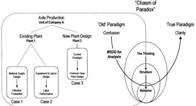
The "Chasm of Paradox" model is applied in an application-based case study in the automotive components business. The case studies strongly support the notion that the same thinking that resulted in prior poor system performance will reincarnate itself in another unstable system design that produces poor results-even in light of the
opportunity for 'green field' design. The hypothesis is that the enterprise must change its thinking before local changes to the manufacturing system design (i.e. the structure) and its performance (i.e. the behavior) can be successful. Only when the enterprise recognizes that 'they are part of the system, and they are the system' will paradigms shift and the apparent chasm be crossable. The thesis submits that the unified approach of axiomatic design and system dynamics is the bridge that enables a successful crossing.
Acknowledgements
Not only does this thesis mark the conclusion of a considerable academic endeavor (nearly twenty-one years of formal education), but it also represents a personal success that could not have been realized without the support of many individuals along the way. The thanks and gratitude I offer to these individuals is authentic and well-deserved.
First and foremost, I would like to thank my academic advisor, Professor David Cochran, for providing me the opportunity to join the Production System Design (PSD) laboratory. The in-depth exposure to both engineering and management disciplines in manufacturing systems will serve me well in both my future practical and academic endeavors.
Professor Cochran provided invaluable guidance throughout my tenure at MIT. But most importantly, he provided the space to develop my own thoughts and integrate my own personal creativity into the laboratory's research work. I would also like to thank my undergraduate advisor from Rutgers, Professor Constantinos Mavroidis, for also giving me an opportunity to experiment, develop, and publish my ideas in an academic context. His support was key in providing me with a solid research foundation to build upon at MIT. To both my advisors, I am thankful for latitude and guidance.
My colleagues in the PSD lab have been key in making my stay in Room 35-135A both
productive and enjoyable. Thanks to Steve Hendricks, Yong-Suk Kim, Kola Masha, Zhenwei Zhao, and Quinton Ng for being lab-mates with me for the past two years. To
each of you I wish good things in life and congratulations on graduating with me this year. Thanks also goes to the rest of the 'multi-nationals' from the PSD lab-Henning
Rudolf, Martin Meyer, Patrick Neise, Soeren Guenther, Andreas Szentivanyi, Carlos Tapia, Memo Oropeza, Cesar Bocanegra, Jose Casteneda-Vega, Jong-Yoon Kim, Keith Low, Abhinav Shukla, Ania Mierzejewska, and Pat Smethers. A special thanks and recognition goes to Jochen Linck-a role model and friend.
Throughout my tenure at MIT, I've also had the opportunity to learn from some of the best professors in their respective fields. Of the many I have come across, these teachers in particular have helped shaped my thinking, developed my knowledge-base, and rejuvenated my desire to learn new concepts and intelligently challenge the 'hard problems'-Dr. Dan Whitney, Prof. Richard DeNeufville, and Dr. Jack Gill. I would also like to extend a special thanks to other educators outside of MIT. Working with Professor H. Thomas Johnson has been a great opportunity. His support and council has been invaluable. He has also been a model of continuous learning that still challenges people to think beyond their 'Newtonian paradigms' on systems. I would also like to express gratitude to Charlie Colosky and Ron Clemons for showing me pragmatic applications of system design. In particular Ron has reinforced the notion that respect is earned by hard work, and perseverance to 'do the right thing.'
Throughout my time at MIT, I have also established a number of relationships that have been invaluable to me because of their impact upon me both academically and personally.
A thanks to those LFM'ers who I've had the pleasure of learning with over the course of
my time at MIT Sloan-Tony Palumbo, Eric Schmidlin, D. David Johnson, Aaron Fyke, and Micah Samuels. A special thanks to Aubrey Williams-for those countless hours we spent in the machine shop building the 'bike rack.'
I'd also like to extend my sincerest thanks and gratitude to my friends at MIT and beyond
who've been with me through the ups and downs of life. Without my friends, life would not be as enjoyable or manageable. Thanks to those at MIT-Melissa, Laurel, Leigh, Stan, Sonny, Mike, the softball crew, and everyone else. Thanks for my friends from 'home', Rutgers, GSS, Morris Hills, and Sacred Heart School-Melissa, Brie, Jim, Mark, Brian C., Brian P., Paul, Avi, Kristin, Helen, Perrin, Tammy, Judy, Laurie, Mike, Mel, Rich, Ernie, May, Marian, Debjeet, Raf-Daddy, Jackal, Weasal, Leech, Agnes, and Yvonne. I'd like to also extend a hearty thanks to James Celestino-who has been both my house-mate and friend since the first days at Rutgers U.
There are so many who have supported or inspired me in many ways throughout my life. So many so I cannot name them all here. However, among all the individuals who have had a tremendous influence upon my life, my family is the most important. My
siblings-Yhoumey, Eryhn, and Roney-have always been tremendously supportive of my endeavors, and in many ways, they have helped pave the way for my successes. For that, they must also take credit for my successes. Lastly, and most importantly, I want to sincerely thank both my parents-Jong-Suk (John) and Kyong-Nyun (Linda)-for the person that I am today. They have both been the archetypal ideal of the successes financially poor immigrants can achieve through hard work, dedication, perseverance, and a rich love for family. For my family's enduring support, I am forever thankful.
Table of Contents
ACKNOW LEDGEMENTS... 5
TABLE OF CONTENTS... 7
LIST OF FIGURES... 9
LIST OF TABLES AND EQUATIONS ... 12
LIST OF ACRONYMS... 13
Chapter 1 Introduction... 14
1.1 Thesis Motivation ... 14
1.2 Thesis Overview ... 15
Chapter 2 Analysis of System Design Approaches... 17
2.1 Systems and Systems Engineering... 17
2 .1.1 Sy stem s ... . 1 7 2.1.2 Systems Engineering ... 17
2.2 System D esign ... 19
2.3 Classification of an Ideal Systems Engineering Approach... 20
2.4 Review of Five General Design Approaches... 24
2.4.1 Introduction... . 24
2.4.2 Axiomatic Design... 24
2.4.3 Quality Function Deployment (QFD) - House of Quality... 29
2.4.4 Problem-Solving Hierarchy Mapping - Issue Trees and MECE... 32
2.4.5 Design Structure Matrix (DSM)... 35
2.4.6 System Dynamics ... 38
2.5 Analysis of Five General Design Approaches ... 41
2.5.1 A General Model to Analyze the Underlying Thinking... 41
2.5.2 Axiomatic Design... 43
2.5.3 Quality Function Deployment (QFD) - House of Quality... 45
2.5.4 Problem Solving Hierarchy Mapping -Issue Trees and MECE... 47
2.5.5 Design Structure Matrix (DSM)... 48
2.5.6 System Dynamics ... 49
2.5.7 Comparative Thinking Amongst the General Design Approaches... 51
Chapter 3 Manufacturing System Design Decomposition ... 56
3.1 Introduction ... 56
3.2 M anufacturing System s ... 56
3.3 M anufacturing System D esign... 56
3.4 Manufacturing System Design Decomposition (MSDD)... 57
3.5 Production System Design and Deployment Framework... 62
3.6 The MSDD Questionnaire and Evaluation Tool... 63
Chapter 4 Axle Production Case Study ... 65
4.1 Introduction ... . 65
4.2 Case 1: Relationship of Material Supply Design to Effective Production... 66
4.2.1 The 9.75 Case/Carrier Assembly Line - Department 91... 67
4.2.2 The Rainbow Differential Case Assembly Cell - Dept. 15 ... 73
4.2.3 Relationship to The Thinking... 79
4.3 Case 2: Relationship of Equipment & Layout Design to Labor Performance. 80 4.3.1 High Speed Axle Assembly Line - Department 16... 80
4.3.2 Case/Carrier Loop Assembly Line - Department 91... 83
4.3.3 Case/Carrier Assembly Cell - Rainbow ... 85
5.2.5 Structure-Behavior Relationships... 86
4.3.4 Relationship to the Thinking ... 87
4.4 Case 3: Premium Gear Plant - Replicating the Old Paradigm ... 88
4.4.1 L ay o ut ... . . 88
4.4.2 E quip m ent D esign... 89
4.4.3 M aterial F low ... 90
4.4.4 Internal MSDD Evaluation - A Perspective on Plant 2's Thinking... 91
4.4.5 Comparison and Analysis of Evaluations - Differences in Thinking ... 93
4.4.6 Consequences of the Thinking ... 94
4.5 C hapter Sum m ary ... 94
Chapter 5 Conclusions... 96
5.1 Insights from the Thesis... 96
List of Figures
Figure 1-1. General system engineering model [Cochran, Won, 2002]... 15
Figure 2-1. Typical relationship between systems engineering and system design ... 18
Figure 2-2. Synthesis, Evaluation, and Analysis [Adapted from Blanchard, Fabrycky, 19 9 8 ] ... 19
Figure 2-3. The Thinking drives Structure and Structure drives Behavior... 20
Figure 2-4. The thinking behind the ideal systems engineering approach ... 21
Figure 2-5. The ideal systems engineering model ... 23
Figure 2-6. The Patterns of Relationship in an Ideal System [Cochran, Won, 2002] ... 23
Figure 2-7. System design connects three domains ... 25
Figure 2-8. Representation of the mapping process [Suh, 2000]... 26
Figure 2-9. Mapping the FRs to the DPs ... 27
Figure 2-10. Simplified Axiomatic Design decomposition Process [Linck, 2001]... 29
Figure 2-11. House of Quality's five key elements... 30
Figure 2-12. House of Quality [Hauser, Clausing, 1988]... 31
Figure 2-13. Issue-based problem solving [Accenture, 2002]... 32
Figure 2-14. Two types of issue-based problem solving approaches [Accenture, 2002] 33 Figure 2-15. Illustration of a data-driven tree for analysis [Accenture, 2002]... 34
Figure 2-16. Illustration of solution-driven BOM [adapted from Ulrich, Eppinger, 2000] ... 3 4 Figure 2-17. Diagraphs of three basic types of task dependencies [Ulrich, Eppinger, 2 0 0 0 ]. ... 3 5 Figure 2-18. Example of a design structure matrix [Ulrich, Eppinger, 2000]... 36
Figure 2-19. Causal loop diagram [Sterman, 2001]... 39
Figure 2-20. The resultant patterns of behavior--predicted and actual [Sterman, 2001]. 39 Figure 2-21. System dynamics of "Fixes that Fail" ... 40
Figure 2-22. General relationships in systems engineering ... 42
Figure 2-23. Development cycle for Axiomatic Design vs. Build-Test-Fix [Adapted from S u h , 2 0 0 2 ] ... 4 4 Figure 2-24. The Thinking behind Axiomatic Design... 45
Figure 2-25. The Thinking behind the House of Quality... 46
Figure 2-27. The Thinking behind the Design Structure Matrix ... 49
Figure 2-28. The Thinking behind System Dynamics ... 50
Figure 2-29. Comparison of the structural formation ... 51
Figure 2-30. Comparison of the thought formation... 52
Figure 2-31. Complete comparison of approaches ... 53
Figure 2-32. Our own mental models create the perception of paradox... 54
Figure 2-33. Clarity results from the right way of thinking... 54
Figure 2-34. Crossing the Chasm of Paradox ... 55
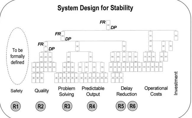
Figure 3-1. First 2 of 6 levels of the MSDD's mapping... 58
Figure 3-2. The MSDD and its different branches ... 58
Figure 3-3. Two-sided approach to design and implementation of stable systems ... 60
Figure 3-4. Control systems view of System Stability ... 60
Figure 3-5. The MSDD and the Six Requirements of System Stability ... 61
Figure 3-6. Illustration of score calculation... 63
Figure 3-7. Translation of average into a measure of "goodness"... 64
Figure 3-8. Illustration of a completed MSDD evaluation ... 64
Figure 4-1. Application of the 'Chasm of Paradox' model in axle production... 65
Figure 4-2. FRs that affect Material Supply Design and Operation ... 66
Figure 4-3. Illustration of external material location in Department 91 ... 67
Figure 4-4. Overall assessment of Dept 91 in 6 material supply FRs... 68
Figure 4-5. Schematic of Station 11-Flange Press... 69
Figure 4-6. Detailed view of workstation ... 69
Figure 4-7. Material supply in front of flange press station ... 70
Figure 4-8. Gravity feed rack feeding material to the workstation... 71
Figure 4-9. Illustration of material feed technique ... 71
Figure 4-10. Round-trip distances between Dept 91 and supplying departments ... 72
Figure 4-11. Comparative MSDD evaluations for Dept 91 (top) and Rainbow (bottom)74 Figure 4-12. Layout of Rainbow final assembly cell... 75
Figure 4-13. Schematic of Station #30-Flange Press... 76
Figure 4-14. M aterial supply to Station 30 ... 76
Figure 4-15. Schematic of Station #I 50-Diff Case Build-up ... 77
Figure 4-16. Material supply to diff case build-up station... 78
Figure 4-18. Work content breakdown of axle assembly line. ... 82
Figure 4-19. Trade-offs and Ideal Cycle Time for Capacity Selection in Cells [Cochran, 2 0 0 1] ... 8 2 Figure 4-20. Overall assessment of Dept 91 in Labor Branch... 83
Figure 4-21. Work content breakdown of case/carrier assembly line. ... 84
Figure 4-22. Overall assessment of Rainbow Assembly in Labor Branch... 85
Figure 4-23. Work content breakdown of Rainbow Assembly line. ... 86
Figure 4-24. Layout of Plant 2... 88
Figure 4-25. Possible material flow paths through plant ... 89
Figure 4-26. Plant l's blanking department layout (left) and Plant 2'sface hob layout (rig h t) ... 9 0 Figure 4-27. V alue stream m ap of Plant 2 ... 91
Figure 4-28. Internal MSDD evaluation result of Plant 2... 92
Figure 4-29. Answers from four respondents to FR-DP T51 ... 94
Figure 4-30. Trap of the Paradox... 95
List of Tables and Equations
Table 4-1. Performance of Station 11 in relation to Overall MSDD Evaluation Scores. 73
Table 4-2. Comparison of Dept 91 and Rainbow ... 74
Table 4-3. Performance of Stations 30 and 150 to Overall MSDD Evaluation Scores... 79
Table 4-4. Relationship of material supply upon production ... 80
Table 4-5. Performance of the three value streams in the Direct Labor Branch ... 87
Table 4-6. Top and bottom pair performers of Plant 2 ... 92
Table 4-7. Comparison of external and internal MSDD evaluation scores ... 93
Equation 2-1. U ncoupled design... 27
Equation 2-2. Path dependent design... 28
Equation 2-3. Coupled design... 28
Equation 2-4. Incom plete design ... 28
List of Acronyms
BOM Bill Of Materials
C Constraints
CA Customer Attributes
CLD Causal Loop Diagram
CT Cycle Time
DM Design Matrix
DP Design Parameter
DSM Design Structure Matrix
e.g. Exempli Gratia (for example)
FR Functional Requirement
i.e. Id Est (that is)
MECE Mutually Exclusive and Collectively Exhuastive
MRP Material Requirements Planning
MSDD Manufacturing System Design Decomposition
PSDD Production System Design and Deployment
R Requirement
ROI Return On Investment
S Solution
SWIP Standard Work In Process
TPS Toyota Production System
TSSC Toyota Supplier Support Center
VSM Value Stream Mapping
Chapter 1
Introduction
1.1
Thesis Motivation
Design approaches can be categorized into two broad, yet distinct, categories--design by philosophy and systems engineering [Duda, 2000]. Philosophy-based design is founded on a general high-level thinking that is understood and communicated-explicitly or implicitly-with the goal of achieving a holistic impact on all phases of design. A classic illustration is that of a rules-based approach to design. Rules-based approaches are
intended to communicate the essence of one's thinking in a manner that helps simplifies the direction of design. In contrast, a systems engineering approach is characterized as a more rigorous treatment of the design process. Systems engineering focuses on
designing systems in light of lifecycles of design, interdisciplinary complexity, defining requirements, and the hierarchical nature of designs [Blanchard, Fabrycky, 1998].
While a powerful as an approach to design, philosophy-based design requires a deep understanding of the underlying requirements and means to achieve them. By nature, philosophy-based design approaches do not necessarily reflect the concept of designing systems based on system requirements [Shukla, 2001]. The implicit nature of the thinking behind the philosophy-based design approaches, such as rules-of-thumb or maxims, calls for a lengthy, inductive learning process [Won, Cochran, Johnson, 2001]. Recall the difficulties in understanding someone's implicit thinking when questions are answered with "it depends" or the mysterious requests of Mr. Miyagi (Pat Morita in Karate Kid) to "wax the floor" and "paint the fence." The implication is that philosophy-based design is the result of the thinking behind system design. Once one understands the thinking, only then does the true usefulness of the philosophy, rules, and maxims become more clearly understood. This is the power-and bane--of philosophy-based approaches.
However, one can argue that engineering systems are complex and require a rigorous systems approach to harness and focus the knowledge of multiple constituents. In fact, Wu [1992] concurs that manufacturing system design must apply systems engineering methods to manage the complexity. Suh [1990] submits that one of the goals of
academic disciplines such as design, that universities have a role in condensing the "time required to learn a subject through the transmission of codified and generalized
knowledge." When a subject relies upon implicit thought processes that cannot be stated explicitly for others to understand, the subject can be learned only through experience, apprenticeship, or trial-and-error. Acceptance of trial-and-error as a design approach has been instilled in many as the norm. Recall the well-known adage claims 'we learn from our mistakes.' However, as the Quality VP of Toyota Motor Manufacturing - Kentucky put it, "the only thing we learn from out mistakes is not to do it that way" [Kreafle, 2001].
The precept of this thesis is that an ideal systems engineering approach should provide a framework that is consistent at the overall process level-first and foremost, a
consistency in its thinking. By focusing attention on the thinking process, deviations are permissible as long as the result is consistent with the intent. The result is a framework that is robust across a variety of systems [Cochran, Won, 2002]. As reflected in this
thesis, an ideal design approach requires aspects of both design approaches-the thinking of philosophy-based approaches and the explicit rigor of systems engineering approaches. The integrated design approach provides the depth and balance needed to achieve a total system design.
1.2
Thesis Overview
This thesis is devoted to satisfy three primary objectives:
- The identification of a general design approach that satisfies the characteristics of an ideal systems engineering model, as set forth in Chapter 2.
- The application of the ideal systems engineering approach (as identified in Chapter 2) in a manufacturing context, as described in Chapter 3.
- The practical application of the ideal system design model to rationalize behaviors of a real-life system, as reflected in Chapter 4.
Core to the development of this thesis is the notion that 'the thinking' creates the
'structure', and the 'structure' drives the 'behavior' (Figure 1-1). In order to change the system's behavior, one must change the thinking. The idea is that there is a thinking-structure-behavior path-dependency necessary in order to initiate and sustain lasting changes in the system's behavior [Cochran, Won, 2002].
The Thinking
Structure
Behavior
As a precursor to the body of this thesis, consider the relationship of The Buddha's contemplation over Dependent Origination [Harvard Classics, 1909], and the thinking-structure-behavior model.
"At that time The Buddha, The Blessed One, was dwelling at Uruvel at the foot of the Bo-tree on the banks of the river Neranjar, having just attained the Buddhaship. Then The Blessed One sat cross-legged for seven days together at the foot of the Bo-tree experiencing the bliss of emancipation. Then The Blessed One, during the first watch of the night, thought over Dependent Origination both forward and
back.-On ignorance depends karma; On karma depends consciousness;
On consciousness depend name and form;
On name and form depend the six organs of sense; On the six organs of sense depends contact; On contact depends sensation;
On sensation depends desire; On desire depends attachment; On attachment depends existence; On existence depends birth;
On birth depend old age and death, sorrow, lamentation, misery,
grief and despair".
Philosophical notions, such as the Dependent Origination, have been in existence for ages, however their application in technical and human system design has been limited in scope and effectiveness. This thesis aims to expound upon the
thinking-structure-behavior model in order to 1) complement the academic and practical efforts put forth thus far by the Production System Design Laboratory at MIT, and 2) to hopefully develop a body of work that is seminal in both academic and pragmatic applications.
Chapter 2
Analysis of System Design Approaches
2.1
Systems and Systems Engineering
2.1.1 Systems
A system is generally defined as a set of elements embodying specific characteristics.
Between the elements are relations, or patterns of relationships, representing the
functional connections of the elements. These patterns of relationship affect the output of a system as a whole [Cochran, Won, 2002]. The system has a defined boundary to its environment and all elements of the system exist within the system boundary [Linck, 2001].
An open system has definite inputs and outputs and acts on its inputs to produce a desired output [Parnaby, 1979]. Furthermore, a system is comprised of many interrelated sub-systems [Deming, 1993], or elements within the whole system. The ultimate purpose of a system is to achieve defined goals, or objectives [Bruns, 1988].
2.1.2 Systems Engineering
Systems engineering is a structured approach to think about work and work with systems. Wu describes systems engineering as a generic problem solving cycle [Wu, 2000]. From an application perspective, Ulrich and Eppinger [2000] describe systems engineering as a sequence of steps or activities during which a product is conceived, designed, and
commercialized. Hitomi establishes four characteristics of systems engineering as [Blanchard and Fabrycky, 1998]:
- Life-cycle Orientation: The life-cycle approach communicates the notion of
time across a system design. These approaches address all phases of a system from conceptualization, rough design, detailed design, operation, and phase out.
- Interdisciplinary Approach: The intermingling of multiple disciplines such as
physics, mathematics, ergonomics, and performance measurement, shape the interdisciplinary complexity of technical and human systems. In general, systems of this type require a cross-disciplined approach to deal with this complexity.
- Requirements Definition: The definition of requirements forms the starting
point of system design. Without requirements, a system has no purpose to fulfill. System design relates these requirements to design decisions. Evaluations can then be performed relative to the requirements.
- Hierarchical Approaches: There are two general hierarchical approaches-top
down and bottom up. Top-down approaches start with the high-level system objectives and then determine how individual system elements work together to ultimately influence the overall system performance. The bottom-up approach is the converse as the approach first considers the low-level elements and then
considers the relationships among the elements to create the system. The key characteristic of a hierarchy is to recognize that there is some structure between elements. The depth of the hierarchy is rather an indicator of the complexity, or definition, of the system.
Systems engineering processes may be simply described as the tasks that support and specify all activities though the phases of a system lifecycle. The first two characteristics relate more towards an overarching outline of a systems engineering process-both in time and support, respectively. Time and support refers to classifications such as overall procedures. In contrast, the second two characteristics describe generic approaches found in system design literature-tasks and activities. Tasks and activities describe
classifications such as layout and structural organization, tradeoffs in system variables, and control and information flow. Thus, system design is typically considered a subset of
systems engineering (Figure 2-1).
Systems
Engineering
Lifecycle InterdisciplinarySystem
Design
Requirement StructuralFigure 2-1. Typical relationship between systems engineering and system design
According to Linck [2001], the four characteristics of systems engineering highlight several important aspects of system engineering:
- Systems are designed and improved over time until the system is phased out.
- Systems can be engineered using tools such as synthesis, analysis, and evaluation.
- Systems exist to fulfill a purpose. System requirements must be defined.
- Systems are hierarchical in nature and can be divided into sub-systems.
Synthesis is characterized by the selection and combination of system components in such a way that the defined system requirements can be satisfied [Blanchard, Fabrycky,
1998]. Synthesis occurs at every phase of systems engineering as the system design
enables the design to satisfy customer requirements. Evaluation occurs after synthesis and assesses how well system requirements have been satisfied. Analysis develops system requirements, performs feasibility studies, and defines evaluation measures. In addition, analysis is a key process in the diagnosis and re-synthesis of systems (Figure
2-2). Evaluation Alignment Synthesis Analysis Design Diagnosis Redesign
Figure 2-2. Synthesis, Evaluation, and Analysis [Adapted from Blanchard, Fabrycky, 1998]
Though the four characteristics of systems engineering are not collectively exhaustive of the systems engineering process, however they provide a sufficient foundation upon which an ideal systems engineering approach can be developed.
2.2
System Design
System design applies the elements of systems engineering (e.g. lifecycle and interdisciplinary approach) to create a "useful system (static structure and operating procedure) under a specified evaluation criterion by the use of scientific principles"
[Hitomi, 1996, p 30]. More specifically, Sullivan [1896] considers the metaphysical-physical relationship of large structures when he states "form ever follows function." Cochran [1994] describes system design from a scientific viewpoint as the simple idea that in order to achieve lasting improvement, one must systematically define what must be accomplished in a clear statement of how it is accomplished.
The premise is that system design is mutually dependent on systems engineering, rather than either existing as separate disciplines. A powerful corollary to the mutual
dependency of systems engineering and system design, is that systems engineering
cannot be effective without a solid foundational system design approach. There must be an explicitly-defined and coherent mapping between the high-level requirements and the
lower-level physical system design.
The necessary strong and coherent mapping between systems engineering and system design-sometimes referred to as "Big D(esign)" and "little d(esign)", respectively-has
implications for the entire enterprise organization (Figure 2-3). The implication is that the link between traditional strategic management functions and operational execution must be well defined and explicit in order to ensure consistency and alignment
throughout the entire organization. The consequence of misalignment is local optimization, rather than global system optimization of the entire system.
Misalgnment
Strategic
Management
Operations
"BThDe ngn Execution
it"Big M" degsirtgy tructure & Behavior
Big mfgstraegy"little d" "lite m" mfg
AMinment
Strategic
Management
The Thinking "Big D" design "Big M" mfg strategyOperations
Execution
Structure and Behavior
"little d" "little m" mfg
Figure 2-3. The Thinking drives Structure and Structure drives Behavior
2.3 Classification of an Ideal Systems Engineering Approach
Given the characteristics of both systems engineering (Section 2.1) and system design (Section 2.2), a model of an 'ideal' systems engineering approach is developed. The model expands upon the notion that the thinking creates the structure that drives behavior (Figure 2-4). The model is characterized by two elements-the thought formation, and the structural formation.
The thought formation element focuses upon the philosophies that underlie the structural formation. These philosophies include:
" New Paradigm: In order to break the apparent paradoxes of one individual's
system performance (e.g. the Toyota Production System's simultaneity of
quality, delivery, and cost) over another's system performance (e.g. quality-cost-delivery tradeoffs), the thinking behind an ideal design approach must transcend the traditional paradigms of design and systems engineering.
- Design Focus: As a corollary to the idea of a new paradigm, the ideal systems
engineering approach must focus its fundamental endeavors on the domain of 'new design' versus that of 'redesign.' The domain of redesign, in most cases, focuses on 'brown-field' ventures. Brown-field redesigns can indeed improve performance dramatically, and have significant academic and pragmatic value. However, this should not be the fundamental focus of an ideal systems
engineering approach. The ideal should focus upon designing the system correctly and effectively the first time-a lofty goal in and of itself. The notion is that an approach can only achieve as highly as the goals initially set forth in the endeavor.
- Domain Breadth: A technical design, such as a space shuttle design, can
indeed be limited to the technical domain. Or an organizational management structure may only consider the people aspects. In reality, all systems do and must include both technical and human aspects. An ideal design approach must consider both the technical and people aspects of systems. In every system created by human beings, there is necessarily human interaction. Thus, an ideal systems engineering approach must have the breadth to cover both domains.
Ideal Systems Engineering Approach 0 CU 0 LL -0 C-0 U-I. New Paradigm Design Focus Domain Breadth The Thinking Customer Functional Physical 0
(
(
)
Figure 2-4. The thinking behind the ideal systems engineering approach
The thought formation thus drives the formation of the structural model. The structural form takes the philosophical elements-a new paradigm, design focus, and domain breadth-and creates the structure for ideal systems engineering. The approach is characterized by two main features:
- Four Domains: Design is the interplay between four domains, or patterns of
relationship, in a system. These domains include the thinking, customer, functional, and physical.
o The thinking domain is the connection between the philosophies set forth
by the element of thought formation. The thinking is the foundation of the
structural approach.
o The customer domain defines purpose towards which a system is created to satisfy. Without a definition of the customer (internal and/or external), there is no purpose for the system to exist. The mapping between the customer and thinking domains is that which connects the system to the engineer. The thinking-customer connection can be thought of as the metaphysical supply-demand relationship in any system.
o The functional domain is a translation of the customer's needs into requirements that the system design must satisfy. The system must know exactly what it is intended to satisfy in order to exist. The mapping between the customer and functional domains is the translation between the sometimes imprecise customers' needs into precise system
requirements.
o The physical domain defines how the requirements upon a system are going to be achieved. The mapping between the functional-physical domains is where the concentration of design takes place. Mapping is an important notion, as the how's are always intended to explicitly satisfy the
what's. Typically, the 'physical' is perceived as "that which is a tangible
substance or material existence that is perceptible to the senses"
[Webster's, 1988]. However, at a high-level of what-how mapping, the
how is rather metaphysical (e.g. strategic solutions). At lower levels of
solution definition, these metaphysical solutions become more tangibly defined and designed (e.g. tactical actions).
Mapping: A mapping is defined as direct and structured connections between
the four domains. In an ideal systems engineering approach, the mappings are characterized by three features:
o An explicitly defined, coherent mapping between the elements. o A mutual dependency amongst each of the elements. Each domain is
separately defined and necessary, but none are sufficient by themselves. o A path dependency from the most abstract domain of thinking, down to
New Paradigm Design Focus Domain 0 "Breadth The Thinking The Thinking Customer Structure Functional Physical Behavior
Figure 2-5. The ideal systems engineering model
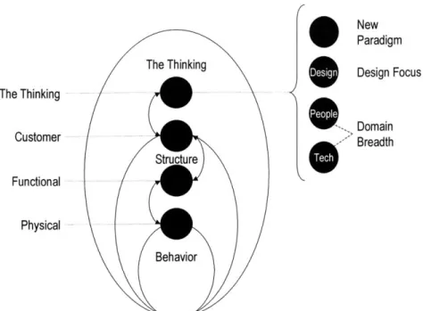
The model shown in Figure 2-5 reflects a condensation of the attributes described above into three patterns of relationship. The model shown in Figure 2-6 captures the principles of the ideal system engineering approach and distills the significance into three primary patterns of relationships know as 1) the thinking, 2) the structure, and 3) behaviors.
The Thinking
Structure
Behavior
2.4
Review of Five General Design Approaches
2.4.1 Introduction
The subsequent section starts with a review of five distinct, yet related, approaches to structural system design and their relationship to the ideal systems engineering model. Each approach draws upon a number of characteristics of system design, and the
approaches have many structural similarities (e.g. hierarchical, matrix representation, or diagraph form). However, each approach's effectiveness in system design, and
ultimately its effectiveness in an ideal systems engineering application, becomes apparent when one looks at the thinking behind the development of the approach.
2.4.2 Axiomatic Design
Developed by Suh in the 1970s, Axiomatic Design is a 'green field' (i.e. synthesis-focused) approach to designing systems. The approach defines design as the synthesis of solutions through a mapping process between four domains-customer, functional, physical, and process. Core to the development of the approach is the rejection of a major assumption in the design field-that only subjects dealing with nature (e.g. thermodynamics, geometry, physics) are subject to axiomatization [Suh, 1990].
Fundamental to Axiomatic Design is the notion of design axioms. Axioms are defined as general principles or self-evident truths that cannot be derived but for which there are no counter-examples or exceptions. The use of axioms has played a fundamental role in the advancement of many fields of science and technology. Examples of the use of axioms include Euclidean geometry, thermodynamics, Newtonian physics, and then Einstein's theory of relativity [Suh, 1990]. These fields have transitioned from experience-based practices to the use of scientific theories and methodologies that are based on axioms. The axiomatic design axioms were created by identifying common elements present in all
good designs [Suh, 1995]. The Concept of Domains
Design may be described by the continuous interplay between what we want to achieve and how we want to achieve it. Design requirements are always stated in the functional domain, whereas the solutions are always defined in the physical domain. More
formally, design may be defined as the creation of synthesized solutions that satisfy perceived needs through the mapping between the requirements in the functional domain and the solutions in the physical domain [Suh, 1990]. The mapping between the
functional and physical domain is also referred to as logical mapping. In this instance, logical refers to a mental process.
For an in depth account of use of axioms in other fields, see Suh's (1990) Principles of Design. In the book, there is also a historical account of the development of the design axioms.
The success of any system design depends on satisfying the needs of the internal and external customer. System design takes these needs and translates them into system design Functional Requirements (Figure 2-7). System design is about defining the patterns of relationship between Functional Requirements (FRs) and Design Parameters
(DPs). This approach requires defining the pattern of thought (i.e. the metaphysical) in the form of Functional Requirements and connecting Design Parameters in advance of the physical design.
What? How!
Translation Mapping
Customer Fs -A DPs
Wants s
Customer Functional Physical
Domain Domain Domain
Figure 2-7. System design connects three domains
Functional Requirements and Design Parameters
The fundamental hypothesis of Axiomatic Design is that a logical design's effectiveness can be determined in advance of the physical implementation [Suh, 2000]. The
Axiomatic Design methodology thus focuses a designer on first determining the
requirements of a design, which are stated in terms of the Functional Requirements of a design. Functional requirements are defined as the minimum set of independent
requirements, which completely characterize the functional needs of the customer, without redundancy. Functional Requirements are derived to satisfy customer's needs that characterize the customer domain.
FRs are also subject to constraints. Constraints (Cs) are defined as the limiting values, conditions, or bounds a proposed design solution must satisfy. Constraints are different from FRs in that constraints do not have to be independent from other constraints or FRs.
A designer then chooses the Design Parameters to satisfy the stated FRs. Design
parameters are the key solutions that logically satisfy the specified set of FRs. The way in which the DPs affect the FRs determines whether the design is predictable, and whether the requirements are indeed independent of each other.
By separating the functional space from the physical space, the design requirements are
defined in a solution-neutral environment without any preconceived notion of a physical solution in mind. Axiomatic Design thus guides a designer to solve a particular
Functional Requirement by the selection of a specific means (DP), rather than focusing on just the means themselves. The design process is illustrated in Figure 2-8, where DPs in the physical domain are chosen to satisfy FRs in the functional domain.
FRs DPs
1 Mapping 1
J, J
Functional Physical
space space
Figure 2-8. Representation of the mapping process [Suh, 2000]
Two Axioms and the Decomposition Process
One element of Axiomatic Design is the process of determining the DPs to satisfy the FRs. Since different logical designs can achieve the same customer needs, Axiomatic Design uses the following two axioms to select the best logical design:
Independence Axiom: Maintain the independence of the FRs through the
selection of DPs. The solution set of DPs is chosen to satisfy the FRs so that the FR implementation is independent (i.e. - one-to-one relationship, or uncoupled).
Information Axiom: Minimize the information content of the design. Simpler
designs are better than complex designs. Among alternatives, the design with the DPs that have the highest probability to meet the FRs, within tolerances, is the best.
The process of decomposition establishes a design hierarchy based upon the selection of DPs to satisfy the FRs at increasingly refined levels of detail. To advance to the next level of detail of decomposition requires the fulfillment of the Independence Axiom. Once a set of DPs has been determined at one level of decomposition, the next step is to decide if further decomposition to another level of FRs and DPs is necessary.
In Axiomatic Design, the relationships between the FRs and DPs are represented in either vector or diagraphical form. In diagraphical form, an off-axis arrow from an FR-DP pair to another FR represents the influence of that DP upon partially satisfying the other FR. The decomposition, or mapping process, is depicted in Figure 2-9 below.
FRI
DPI Design Equation
{FR}= [A] {DP}
F FR11 r
X 0' DP11
-FR12J X X DP12J
DP11 DP12
Figure 2-9. Mapping the FRs to the DPs
In vector form, the design matrix (DM) is defined as the second order tensor that relates the what vector to the how vector. In the case of product design, the Design Matrix relates FRs to DPs. The relationships between FRs and DPs constitutes [A] matrix-known as the design matrix. In the design matrix an 'X' signifies that a DPj affects FRi.
The design equation thus expresses the logical relationship between the FRs and the DPs. Five Types of Designs
Axiomatic design identifies five main types of designs: uncoupled, path dependent (partially coupled), coupled, incomplete, and redundant. These types of designs can be defined through the logical design equation.
Predictable Designs - Uncoupled and Path Dependent
Of the five types of design types, only two satisfy the Independence Axiom so that a
design is predictable-uncoupled and path dependent designs. An uncoupled design results when each FR can be satisfied independently by means of only one DP, resulting in a diagonal matrix (Equation 2-1). This design is the most robust.
FRI = X - ~ * DPI
FR}2 - - DP2
Equation 2-1. Uncoupled design
The second type of design is a path dependent design. This type of design results in a triangular matrix (Equation 2-2) and the independence of FRs can be guaranteed if the DPs are implemented in the proper (path dependent) sequence. The path dependency sequence is based on choosing the DP that affects the most FRs first, followed by the DP that affect the second-most FRs, and so on. The specific implementation sequence results in a physically implementable system design that does not require iteration to achieve the desired FRs. Within Axiomatic Design convention, the implementation sequence is graphically represented by a left-to-right ordering so that the DP that affects the most FRs is on the left.
FR, [x -_ DP
FR2 -X X _DP2
Equation 2-2. Path dependent design
Both uncoupled and partially-coupled (decoupled) designs are said to satisfy the requirement of functional independence2, as stated by the Independence Axiom.
Poor Designs - Coupled, Redundant, and Incomplete
Another form of the design matrix is called a full matrix and results in a coupled design (Equation 2-3). A coupled design violates the Independence Axiom and has a low probability of FR achievement, especially in the presence of DP variation. Such designs often require the designer to repeatedly tweak the DPs in hope of achieving the FRs. Hence, coupled designs create an unnecessary optimization problem [Suh, 2000].
{
FR, [X X ~ DP,FR2 -X X DP2
Equation 2-3. Coupled design
Two other types of less common designs are known as incomplete and redundant designs. Incomplete designs result when there are more FRs than DPs to satisfy them (Equation 2-4). The flaw with this design is that it fundamentally does not meet all the
requirements.
FRI [X - DP1
FR2 X - ~
Equation 2-4. Incomplete design
In contrast, redundant designs typically meet all the requirements but with the use of unnecessary resources (Equation 2-5). This type of design is more costly, and according to the Information Axiom is less reliable than a complete design.
{FRI [X1 *DP,
X _DP2
Equation 2-5. Redundant designSummary
The required steps for the Axiomatic Design process can therefore be summarized by Figure 2-10.
2 Functional independence should not be confused with physical integration, which is often desirable as a
consequence of Axiom 2. Physical integration without functional coupling is advantageous, since the complexity of the product is reduced.
Coupled Partially Coupled
etermination Synthesis of Evaluation Partially Selection of kfntieal oh potential design t of design od the best set
functional parameters (DPs) Matanx Uncoupled of DPs
2 re4.3 rQls to satisfy Fi R's (Axiom 1) (Axiom 2)
Do ne Yes Decomposition
<4 ? complete!
Determination No
of lower-level FR's
Figure 2-10. Simplified Axiomatic Design decomposition Process [Linck, 2001] The determination of design solutions is a creative process that requires content
knowledge of the subject. Axiomatic Design provides a methodology to structure one's thinking during the design process, and provides a logical approach to defining the
functional requirements (FRs) and the means of achievement (DPs).
2.4.3 Quality Function Deployment (QFD) - House of Quality
The focus of
Quality
Function Deployment is upon capturing the 'voice of the customer' and translating the needs into customer re iements. Fine [1998, p. 189] states that "any product whose development does not capture the voice of the customer begins life with a huge, frequently fatal handicap." Once the customer's true requirements are captured, the approach focuses on providing customers what they want. The approach is intended to focus on the customer, rather than on an organization's impulses to implement a pre-determined science or technology solution. The intention of QFD is similar to a well-known venture capitalist saying that 'products that are designed to fit customers are much more successful than customers who are designed to fit around products.'The centerpiece tool of QFD is known as the 'house of quality'-a name derived from the diagram which resembles a box with a slanted roof. The general form of the house of quality is shown in Figure 2-11.
z Roof Matrix
Engineering
Characteristics
Relationship
Matrix
Figure 2-11. House of Quality's five key elements
The house of quality is primarily described by the following five elements [Hauser, Clausing, 1988]:
- Customer Attributes (CAs): Customer's needs are called customer attributes,
or CAs. CAs are generally stated in the customers' own words and are often grouped into bundles of attributes. For example, 'quietness' might be further described by sub-categories as no wind noise, doesn't rattle, no road noise, etc. CAs typically come from the marketing domain.
- Relative Importance of CAs: Weightings, totaling 100%, are given for each CA. The motivation is two-fold. First, customers value certain attributes more
than others. This is simply the nature of customers. Secondly, the assumption is that designers will usually have to trade off one benefit against the other. The balancing of attributes will hopefully enable designers to find a creative
solution that satisfies all the customers needs, with preference given to those needs which are more heavily weighted.
- Engineering Characteristics (ECs): According to Hauser and Clausing [1988], the marketing domain communicates what needs to be done, and the
engineering domain determines how to do it. ECs translate the customers' needs into engineering requirements that describe the product in measurable, or physical, terms (e.g. seal resistance, energy to close door, noise reduction).
- Relationship Matrix: The relationship matrix represents the body of the
house. The relationship matrix indicates the relationship between ECs and ACs. Typically, these relationships are qualitative and are represented by numbers or symbols according to the strength of the AC-EC relationships.
These relationships may be determined by intuition, judgment, experiments, or even statistics. In a number of cases, an EC may affect more than one CA.
* Roof Matrix: Hauser and Clausing submit that engineering is described by
creative solutions and a balancing of objectives-the roof matrix is intended to recognize these interactions and facilitate engineering creativity. The house of quality's roof matrix establishes the relationships between ECs themselves. For example, improvement on EC1 may negatively affect EC2 but positively affect EC3. In instances such as these, Hauser and Clausing (1988, p. 7) state that
"sometimes one targeted feature impairs so many others that the team decides to leave it alone. The roof matrix facilitates necessary engineering trade-offs."
An example of a partially completed house of quality is shown in Figure 2-12.
R*Iationships V S*ongposive SMe&um posi~e K Medum negoiA, CUSTOMER ATTRIBUTES OPEN-CLOSE SEAUI-EFFORT NSULATKON I 4-- I 4- ±±i 8 o <o ex:
Eosy so cbe from outsid 7 X
Stys open on o hil 5
0 Eosy to open frcm outsido 3
%n Doesn'i kik bock 3
SDoe.sn't lok inroin 3 __
!R No road nise 2__
Figure 2-12. House of Quality [Hauser, Clausing, 1988]
The house of quality is intended helps guide designers in driving customer needs into physical requirements. The method structures the design process, and focuses the
designer on recognizing inter-dependent relationships, the importance of weightings, and making trade-offs during the design process to arrive at an acceptable solution.
quality apply to any effort to establish clear relations between manufacturing functions and customer satisfaction that are not easy to visualize." Accordingly, the principal benefit is that it gets "people thinking in the right directions and thinking together"
[Hauser, Clausing, 1988, p. 13].
2.4.4 Problem-Solving Hierarchy Mapping - Issue Trees and MECE Issue trees are just one of many tools used in a problem-solving process (Figure 2-13). Issue trees are primarily used in conjunction with idea generating activities, such as brainstorming and literature research. Issue trees focus on the structuring of ideas for
analysis and problem-solving, rather than exclusively on the traditional design process.
Where Where
the client Define the Solve Communicate the client
is problem the problem the wants to
answer be Structure the ideas Develop Generate the ideas research plan Analyze findings
Figure 2-13. Issue-based problem solving [Accenture, 2002]
In general, there are two types of issue trees-those rooted in 1) data, or 2) hypotheses. Data-driven issue trees start with the problem, and breaks it down to generate a solution. The problem/cause decomposition typically makes no assumption about the most likely outcome or most important question to answer. Rather, the data-driven trees are
constructed to answer the question of why. In contrast, hypothesis-driven trees start with the potential solution and develops a rationale to validate or disprove it. The
solution/action approach assumes an answer and creates a structure to test it. The hypothesis-driven method seeks to test the rationale of how.
Data-Driven - "Why?"
Hypothesis-Driven - "How?"
Figure 2-14. Two types of issue-based problem solving approaches [Accenture, 2002]
The key to creating a valid issue tree is to ensure the logical soundness of the decomposition through mutual exclusivity and collective exhaustiveness (MECE). Mutual exclusivity means that the occurrence/existence of events/solutions are independent of each other. Collective exhaustiveness means that the entire set of events/solutions have been defined. The decomposition process involves ensuring the following four elements have been achieved [Accenture, 2002]:
- Logic is complete at every level
- Elements at any level are logically part of the level above
- All possible elements at a level are included at the level below
- Elements in any grouping are the same kind of thing
An illustration of a data-driven tree is show in Figure 2-15. This data tree might be used to perform an analysis of a given problem at hand.
Problem/ - - Case Issue -L as Reason/ * *u a __ RAston/ Potetial Reason/ SolutionAction
Problem/issue Should we pursue the 1st time buyer market in PCs? Sub-issues
Will 1st time buyers be profitable for us?
Is a 1st time buyer - strategy aligned with
corporate strategy?
- Revenue potential?
- Costs to serve?
Aligned with brand image?
Keeps us competitive? Matches our target segments?
ISub-sub-issues
Total market size? Our likely market share? Incremental sales and marketing costs? Incremental operational costs?
Differentiates us in the marketplace? Brings us to parity with competitors?
Figure 2-15. Illustration of a data-driven tree for analysis [Accenture, 2002]
From a design perspective, a hypothesis-driven tree looks may look very similar to a Bill-Of-Materials (BOM). Similar to a BOM, the hypothesis-driven tree focuses on defining a high-level how and determining lower-level reasons/actions. These decomposition methods disaggregate larger problems/hypotheses into smaller, defined physical chunks. The logic behind this dis-aggregation process is mainly driven by the logic of the MECE test. Intake Manifold Assembly Machined Casting - Manifold Piin
- EGR Return Pipe
End fittings PCV assembly Related Components Vacuum source block assembly Valve Gasket Cover Screws Block Gasket Screw
2.4.5 Design Structure Matrix (DSM)
The Design Structure Matrix (DSM) is described as a tool for systems analysis and project management. The DSM is also known as the Dependency Structure Matrix, the Problem Solving Matrix, and the Design Precedence Matrix. The DSM primary
effectiveness is by means of representing and analyzing task interactions,
interdependencies, and interfaces between system elements (i.e. sub-systems and modules). The DSM also provides for representation of feedback and cyclic task dependencies-a feature that allows for project representation [Eppinger, 2001].
The use of matrices in system analysis and management can be traced back to Warfield
[1973] and Steward [1981]. More recently, the DSM has been applied to industrial
project planning and development projects at the task level [Eppinger, 1994]. The DSM method recognizes three types of basic task dependencies: parallel (or concurrent), sequential (or dependent) and coupled (or interdependent). Tasks are represented by boxes and information (data) dependencies are represented by arrows-an information processing view of product development (Figure 2-17).
Relationship Parallel Sequential Coupled
A A
Graph -i-IL]
Representation B B
Figure 2-17. Diagraphs of three basic types of task dependencies [Ulrich, Eppinger, 2000].
Of the three tasks, parallel relationships are not dependent on the output of another task.
Rather, parallel tasks are dependent on the same task (i.e. the task beforehand) but are independent of each other. In this instance, understanding the behavior of the individual elements enables complete understanding of the system [Eppinger, 2001]. Thus, no information exchange is required between the two activities. In contrast, sequential tasks are dependent upon the previous task's completion. Thus, one element's influences the behavior of another element in a unidirectional manner. Coupled tasks are mutually dependent, or intertwined. According to Ulrich and Eppinger, coupled tasks "must either be executed simultaneously with continual exchanges or information or must be carried out in an iterative fashion [Ulrich and Eppinger, 2000, p. 324]." This cyclic dependency is referred to as "circuits" or "information cycles" [Eppinger, 2001].
The Design Structure Matrix is a matrix representation of a diagraph that is a binary square matrix with m rows and columns, and n non-zero elements, where m is the number of nodes and n is the number of edges in the diagraph [Eppinger, 2001]. The DSM is constituted of two major elements: a row and column of m tasks, and a matrix of mxm dependencies. Project tasks are defined by a row of the matrix. Reading across a row signifies all the tasks whose output is required to perform the task corresponding to the
row. Reading down a column indicates which tasks receive information from the task corresponding to the column. Sequentially dependent, and parallel tasks are represented
by a lower-triangular matrix, whereas marks appearing above the matrix diagonal signify
coupled tasks (Figure 2-18). Marks below the matrix diagonal represent forward information flow (i.e. feed-forward) to later tasks, whereas, marks above the matrix diagonal represent information fed back (i.e. feedback or coupled) to earlier listed tasks. According to Eppinger [2001], "in the binary matrix representation of a system, the diagonal elements of a matrix do not have any interpretation in describing the system."
Task A B C D E F G H I J K L M N Figure 2-18. Example of a A S X B T X X C
X
X D'-X D'-X D'-X X X X X X X X A B C D E F G H I J K L M N equential asks Pe ~~ Tasksrallel E Coupled Tasks X F X G X X XH X X X I X X X J X X X X K X L X M X X X Ndesign structure matrix [Ulrich, Eppinger, 2000]
The DSM can be used to "optimize information flows" using four methods [Eppinger, 2001]:
- Sequencing and Partitioning: These two approaches do not materially affect
the task constituents of the organization. Changing the order of tasks can be done by two methods known as sequencing and partitioning. These two methods are meant to create as independent of a matrix as possible (e.g. lower-triangular). The key objective of these methods is to minimize the number of
information feedbacks above the diagonal. This is matrix reorganization is done by concurrently sequencing and partitioning the tasks-1) find tasks that can be scheduled early or late, and 2) then group the remaining tasks into (coupled) blocks that bring the X's as close to the diagonal as possible. The goal of partitioning the matrix is to identify, separate, and then manage coupled tasks.
![Figure 2-10. Simplified Axiomatic Design decomposition Process [Linck, 2001]](https://thumb-eu.123doks.com/thumbv2/123doknet/14456415.519706/29.918.128.766.106.345/figure-simplified-axiomatic-design-decomposition-process-linck.webp)
![Figure 2-12. House of Quality [Hauser, Clausing, 1988]](https://thumb-eu.123doks.com/thumbv2/123doknet/14456415.519706/31.918.216.707.404.960/figure-house-quality-hauser-clausing.webp)
![Figure 2-15. Illustration of a data-driven tree for analysis [Accenture, 2002]](https://thumb-eu.123doks.com/thumbv2/123doknet/14456415.519706/34.918.164.730.95.393/figure-illustration-data-driven-tree-analysis-accenture.webp)
![Figure 2-23. Development cycle for Axiomatic Design vs. Build-Test-Fix [Adapted from Suh, 2002]](https://thumb-eu.123doks.com/thumbv2/123doknet/14456415.519706/44.918.176.752.123.451/figure-development-cycle-axiomatic-design-build-test-adapted.webp)