by
Daniel Shawn Codd
M.S. Mechanical Engineering
Stanford University, 1999 B.S. Mechanical Engineering University of California, San Diego, 1997SSACHUSETTS INSTITUTE
OF TECHNOLOGY
AUG 0
3
2011
LIBRARIES
ARCHIVES
SUBMITTED TO THE DEPARTMENT OF MECHANICAL ENGINEERING IN PARTIAL FULFILLMENT OF THE REQUIREMENTS FOR THE DEGREE OF
DOCTORATE OF PHILOSOPHY AT THE
MASSACHUSETTS INSTITUTE OF TECHNOLOGY JUNE 2011
@ 2011 Massachusetts Institute of Technology All rights reserved
Signature of A uthor...
Department of Mechanical Engineering April 26, 2011
Certified by... ...
Alexander H. Slocum Pappalardo Professor of Mechanical Engineering MacVicar Faculty Fellow Thesis Supervisor
Accepted by... ...-. 7..n.:... Professor David E. Hardt Chairman, Department Committee on Graduate Students
by
Daniel Shawn Codd
Submitted to the Department of Mechanical Engineering on April 26, 2011 in Partial Fulfillment of the Requirements for the Degree of Doctorate of Philosophy in
Mechanical Engineering
Abstract
This thesis describes a new concentrating solar power central receiver system with integral thermal storage. Hillside mounted heliostats direct sunlight into a volumetric absorption molten salt pool, which also functions as a single tank assisted thermocline storage system. Concentrated light penetrates the molten salt and is absorbed over a depth of several meters; the molten salt free surface tolerates high irradiance levels, yet remains insensitive to the passage of clouds. Thermal losses to the environment are reduced with a refractory-lined domed roof and a small, closeable aperture. The molten salt and cover provide high and low temperature heat sources that can be optimally used to maximize energy production throughout the day, even when the sun is not shining. Hot salt is extracted from the upper region of the tank and sent through a steam generator, then returned to the bottom of the tank. An insulated barrier plate is positioned vertically within the tank to enhance the natural thermocline which forms and maintain hot and cold salt volumes required for operation. As a result, continuous, high temperature heat extraction is possible even as the average temperature of the salt is declining.
Experimental results are presented for sodium-potassium nitrate salt volumetric receivers optically heated with a 10.5 kilowatt, 60-sun solar simulator. Designs, construction details and performance models used to estimate efficiency are presented for megawatt-scale molten salt volumetric receivers capable of operating with low cost nitrate or chloride salt eutectics at temperatures approaching 600 'C and 1000 'C, respectively. The integral storage capabilities of the receiver can be sized according to local needs, thereby enabling power generation on demand.
Thesis Supervisor: Alexander H. Slocum
A bstract ... 3
List of Figures...6
List of T ables ... 9
N om enclature... 10
A cknow ledgm ents...13
C H A PT E R 1: Introduction...17
Solar Therm al Pow er...19
O bjectives... 34
C H A PT E R 2: The C SPonD C oncept ... 37
H illside heliostats ... 44
V olum etric receiver pond...46
Integral D ivided Therm ocline Storage ... 55
M aterials selection... 67
C H A PT E R 3: C SPonD Perform ance...77
Receiver heating and efficiency analysis ... 79
O perational issues... 99
E conom ics ... 110
C H A PT E R 4: E xperim ental T esting ... 115
Single tank volum etric receiver...117
D ivider plate equipped receiver... ... ... 121
A ctive flow receiver...126
C H A PT E R 5: Idealized C SPonD System D esign ... 147
C H A PT E R 6: C oncluding R em arks ... 179
Future w ork ... 185
A PPE N D IX - Solar Sim ulator D esign ... 187
R eferences ... 207
Figure 1.1 -Solar pow er: PV vs. CSP ... 20
Figure 1.2 -CSP collection technologies...21
Figure 1.3 -C entral receiver designs... 25
Figure 1.4 -HTF flow and temperature profiles in conventional receivers ... 25
Figure 1.5 -Molten salt waterfall Direct Absorption Receiver (DAR) concept...27
Figure 1.6 -Beam down system with ground level molten salt receiver concept ... 29
Figure 1.7 -Odeillo 1 MWe solar furnace utilizing hillside heliostats ... 30
Figure 1.8 -Divided single tank molten salt thermal storage concepts... 34
Figure 2.1 -CSPonD beam down system architecture... 40
Figure 2.2 -Initial CSPonD system concept ... ... ... 43
Figure 2.3 -Representative hillside CSPonD sites in White Sands, NM... 45
Figure 2.4 -CSPonD receiver cutaway view ... 47
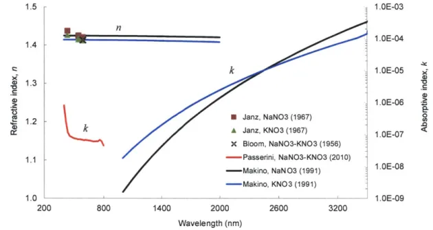
Figure 2.5 -The complex index of refraction for molten nitrate salts... 49
Figure 2.6 -Solar irradiance attenuation for various molten salt depths ... 49
Figure 2.7 -Volum etric absorber heating profile ... 53
Figure 2.8 -CSPonD storage system at various states of charge ... 56
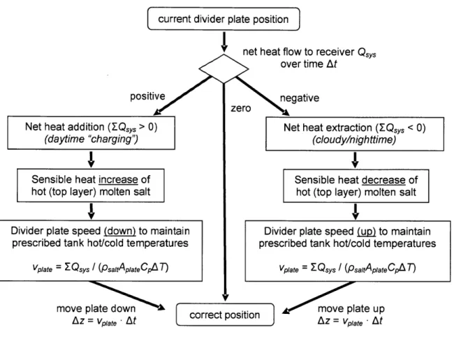
Figure 2.9 -Schematic of divider plate motion during charging... 58
Figure 2.10 -D esign process for divider plate gap... ... ... 60
Figure 2.11 -Position control strategy for divider plate... 62
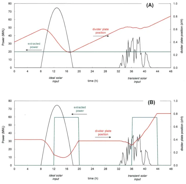
Figure 2.12 -Simplified divider plate positioning example for two day/night cycles ... 63
Figure 2.13 -W eir hot salt heat extraction schem e ... ... ... 66
Figure 2.14 -Open air NaCl-KCl salt bath at 900 'C for metal heat treating ... 68
Figure 2.15 -Side draft fume hood used to collect salt vapors ... 73
Figure 2.16 -Tank w all insulation schem atic ... 74
Figure 3.1 -Reflection coefficient for various beam down angles ... 80
Figure 3.2 -Irradiance distribution within CSPonD receiver... ... 81
Figure 3.3 -Simplified CSPonD DAR geometry and energy balance diagram...82
Figure 3.4 -Schematic of CSPonD receiver "capture efficiency" calculation ... 83
Figure 3.5 -CSPonD D A R capture efficiency...88
Figure 3.6 -Exergetic capture efficiency of CSPonD receiver... 89
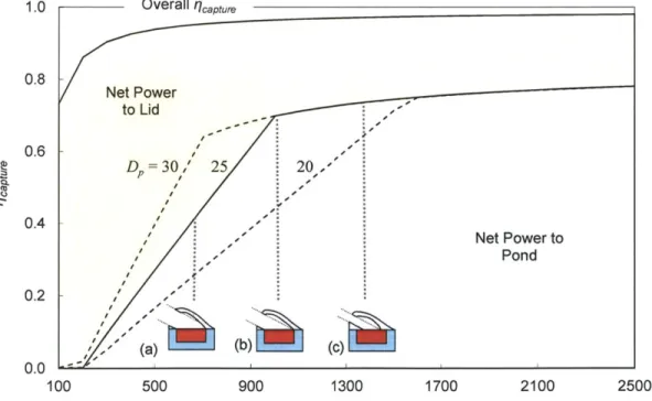
Figure 3.7 -Effect of pond diameter on capture efficiency... 90
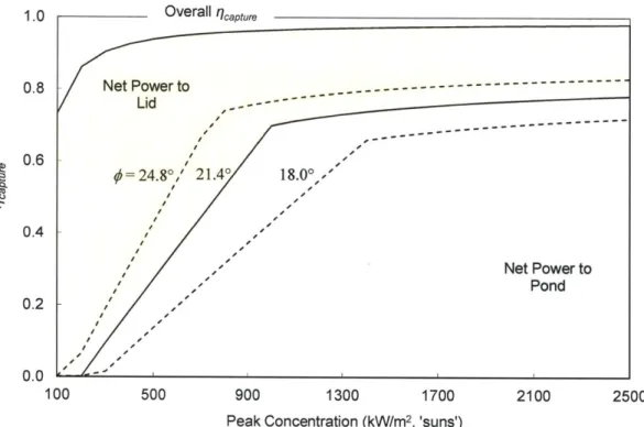
Figure 3.8 -Effect of beam down angle on capture efficiency ... 92
Figure 3.9 - Effect of lid internal temperature on capture efficiency... 93
Figure 3.10 -Integrated concentration booster geometry in lid reduces exposed salt area...93
Figure 3.11 -On sun lid temperature for various lid heat extraction percentages ... 95
Figure 3.12 -Lid temperature maps as a function of salt temperature while on sun... 96
Figure 3.13 -Lid temperature maps for a beam up system on sun ... 97
Figure 3.14 -Lid temperatures for a highly reflective lid beam up system on sun ... 98
Figure 4.1 -Schem atic of single tank test receiver ... 118
Figure 4.2 -Solar Simulator with single tank volumetric receiver at aperture. ... 118
Figure 4.3 -Molten nitrate solar salt mixture in single tank test receiver ... 119
Figure 4.4 -Temperature distribution of nitrate salt mixture in single tank test receiver...120
Figure 4.5 -Volumetric versus surface heating temperature profiles...121
Figure 4.6 -Schematic of movable divider plate test receiver ... 122
Figure 4.7 -Molten nitrate solar salt in movable divider plate test receiver...123
Figure 4.8 -Temperature distribution of nitrate salt in divider plate test receiver...124
Figure 4.9 -Heat transfer regimes for hot nitrate salt layer above divider plate ... 126
Figure 4.10 -Schematic of active flow thermosiphon test receiver...127
Figure 4.11 -Active flow test receiver construction details ... 128
Figure 4.12 -Temperature evolution in thermosiphon system: water ... 130
Figure 4.13 -Divider plate temperature in thermosiphon system: water ... 130
Figure 4.14 -Temperature evolution in non-insulated thermosiphon system: water...131
Figure 4.15 -Temperature profile within active flow test receiver: water...132
Figure 4.16 -Active flow test receiver for use with molten nitrate solar salt...133
Figure 4.17 -Temperature evolution in thermosiphon system: nitrate salt...134
Figure 4.18 -Temperature profile within active flow test receiver: nitrate salt ... 135
Figure 4.19 -Flow visualization in reservoir of active flow test receiver: water...137
Figure 4.20 -Infrared flow visualization in reservoir of active flow test receiver: nitrate salt ... 137
Figure 4.21 -Quartz aperture window appearance on active flow test receiver...138
Figure 4.22 -Appearance of unmelted solar salt used in tests ... 141
Figure 4.23 -Solid salt temperature during heating with solar simulator ... 142
Figure 4.24 -Virgin melted solar salt with foamy surface scum ... 143
Figure 4.25 -Solidified pure and surface scum salt samples...143
Figure 4.26 -X -ray diffraction data for pure solar salt ... 145
Figure 4.27 -X-ray diffraction data for brownish surface solar salt scum ... 145
Figure 5.1 - Idealized hillside field: 813 heliostats, top view...150
Figure 5.2 - Idealized hillside field: 813 heliostats, side view...150
Figure 5.3 -Peak intensities at aperture for idealized heliostat field... 152
Figure 5.4 -Directional distribution of flux at the aperture origin: top view...153
Figure 5.5 -Directional distribution of flux at the aperture origin: side view...153
Figure 5.6 - Cumulative flux distribution projected on aperture plane...154
Figure 5.7 -Net energy flow into receiver for various aperture sizes ... 157
Figure 5.8 -D ivider plate therm al resistance circuit...160
Figure 5.9 -T ank w all tem perature profile ... 163
Figure 5.10 -Lid tem perature profile ... 166
Figure 5.11 -Temperature drop in molten salt at tank wall interface ... 166
Figure 5.12 -Year-round cosine efficiency at solar noon ... 173
Figure 5.16 -View facing CPC entrance aperture ... 175
Figure 5.17 -Exploded view of CSPonD receiver ... 176
Figure 5.18 -Tank and divider plate cross-section detail...177
Figure 5.19 -Typical tank wall insulation details ... 177
Figure 5.20 -Scale of receiver w.r.t. heliostat field area...178
Figure 6.1 -D esign parallels for the CSPonD system ... 184
Figure A. 1 -M IT m etal-halide CSP solar sim ulator...190
Figure A.2 -Lum inous intensity distribution for various M H reflectors ... 192
Figure A.3 -Simulator support fram e...194
Figure A.4 -Rotation adjustm ent plate ... 195
Figure A.5 -Flow-Line Concentrator geom etry ... 196
Figure A.6 -O utput aperture flux ray tracing results...196
Figure A.7 -Secondary concentrator structure ... 197
Figure A.8 -Spectral intensity com parison for the M IT CSP simulator...199
Figure A.9 -Calorim etric absorber target tem perature...200
Figure A.10 -H eat flux balance for top surface of horizontal absorber test target...201
Figure A. 11 - Calculated aperture flux distribution...205
Table 2.1 -Representative metallurgical heat treatment salts appropriate for CSPonD...69
Table 3.1 -Nominal CSPonD design values for capture efficiency analysis...87
Table 3.2 -CSPonD risks and counterm easures...101
Table 3.3 -Therm al properties of solid salt m edia...105
Table 3.4 -Maximum allowable flux and peak temperature overshoot during melting...109
Table 3.5 -Sensible heat thermal energy storage media costs ... 111
Table 3.6 -Upper and lower bounds for predicted CSPonD levelized cost of energy...113
Table 5.1 -Idealized heliostat field site param eters...149
Table 5.2 -Idealized CSPonD receiver parameters...156
T able 5.3 -T ank w all m aterials ... ... 163
T able 5.4 -Lid construction m aterials ... 165
Table 5.5 -Comparison of central receiver CSP performance...171
Table A. 1 -Solar simulator functional requirements & design specifications ... 190
T able A .2 -A bsorber disc properties ... ... .... ... 203
T able A .3 -Calculation of output flux levels...204
Abbreviations:
CPC Compound Parabolic Concentrator CSP Concentrating Solar Power
CSPonD Concentrated Solar Power on Demand DAR Direct Absorption Receiver
DNI Direct Normal Irradiance FLC Flow Line Concentrator HTE Heat Transfer Equation HTF Heat Transfer Fluid IFB Insulating Firebrick
NREL National Renewable Energy Laboratory RTE Radiative Transfer Equation
Greek symbols:
a absorptivity a' thermal diffusivity
#6
attenuation coefficient#'
coefficient of volumetric expansion y rate of salt vaporization per unit area 9 optical thicknessA change of quantity 6 emissivity
q efficiency
0
angle, non-dimensional temperatureK absorption coefficient
wavelength
v kinematic viscosity
tank (conduction) storage efficiency p reflectivity, density
0- Stefan-Boltzmann constant
os scattering coefficient $ beam-down angle
<0 flux: solar radiation per unit area 4D;* spectral scattering phase function X exergetic efficiency
A area
c, specific heat
C concentration ratio
D diameter
F12 view factor from surface 1 to surface 2
g gravitational acceleration
h convection coefficient
H height, depth
AH,,ap enthalpy of vaporization of salt
i -1
I intensity
h spectral irradiance
k absorptive index, thermal conductivity I penetration depth
L characteristic length, latent heat of fusion
m complex index of refraction
n refractive index
P power
P pressure
r range distance
R reflection coefficient, thermal resistance Ra Rayleigh number
Ri Richardson number Ste Stefan number
t time
T temperature
v velocity
V absorber volume
q heat flux
Q
heat flow rateSubscripts: spectral a aperture b blackbody c cold conv convective cos cosine crit critical decomp decomposition
div divider plate
e electric
ele parasitic electrical
hx heat exchanger/steam generator i incident in input ip illuminated pond ir infrared / lid
1-a lid to aperture
m mean melt melting max maximum opt optical os overshoot p nominal/design pond
p-a pond to aperture
p-i pond to lid
r reflected rad radiative rec receiver solid solidified sys system t thermal, transmitted vap vaporization vis visible 0 initial oc ambient
"That's it! You people have stood in my way long enough. I'm going to clown college!"
-Homer Simpson
Initial support was provided by The Cyprus Institute, led by Prof. C.N. Papanicolas in Nicosia, Cyprus, for the Cogeneration of Electricity & Desalinated Sea Water using Concentrated
Solar Power (CSP-DSW) study. This project was part of an interdisciplinary collaboration between The Cyprus Institute, Prof. John G. Georgiadis' group at the University of Illinois at Urbana-Champaign, the Electricity Authority of Cyprus and the Massachusetts Institute of
Technology. The Chesonis Family Foundation provided generous funding through the MIT Energy Initiative for continuing research during the 2010-2011 academic year.
The work described in this dissertation would not have been possible without guidance and support from numerous individuals and institutions. I would like to thank my magnanimous advisor, committee chair and the CSPonD project Principal Investigator, Prof. Alex Slocum, for giving me the opportunity to contribute to a really hot and timely topic. Thanks, dude!
I'd also like to thank my cellmates in the Precision Engineering Research Group for creating an awesome lab environment, providing technical support, laughter and distractions all while juggling interesting projects of their own. Special thanks to PERGies Danielle, Nevan, Zac
& Conor. I would like to acknowledge all the members of the MIT CSPonD team and associated student researchers, all of whom I gratefully acknowledge here with my sincere thanks:
Faculty and research staff:
J. Buongiorno, C. Forsberg, T. McKrell, A. Mitsos, J.C. Nave, A. Slocum (PI) Postdoctoral researcher:
A. Ghobeity Graduate students:
A. Lenert, C. Noone, S. Passerini, F. Rojas, V. Somani, C. Williams Undergraduates:
A. Adames, J.R. Alvarado, A. Carlson, A. Paxson, J. Rees
I would also like to thank Prof. Alexander Mitsos and Prof. Ronald Ballinger for serving on my thesis committee and providing valuable insight and constructive critique
throughout the duration of the project. Thanks to Dr. Tom McKrell and the NS&E Green Lab for housing the solar simulator. John Barry, President of Ajax Electric Co., PA; John and Kevin O'Meara, President and Manager of Metallurgical Solutions, Inc. RI and Dr. Stephen Fantone, President and CEO of Optikos Corp., MA, all provided much needed practical industrial wisdom regarding molten salt bath furnaces and optics. Additionally, I wish to thank Prof. Jacob Karni of the Weizmann Institute and Dr. Robert Copeland, formerly of the Solar Energy Research Institute (now NREL), for graciously sharing solar power receiver and thermal storage design experiences and lessons learned. I would also like to thank Dr. Aris Bonanos and Dr. George Tzamis for their technical contributions to the CSP-DSW study and hospitality showing me around Cyprus.
And of course, I'd like to thank my parents, sister, and my niece and nephews for their prayers and encouragement along the way.
Cambridge, Massachusetts, in April 2011
whose sunbathing skills would have put
the world's best solar power collection systems to shame... R.IP. 1918-2010.
Motivation
Solar thermal power technologies offer much promise for satisfying global energy needs and can be used for "clean" power generation - but current solutions fail to be widely
implemented due to their relative inefficiencies and high costs. Nevertheless, Concentrating Solar Power (CSP) is still considered one -of the most promising technologies for large scale renewable power generation. In the southwestern United States alone, 45 CSP projects exceeding 11 GWe are planned for development [1]. However, conventional designs are at best modestly efficient and resource intensive resulting in levelized costs of energy far exceeding fossil-powered plants. Widespread adoption to achieve aggressive goals, such as California's 33% Renewable Portfolio Standard prescribing 15-20 GWe of renewable energy by 2020, will require advanced technology development and rapid deployment.
Solar Thermal Power
CSP technologies
A robust renewable energy portfolio is likely to include systems that enable energy storage with electricity production when there is limited sunlight. Conventional photovoltaic panels convert direct and diffuse sunlight into direct-current electricity, which can be inverted into alternating-current line voltages and frequencies (Fig. 1.1). However, instantaneous electrical output is directly related to the instantaneous sunlight, or solar insolation, striking the
photovoltaic panel. Currently, storage of electrical energy for later use is costly and impractical at larger scales. In contrast, CSP systems use reflective or refractive optics to focus incoming direct sunlight onto an absorber. This absorber, or receiver, can achieve high temperatures and heat can be extracted for industrial or chemical processes, or to drive a heat engine and generate
mechanical or electrical power. Energy storage is simplified by the use of sensible, latent or chemical heat storage means. CSP with thermal energy storage has the potential to produce
around-the-clock baseload power, or meet peak electric power demands, irrespective of instantaneous solar fluctuations.
Conventional high temperature CSP systems have evolved to utilize a central power tower, whereby mirrored heliostats focus sunlight on a receiver placed atop a tower, designed to reduce heliostat shadowing and increase optical efficiency. Point-focus systems can achieve high optical concentrations, typically greater than 600 'suns' (1 sun = 1 kW/m2), resulting in high
receiver temperatures and improved power cycle efficiencies relative to line-focus (e.g., parabolic trough, linear Fresnel) or non-concentrating solar collectors [2]. Central receiver systems allow for large, more efficient, centralized power conversion equipment and simplified thermal storage as compared to small distributed parabolic dish units (Fig. 1.2).
Photovoltaic
Concentrating
TPV)
Solar Power
(CSP)
semiconductor mirror receiverTh
Vdc4Qpower
e-cycle
Figure 1.2 -CSP collection technologies
(courtesy E. Blanco, PSA)
CSP Receiver designs
There are numerous CSP receiver designs in the realm of point focus solar power towers, each attempting to address the functional requirements of capturing and converting concentrated sunlight into usable, high temperature heat. Receiver collection efficiency can be defined as the ratio of collected energy to incident energy, and ranges from 0.72-0.90 [2], [3]. Collection inefficiencies include surface reflection losses of the incident concentrated solar flux, radiative, convective, and conductive losses to the surrounding environment, and parasitic pumping power requirements for active heat transfer fluid (HTF) flow within the receiver. For an ideal absorber of concentrated solar flux, an upper bound to the collection efficiency qrec can found as [4], [5]:
collected energy = a -(1
where the receiver's absorptance and emittance are denoted by a and e, respectively, <o is the incoming solar radiation, C is the optical concentration ratio and o is the Stefan-Boltzmann constant.
In general, collection efficiency improves as receiver surface temperature, Trec, and effective emissivity (e'= e/C) decreases, favoring designs which can tolerate high flux collection and whose geometry approaches that of an ideal black-body absorber [4]. Physical systems have additional convective and conductive losses that can be minimized by increasing concentration, thereby reducing exposed surface area and insulating the receiver. Surface-receiver reflection losses can be minimized by applying high absorptivity coatings to receiver surfaces, tuned to be highly absorbing in the visible spectrum and having low emissivity in the infrared spectrum. However, Kirchhoff's law must hold true (i.e., for every wavelength a; = e;,) and as receiver temperature increases, the emissive power spectrum shifts towards lower wavelengths and the net "spectral selectivity" decreases. However, high HTF temperatures result in improved power cycle efficiency, which is limited by Carnot efficiency t
h calculated as:
useful work output _ W T (1.2)
heat from receiver Qrec Trec
where W is the work done by the power cycle, Qrec is the heat supplied to the power conversion cycle by the receiver and T, is the ambient temperature. Equation (1.2) provides a theoretical upper bound to the power cycle efficiency; real systems are subject to losses and irreversibilities and the resulting power cycle efficiency is reduced, particularly as the rated unit size decreases.
Overall solar-to-electric system efficiency, 'isolar-electric, can be found as the product of
individual efficiencies:
where, r,'k is the optical efficiency, a function of collector (heliostat field) geometry, mirror reflectivity, cleanliness and shape, and qele is the electrical conversion efficiency, which includes
conversion and parasitic power consumption losses. It can be seen from Equations (1.1) to (1.3) that high receiver efficiencies require low operating temperatures; however this results in low power cycle and overall system efficiencies. Low solar-to-electric efficiencies require more heliostat collection area, increasing capital costs and subsequent levelized costs of energy that the
CSP plant produces.
Conventional receiver designs
Conventional surface absorption tube-based receivers have been studied and tested, only to exhibit low capture efficiencies, parasitic fluid pumping losses and raise long term durability concerns [2], [6], [7]. Tubular receiver designs circulate a heat transfer fluid through an array of tubes onto which concentrated sunlight is focused (Fig. 1.3a & 1.3b). As a result, the highest temperature of the receiver is the tube's exterior surface, which must conduct the heat inwards to the colder, flowing heat transfer fluid (Fig. 1.4a). Daily and instantaneous solar variations create large temperature gradients, thermal strains and high temperature creep which all must be mitigated to avoid low-cycle fatigue failures of the tubing. Consequentially, maximum allowable flux values are limited to avoid thermal degradation of the receiver tubing [8]. Lata et al. cites the tradeoffs between tube diameter, wall thickness, receiver durability and pressure drop in
conventional tubular receiver designs while describing a "new" external tubular receiver capable of achieving slightly higher maximum fluxes, up to 1.0 MW/m2, thereby reducing receiver
surface area and losses while increasing overall plant efficiency [9].
Volumetric absorption can reduce radiative and convective losses to the environment while increasing HTF operating temperature and capture efficiency [10]. Figure 1.3c depicts a typical volumetric air receiver [11]. Volumetric absorption reduces the susceptibility of receiver or HTF overheating and failure due to transient solar fluctuations. Ideal volumetric receivers have
a peak temperature located within the HTF that is hotter than the receiver surface temperature, reducing radiative losses, as shown in Fig. 1.4b.
Receivers can be utilized with efficient north heliostat fields (in the northern hemisphere) in cavity or directional designs, whereby a concave receiving surface can be used to reduce convective and radiative losses at the expense of the receiver's acceptance angle (Fig. 1.3a & 1.3c). Alternatively, an external receiver presents a constant area target for heliostats, regardless of azimuthal position (Fig. 1.3b). However, a full 3600 circular field is non-optimal, as heliostats south of the receiver suffer from poor optical (cosine) efficiencies. As a result, the southern perimeter of an external receiver experiences reduced concentrated flux relative to the northern side of the receiver, and is typically used for HTF preheating [7], [9].
Unfortunately, both surface and volumetric receiver designs are subject to surface reflection losses. Incoming concentrated flux is reflected, directly and diffusely, away from the receiver surface and back into the environment. Conventional cavity (Fig. 1.3a) and external (Fig.
1.3b) tube-based receivers, such as those used in the PSI 0, PS20 and Solar I and II CSP test sites, respectively, are designed so that incoming flux strikes the tube near-normally to its surface. A fraction of the incident light is reflected off the receiver's surface and cannot be recaptured. Much effort and costs are spent applying spectrally selective solar absorption coatings, or relying on surface oxides to grow and reduce the tube's reflectivity - but the absorptivity of the tube surface presents an upper bound to tube-based receiver efficiency. Similarly, conventional volumetric absorption receivers rely on quartz aperture windows to isolate the HTF from the environment. Even with advanced conical aperture windows (as shown in Fig. 1.3c) designed to reduce surface reflection losses, a portion of the incident flux is returned to the environment. Additionally, aperture windows will absorb some of the incident energy throughout the solar spectrum, and completely block the small but non-zero contribution in near infrared portion for which quartz
and sapphire are opaque. Perhaps more significantly, large aperture windows are costly, fragile components and require active cooling in high-concentration systems.
r
/
(B)
Figure 1.3 - Central receiver designs From [2], [6], [7], [11]
(A)
concentrated
sunlight
losses
opaque
tube wall
Surface
absorption
(B)
concentrated
sunlight
losses
T,transparent
aperture window
Volumetric
absorption
Figure 1.4 -HTF flow and temperature profiles in conventional receivers
Heat transfer fluid
The design of a receiver depends significantly upon the choice of HTF. Working
temperatures, system sizing, materials compatibility, ease of energy transfer, toxicity and cost are key parameters used to select fluids. Materials besides fluids can be used as the primary heat transfer "fluid" within the receiver, including fluidized particle beds which transfer heat to a working HTF [5]. Some receivers are designed as high temperature chemical reactors, whereby the working fluids are the reactants and products themselves [10]. Typical HTFs include water/steam, air, molten salts (also known as fused salts) and liquid metals [12].
Early central receiver solar thermal power plants were designed with closed-loop direct steam generation receivers, creating pressurized steam fed directly into a power cycle. The receiver simply acted as a solar-powered boiler for a conventional Rankine power cycle [3]. Volumetric absorbers have been designed to heat air, typically as part of a solar-assisted gas turbine (i.e., Brayton) power cycle [11]. However, hot steam and air are low density fluids and subsequent thermal storage dictates energy transfer to a more efficient storage medium [13], [14]. Heat exchangers are needed each time energy is transferred to a new medium, increasing system cost and complexity.
Utilizing molten salts as the working fluid enables simple subsequent thermal storage, due to their high heat capacities and wide operating temperatures. Tube-based receiver designs have migrated to using molten salt as the primary HTF and storage medium [6], [9], [14]. While molten salts possess ideal heat transfer properties, relatively low viscosities and low costs, they
can freeze. The binary sodium-potassium nitrate "solar salt" mixture (60-40 wt.%), which has seen widespread adoption in central receiver CSP plants, has a freezing temperature of 222 'C [6]. Molten salt can be kept circulating in the receiver piping throughout the night, or the receiver can be drained as the sun is setting. Unfortunately, both methods require ancillary heaters and present additional risks should the salt freeze, requiring electric heat tracing on long piping runs,
valves and manifolds. Despite these measures, operating problems still occur; for example, the Solar Two CSP demonstration plant was disabled by frozen salt in pipes and clogged preheater manifolds during the daily filling process [6].
Alternative receiver designs
An alternative approach to volumetric absorption, initially proposed by Sandia in 1974, utilizes a cascading molten salt waterfall in a Direct Absorption Receiver (DAR), as shown in Fig. 1.5 [15-19]. A portion of the concentrated flux is absorbed within the salt film, and the remainder is absorbed on a darkened alloy sheet that supports the salt film, effectively
transferring thermal energy into the salt. Experiments using centimeter-thick molten salt waterfall films were found to be marginally absorbing to incoming sunlight, and the salt was doped with high absorptivity particles to collect the required energy within the salt film [15]. Unfortunately, the exposed active fluid flow, surface reflection losses, film instabilities, variations in output HTF
Support surface Collection manifold Receiver support tower
Figure 1.5 -Molten salt waterfall Direct Absorption Receiver (DAR) concept From [16]
temperature as a function of varying solar flux, and the cost of pumps, manifold and piping preheaters limits the practicality of such systems [20].
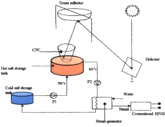
Additional receiver designs are possible if the traditional power tower approach is abandoned. Beam down systems, as originally proposed by Rabl in 1976, seek to relocate the receiver to ground level to avoid some of the tower-based receiver constraints [21]. To achieve this configuration, a secondary reflector is positioned atop a tower which redirects concentrated light from the heliostat field to the receiver. Typical Cassegrain optical geometry is employed, utilizing a hyperbolic secondary mirror. Heliostats aim at the (virtual) upper focus, above the
secondary reflector, and the receiver is placed at the lower focal point. A ground-level receiver enables the use of novel materials and geometries for receiving concentrated sunlight-notably a liquid free surface (Fig. 1.6) [22], [23]. Similarly, Yogev [23] and Epstein [24], [25] suggested a beam down system where the light was to be beamed into the central region of a metallic annulus, whereby molten salt or molten metal flows and is heated in the outer annular region. Since Rabl's proposal in 1976, significant experimental work has occurred on beam down towers and ground receivers, especially for reforming materials [22], [26].
However, beam down optics are costly, incur additional reflection losses and pose high-flux durability issues. The maximum high-flux impinged on the secondary mirror is typically limited to 35 kW/m2 to avoid active cooling and optical degradation, which dictates a relatively large mirror
area [27]. A tower still needs to be constructed, and it may shade a significant portion of the heliostat field. Tertiary concentrators are needed to compensate for the increased sun spot size due to the increased focal length created by the beam-down geometry. Non-imaging optics are used as tertiary concentrators to increase flux levels at the receiver aperture, the most common being Compound Parabolic Concentrators, or CPCs [28]. Unfortunately, CPCs require active cooling to reject heat and, both from high-flux reflection losses within the CPC and heat from the receiver
itself. Additionally, the use of quartz aperture windows to isolate the receiver chamber reflect and absorb a portion of the incident energy and raise long term durability concerns [24], [26].
Towr Wdetor
0
HioSW
Water
Comvenioml EPOS
Figure 1.6 -Beam down system with ground level molten salt receiver concept
CPC concentrates light before passing through aperture window (not shown) and into receiver.
Two-tank thermal storage is illustrated. From [24]
There is a precedent for solar collection systems which do not utilize an overhead secondary mirror, but instead take advantage of natural terrain. Solar furnaces are used for high temperature materials characterization and synthesis, not for power production. Two high-flux solar furnaces, one in Odeillo, France and the other in Parkent, Uzbekistan, utilize hillside mounted heliostats to collect light and direct it horizontally into a large parabolic mirror having a horizontal optical axis. This parabolic mirror further concentrates the light onto a small area at its focus (Fig. 1.7). The Odeillo solar furnace facility uses 63 south-facing flat mirror heliostats to track the sun's movement and focus it down on the north facing parabola focused on a target built
into one wall of a building that holds offices and laboratories [29]. This system can achieve flux levels above 16 MW/m2(albeit across a few cm-wide focal spot), capable of heating objects
Hot saftstrs tank
q
beyond 2800 *C, with a total power of 1 MWt [30]. The NREL high-flux solar furnace system also employs a heliostat which redirects light near-horizontally towards a ground-based, horizontal axis secondary reflector system.
The primary drawback to multiple reflection designs is up to 10% of the energy is lost with each reflection [31]. Research beam down CSP and solar furnace systems achieve high concentrations with large, precision optical elements - whose cost and durability have prevented the commercial adoption of similar geometries to ground-level based receiver CSP systems.
1 2 3 4 5 6 7 8
Figure 1.7 - Odeillo 1 MW solar furnace utilizing hillside heliostats From [29]
Thermal storage
Regardless of the receiver design, CSP systems benefit from thermal storage for dispatchable energy production. CSP plants without storage can only produce power while the sun is shining - although the thermal inertia of the receiver allows for some flexibility due to cloud transients, on the order of a minute or so, as opposed to the truly instantaneous output of photovoltaic systems. A well-designed thermal storage system allows for heat extraction irrespective of instantaneous solar conditions so power production can occur shifted (minutes, hours or even days) relative to the maximum solar resource. However, some demonstration CSP plants have been designed with a co-firing gas turbine scheme as an alternative to thermal storage systems [11]. This provides the turbine with constant input power, regardless of solar fluctuations. Unfortunately, the gas turbine is driven at nights and during periods of low insolation, offsetting the truly "clean" energy benefits the CSP field may provide.
Thermal energy storage can be divided into three categories: sensible, latent or chemical [13], [32]. Sensible heat systems rely on a temperature increase within media to store energy. Latent heat storage utilizes phase change materials, usually at constant temperature, releasing their enthalpies of fusion or vaporization. Alternatively, reversible endothermic reactions can be used to provide chemical heat storage. Regardless of the means of thermal storage, functional requirements include high energy density, operating temperature compatibility, excellent heat transfer characteristics, low losses, ease of control, safety, durability, mechanical and chemical stability and low storage system costs.
Current CSP systems which address thermal storage utilize remote sensible heat storage of various designs, dependent on the receiver HTF: tanks of pumped molten nitrate salts, banks of thermal oil-filled steel pipe bundles encased in concrete, or hot-air heated hollow refractory brick chambers [13], [14]. These designs require an active heat-transfer fluid flow, with associated high-temperature pumping issues and costs.
Molten salt thermal storage
Molten salt is a preferred media for high temperature "direct" thermal storage, whereby a single fluid functions as both the receiver HTF and the sensible heat storage medium. Direct systems eliminate the need for a heat exchanger between the receiver HTF and the storage media. Molten salts have high densities and specific heats, which increases volumetric storage efficiency. Additionally, they can be formulated to operate across various temperature ranges and have very low vapor pressures, enabling them to be used in unpressurized systems. Molten salts are cheaper and more environmentally friendly than organic heat transfer oils used in parabolic trough systems [33]. However, as mentioned previously, molten salts have relatively high melting temperatures.
Two designs are used for molten salt direct thermal storage: two-tank systems and single tank thermocline systems. In a two-tank system, salt is heated by the receiver and directly stored in a "hot" tank. From the hot tank, salt is pumped to a heat exchanger, or steam generator, for the power cycle, where heat is extracted and its temperature is reduced. From here, it is pumped to a "cold" storage tank; the cycle repeats when the salt is then pumped to the receiver to be reheated (Fig. 1.6). The advantage to the two-tank system is that the cold and hot salts are stored
separately; however, two tanks must be constructed with each capable of storing the entire system volume [34]. Daily temperature and pressure cycling of the tank walls are severe as the salt volume is transferred nearly completely from one tank to the other.
In contrast, a thermocline system uses one tank, whereby the hot and cold salts are stored in the same tank. In traditional CSP systems, cost-savings have been obtained with single tank systems relying on temperature stratification via natural thermocline formation [35]. The hot salt, with reduced density, floats above the cold salt. Hot salt is extracted from the top of the tank and cold salt is returned to the bottom. Care must be taken to design the tank proportions and locate the extraction and return ports so fluid motion does not disturb the thermocline [33], [36]. The
stratification which forms can be enhanced with the use of solid filler materials within the tank, reducing mixing and stabilizing the "thermocline" zone that forms between the hot and cold fluids. Tests using dual media thermocline tanks with silica particles (sand) in molten nitrate salts, while confirming chemical stability, have shown the filler material tends to settle and pack over time due to the vertical cycling of the thermocline's position, as the system is charged and depleted repeatedly [37].
Divided single-tank storage
Copeland et al. has shown "rafted thermocline" designs effective at boosting thermal stratification in water tanks, with suggested designs for molten salt thermal storage tanks (Fig.
1.8a) [38-40]. Similarly, Andrews describes a water storage tank with a movable, internal baffle designed to separate hot and cold layers [41]. In these designs, an insulated, horizontal barrier plate is weighted to achieve neutral buoyancy directly at the thermocline interface. Hot fluid is removed (or added) from the top of the storage tank, and cold fluid is returned (or removed) to the bottom, and the barrier plate follows the thermocline position. As described by Wang et al. [42], "a unique problem occurs with thermocline systems at high temperatures because radiant heat transfer becomes significant: transparent liquid salt offers no resistance to radiative transfer, and radiation between a hot ceiling and a cool bottom can induce convection currents that destroy the thermocline." The barrier plate would limit both conductive and radiative transfer within high temperature storage systems, increasing tank utilization. However, passive rafted thermoclines would rely on two parameters difficult to control in high temperature molten salt tanks:
maintaining neutral buoyancy at the hot-cold thermocline interface; and a near perfect seal with the side walls to prevent leakage around the divider raft. Indeed, tests performed in water showed the neutrally buoyant raft design may display instabilities and tilt and/or jam in the storage tank
An alternative design was suggested by Laing, whereby a movable, radial wall is positioned between hot and cold salt volumes. (Fig. 1.8b) Although Copeland's and Laing's concepts would reduce thermal losses relative to two-tank and dual media thermocline designs, sealing at high temperatures with high temperature gradients would prove problematic.
(A)
67 69
Figure 1.8 -Divided single tank molten salt thermal storage concepts
(A) Rafted thermocline (side view); From [40]
(B) Radial partition (top view); From [43]
Objectives
For widespread adoption, CSP designs must show improved efficiency, robustness, energy storage and exhibit low capital and operating costs. Designs capable of increased working fluid temperatures will be favored for the resulting flexibility in choosing and improvements in power cycle efficiencies. For example, the helium Brayton cycle, operating at temperatures exceeding 800 'C, and supercritical CO2 power cycles, operating at 700'C turbine inlet
temperature and 20 MPa pressure, are expected to exceed supercritical steam Rankine cycle efficiencies [44].
Scope of Thesis
To address these concerns, this thesis describes the design of a high-temperature CSP system with integral energy storage. In the proposed system, concentrated light is beamed through an aperture directly into a large molten salt filled thermal receiver. The light that enters this salt pond will penetrate, scatter, and be absorbed through the volume of salt, rather than on a surface. As a result, salt temperatures of up to 1000'C and a large thermal energy storage capacity can be achieved in a relatively small volume. The salt pond receiver acts as a buffer between the diurnal and instantaneous variations of the heliostat field's solar flux and the power generation unit - providing dispatchable Concentrated Solar Power on Demand (CSPonD).
This work builds on preliminary research done at MIT by an interdisciplinary team led by Prof. Alex Slocum. Collaborating with researchers from MIT's nuclear, mechanical, materials science and chemical engineering departments, designs have been evaluated and refined for reliable, cost-effective performance. Over the course of the project, the team has examined the various building blocks of the CSPonD system: optical and thermal salt properties; receiver structure; convective salt flow fields; heat extraction configurations; optimal heliostat layout and power block operation.
This thesis will provide design guidelines for CSPonD receivers: scaling laws, material selection, performance estimates, operational guidelines and cost information. Chapter 2 describes the CSPonD concept, including the functional design of the molten salt receiver. Optical, thermal and economic performance estimates are given in Chapter 3 for the proposed receiver. Chapter 4 details experimental work conducted at MIT using lab-scale test receivers, heated with a high-flux solar simulator designed specifically for that purpose. Chapter 5 outlines a typical CSPonD system design for idealized hillside heliostat field geometry. Finally, Chapter 6 summarizes the salient points of the CSPonD system and future research paths are identified.
System overview
A new high-temperature CSP system with integral energy storage is presented, whereby concentrated light is beamed through an aperture directly into a large molten salt filled thermal receiver. The light that enters this salt pond will penetrate, scatter, and be absorbed through the volume of salt, rather than on a surface. The salt pond will act as a buffer between the diurnal and instantaneous variations of the heliostat field's solar flux and the power generation unit
-providing dispatchable Concentrated Solar Power on Demand (CSPonD).
Concentrated sunlight penetrates and is absorbed by a passive eutectic molten salt pool, also acting as single tank assisted thermocline storage system. Absorption through a significant depth tolerates rapid changes in solar intensity without receiver damage; single tank thermocline storage enables high temperature thermal energy to be fed into a power cycle, even as the average temperature in the receiver decreases [45]. Concentrated Solar Power on Demand (CSPonD) could provide 24/7 power and thus help fill a critical need in solar power, that of energy storage [46].
Figure 2.1 depicts a schematic of the CSPonD system. Heliostats mounted on a hillside beam light directly into a molten salt receiver at the base of the hill, or into a one-bounce system with the receiver at the top of the hill. This eliminates costly beam-down optics, reflective losses and a tall receiver tower. Cosine effect losses associated with hillside heliostats beaming light downwards to the receiver are offset by the elimination of a tower and separate hot and cold storage tanks and their associated high-pressure, high-flow pumping systems.
The CSPonD DAR simplifies the system by eliminating the conventional tower-based receiver, materials-driven temperature limits on receiver structure, remote thermal storage system and high pressure pumps. Volumetric absorption results in increased performance and durability: higher temperatures, improved power cycle efficiency; and enables a collocated & smaller storage
Receiver
Steam generator
Hillside heliostat fieldSteamgener
Molten salt loop
Figure 2.1 -CSPonD beam down system architecture
system. The molten salt surface is self-healing - tolerating high solar flux transients without irreparable sudden or cumulative damage to the receiver. A small aperture and refractory-lined domed roof reduce losses to the environment and reflect thermal radiation back into the pond. Hot
salt is pumped from the top of the tank through a steam generator and then returned to the bottom of the tank. An insulated barrier plate is positioned within the tank to provide a physical and thermal barrier between the thermally stratified layers, maintaining hot and cold salt volumes
required for continuous operation. As a result, high temperature thermal energy can be provided 24/7 or at any desired time.
For the near term, a salt commonly used in CSP plants can be used: sodium-potassium nitrate (i.e., solar salt: 60/40 wt.% NaNO3-KNO3) which has a low melting point of 222C.
Although above 600*C solar salt decomposes and becomes corrosive and dangerous, systems have been built and operated to pump it between hot and cold storage tanks and a steam generator [34], [47]. The power block, including salt pumps, heat exchanger/steam generator and power generation device, for a nitrate salt based CSPonD system will be very similar to those that can be
commercially obtained. Hence, for a near term CSPonD system, a steam power cycle will be assumed with peak steam temperatures of 500-540 'C.
The amount of storage required depends on local needs and economic conditions. Assuming a 300 K temperature swing, solar salt provides roughly 540 kJ/kg or 240 kWth/m3 sensible heat storage. With a conservative thermal-to-electric conversion efficiency of 30%, one can assume it takes about 14 m3
/MWe/h of nitrate salt for non-sunshine operation. For example, 2500 m3
of salt can provide 180 MWeh of energy storage, capable of powering a 50 MWe turbine for 3.6 hours without additional solar input. This volume of salt can be contained in a 5 m deep, 25 m diameter CSPonD receiver. Obviously, supplying a large power cycle will require a large heliostat field, necessitating a large receiver aperture with increased losses. However, local economic conditions may dictate mid-afternoon and early evening power production - whereby a smaller heliostat field can charge a CSPonD receiver throughout the morning and then used to meet demand. Thus, the CSPonD system can be rated by continuous power production, not peak power as is typical of traditional CSP systems without thermal storage.
Inspiration
It is known that volumetric absorption results in higher working fluid temperatures and reduced thermal losses, as discussed in Chapter 1. Absorption over a depth reduces temperature gradients within the working fluid, in contrast to surface absorbers with localized heat fluxes. Additionally, many fluids are solar selective: nearly transparent to visible light and highly opaque
in other wavelengths. A fluid with this characteristic allows for efficient volumetric absorption over a significant depth, while at the same time preventing excessive radiative transfer within the fluid. An analog found in nature is water, such as oceans or deep lakes. In clear, particle-free water, the penetration depth / (also termed characteristic length or mean free path) of visible light
The selective absorption behavior of fluids are exploited in engineering systems - notably solar ponds, otherwise known as salt gradient ponds. In these one-sun solar thermal collection systems, incoming sunlight penetrates through a depth of saline water before striking a darkened pond bottom. The water is stratified with a freshwater layer added on top of the salt water, so that a vertical salinity and density gradient are established in the near-stagnant pool. The pond bottom is typically a black plastic liner which is highly absorbing in the visible spectrum. As a result, the solar energy is converted to thermal energy at the bottom of the pond. The heavier, yet warmer salt water remains in the bottom region of the pond due to the stabilizing salinity gradients, forming a non-convective zone between the top and bottom layers. Natural convection is
suppressed even with the existence of an inverted temperature profile. Thermal transfer is limited to conduction across the vertical layers of the pond, with reduced convective losses due to cooler surface temperatures. Even without additional concentration, these large area collectors can achieve temperatures in excess of 90 'C in the lower storage zone [49].
Since solar ponds operate at relatively low temperatures with large exposed areas, the primary methods of heat loss are surface convection and evaporation. However, increasing optical concentration allows the exposed surface area to be reduced or working temperatures to be increased, or both, as in the proposed CSPonD receiver. Obviously, a working fluid other than water is needed for high temperature operation; hence the choice of molten salts.
Initial design concept
The initial objective was to develop a new type of CSP system to simultaneously receive and store thermal energy in a volume of molten salt using a beam down solar power tower. As
initially proposed by Slocum et al., an insulated storage tank filled with transparent molten salts containing nanoparticles replaces the solar boiler and thermal storage system of traditional CSP central receivers [46]. Light from the primary heliostats is focused and reflected downward by secondary mirrors on the beam down tower through a small aperture into an insulated graphite
lined salt-filled tank on or underground (Fig: 2.2). This beam down reflector can either be a monolithic or tiled hyperbolic reflector or an array of servo controlled secondary reflectors which can better control the focus.
The aperture acts as a thermal diode to let large amounts of energy in, but little out. Light is absorbed by nanoparticles in molten fluoride or chloride salts which transfer their heat by conduction to the bulk salt and by scattering light to graphite walls. The container walls serve to
increase the heat capacity of the system. The use of nanoparticles would allow controlled bulk heat absorption in the transparent salt and thus allows for much higher radiation fluxes. Natural circulation of salt is upward where heated and then downward through graphite blocks with cooling channels. The hottest salt is at the top of the tank where it can be extracted and fed to a heat exchanger associated with the power cycle. The reservoir acts as a capacitor so full power can always be directed into it, regardless of time of day or a passing cloud, and the steam generator can extract heat as needed on a continual basis.
E Ape rtu re Ground Molten salt pond to/from HX Thermal storage media Light absorbing/scattering geometry
Figure 2.2 -Initial CSPonD system concept
Beam down secondary reflector (left) directs concentrated sunlight into a ground-level molten salt receiver (right; cross-section shown). From [46]
As the project progressed, it became clear that some aspects of the initial concept must change. Most revisions were motivated by cost savings and design simplifications; particularly elimination of a beam down secondary mirror as described in the next section. Experimental testing revealed some flaws with other aspects of the design. For example, nanoparticle-enhanced salts were found to be too absorbing and difficult to keep well mixed. Some salt eutectics initially selected for the system reacted in the presence of an oxidizing atmosphere. Similarly, graphite container materials were consumed in high temperature atmospheric salt melt testing; keeping either would necessitate an inert purge gas over the system with possibly a transparent aperture window. Modifying the design to eliminate these risks enables a more robust system with reduced complexity and capital costs. However, the distinguishing feature of the CSPonD concept has remained: absorption of the light through a significant depth of the salt.
Hillside heliostats
As described in Chapter 1, there is precedence for the location of heliostats on a hillside to direct sunlight to a secondary reflector, then redirecting the power to a receiver on the ground
[29]; however, up to 10% of the energy is lost with each additional reflection, not to mention high-flux secondary mirror cooling concerns, operation and installation costs. Meanwhile, there appears to have been a "land rush" for acquiring rights to flat, sunny land perceived to be needed for other types of solar power systems, which have increased the overall costs of traditional CSP systems. Motivated by these concerns, plus the fortuitous initial CSPonD evaluation site of the hilly southern coastal region of Pentacomo, Cyprus, a new design was proposed which eliminates the beam down secondary reflector.
The system presented here thus reflects the solar energy from a heliostat field on a hillside directly into a receiver. Hillside mounted heliostats simultaneously collect sunlight while also acting as the beam down optic, reducing overall system complexity and cost. In the northern
hemisphere, a south-facing hillside field allows for direct beam down entry into the molten salt pond as shown in Fig. 2.3a. Alternatively, a receiver can be placed atop a north-facing hillside, creating a beam up "virtual tower" configuration with a reflective lid cover (Fig 2.3b). CSPonD collector fields can be built on otherwise undesirable steep terrain, further reducing system costs. With the correct site selection, heliostat packing density can be increased even as shading and blocking losses are decreased - without altering the landscape. Blake et al. describes a site having a natural slope to the south of 10-13*, accommodating heliostat terracing with minimum
excavation, resulting in increased collection efficiency for power tower systems [50]. Methods developed by utility companies for emplacing utility poles on moderately steep terrain can be used for heliostat installation, and automated spray systems can be utilized for cleaning the mirrors. 00. -0.7 305-0\.6 J OA -0. 003-OA M02-03 *0.1-0 *G02-0.3 002-0. OO.1-0
00-0-Figure 2.3 -Representative hillside CSPonD sites in White Sands, NM
(A) Beam down. (B) Beam up, whereby lid acts as short-bounce secondary reflector. From [51]
Noone et al. describes a numerical tool developed to evaluate potential sites for beam up and beam down CSPonD configurations [51]. Optimal sites not only have excellent solar
example, 10,000 km2
areas were examined in White Sands, NM and China Lake, CA, both located in high solar resource areas and mountainous regions. For those cases, optimal beam down receiver locations were found to have efficiencies of 70% and 68%, respectively. In the beam up configuration, both case sites have optimal receiver locations with efficiencies of 77%
[51]. These efficiencies take into account cosine efficiency, shading and blocking losses due to
the terrain; optical losses due to reflectivity, mirror shape and tracking errors are not included. Representative sites with highest efficiency from the White Sands, NM area are shown in Fig. 2.3. The 10,000 km2
White Sands area examined could provide 20 GWe of power 24/7, assuming that 15% of the land can be utilized and of this land 30% is covered by heliostats, with a solar-to-electric efficiency of 22% and a modest direct normal insolation of only 4.8
kW/m2/day, which averages out to 200 W/m2
over a 24 hour basis. Similar results are obtained for China Lake; the remainder of the high insolation region of the southwest US can be analyzed similarly, opening up new territory for renewable power generation.
Volumetric receiver pond
Concentrated solar flux passing through the aperture can follow one of three paths: refracted into the molten salt; reflected off the salt surface towards the inside surface of the receiver lid; or directly impinged on the inner surface of the lid (Fig. 2.4). A collection efficiency analysis, while the receiver is "on sun" is presented in Chapter 3. In general, capture efficiency increases with input flux concentration as the system geometry approaches that of a blackbody; the self-healing nature of the molten salt surface tolerates higher fluxes than conventional tube based receivers - and can achieve greater efficiencies as heliostat field technology and achievable concentration improves. The unique dual heat-source nature of the salt and lid in CSPonD
receivers will allow more flexibility for operators to maximize useful heat extraction for their particular system.
Non-imaging
refractory lid
Lid heat
extraction
Hot salt
to HX
Figure 2.4 -CSPonD receiver cutaway view
Yellow arrows denote light path within receiver.
Absorption of radiation within salt
The energy that is transmitted through the salt will decay as a function of the optical path length , according to the Beer-Lambert law:
I = I2 Oe- (2.1)
where the attenuation (or extinction) coefficient /A varies strongly with wavelength and
moderately with temperature. The attenuation coefficient is defined in terms of the absorption,
K,and scattering, -,, coefficients as:
182 = + US (2.2)
The attenuation coefficient is related to the absorptive index, k, in the complex index of
refraction,
m=
n - ik,where
nis the refractive index, as:
(2.3)
![Figure 1.3 - Central receiver designs From [2], [6], [7], [11] (A) concentrated sunlight losses opaque tube wall Surface absorption (B) concentratedsunlightlosses T, transparent aperture windowVolumetric absorption](https://thumb-eu.123doks.com/thumbv2/123doknet/14447323.517975/25.918.116.771.105.1016/central-receiver-concentrated-absorption-concentratedsunlightlosses-transparent-windowvolumetric-absorption.webp)