Publisher’s version / Version de l'éditeur:
Journal of Thermal Insulation, 7, pp. 266-294, 1984-04
READ THESE TERMS AND CONDITIONS CAREFULLY BEFORE USING THIS WEBSITE. https://nrc-publications.canada.ca/eng/copyright
Vous avez des questions? Nous pouvons vous aider. Pour communiquer directement avec un auteur, consultez la première page de la revue dans laquelle son article a été publié afin de trouver ses coordonnées. Si vous n’arrivez pas à les repérer, communiquez avec nous à PublicationsArchive-ArchivesPublications@nrc-cnrc.gc.ca.
Questions? Contact the NRC Publications Archive team at
PublicationsArchive-ArchivesPublications@nrc-cnrc.gc.ca. If you wish to email the authors directly, please see the first page of the publication for their contact information.
NRC Publications Archive
Archives des publications du CNRC
This publication could be one of several versions: author’s original, accepted manuscript or the publisher’s version. / La version de cette publication peut être l’une des suivantes : la version prépublication de l’auteur, la version acceptée du manuscrit ou la version de l’éditeur.
Access and use of this website and the material on it are subject to the Terms and Conditions set forth at
Effect of basement insulation on the depth of frost penetration adjacent
to insulated foundations
Figley, D. A.; Snodgrass, L. J.
https://publications-cnrc.canada.ca/fra/droits
L’accès à ce site Web et l’utilisation de son contenu sont assujettis aux conditions présentées dans le site LISEZ CES CONDITIONS ATTENTIVEMENT AVANT D’UTILISER CE SITE WEB.
NRC Publications Record / Notice d'Archives des publications de CNRC:
https://nrc-publications.canada.ca/eng/view/object/?id=2fe7b859-f794-410d-be2a-187d1e259a61 https://publications-cnrc.canada.ca/fra/voir/objet/?id=2fe7b859-f794-410d-be2a-187d1e259a61Ser
TH1N21 d
National Research Conseil national
:
74$
CouncilCanada
de recherches Canada
B L D G
THE EFFECT OF BASEMENT INSULATION ON THE DEPTH OF FROST PENETRATION ADJACENT TO INSULATED FOUNDATIONS
by D.A. Figley and L.J. Snodgrass
MAR Q 19491
Reprinted from
Journal of Thermal Insulation Vol. 7, April 1984
p. 266
-
294DBR Paper No. 1274
Division of Building Research
L ' i s o l a t i o n d e s s o u s - s o l s e s t une t e c h n i q u e de p l u s en p l u s u t i l i s e e pour r e d u i r e l a consommation d ' e n e r g i e n e c e s s a i r e au c h a u f f a g e d e s l o c a u x e t r e n d r e l e s s o u s - s o l s moins f r o i d s . L ' i s o l a t i o n du s o u s - s o l empSche l a c h a l e u r de s e d i s s i p e r d a n s l e s o l e n v i r o n n a n t , c e q u i e n t r a T n e un a b a i s s e m e n t de l a t e m p e r a t u r e du s o l e t un a c c r o i s s e m e n t d e l a p r o f o n d e u r d e p e n e t r a t i o n du g e l . Les t e c h n i q u e s d ' i s o l a t i o n d o i v e n t donc S t r e s 6 r i e u s e m e n t g t u d i e e s c a r l e s f o n d a t i o n s q u i r e p o s e n t s u r d e s s o l s soumis 3 d e s v a r i a t i o n s de volume p r o d u i t e s p a r l e g e l peuvent s e d e p l a c e r e t c a u s e r d e s dommages au b s t i m e n t . C e t t e e t u d e p r e s e n t e l e s r e s u l t a t s d e s m e s u r e s d e l a p e n e t r a t i o n du g e l e f f e c t u e e s a p r o x i m i t e de neuf m a i s o n s a y a n t d e s s o u s - s o l s d e c o n f i g u r a t i o n s d i f f e r e n t e s . On y i n d i q u e l a p r o f o n d e u r maximale d e p e n e t r a t i o n du g e l c o n t r e l e s murs d e s s o u s - s o l s e t 3 1 , 5 m d e d i s t a n c e , pour p l u s i e u r s h i v e r s , 3 d e s i n d i c e s de g e l v a r i a n t e n t r e 1249°C-jours e t 2409°C-jours (2248OF 3 4336'F-jours).
Les p r e ~ n i P r e s o b s e r v a t i o n s o n t montre que l a p r o f o n d e u r d e g e l s ' g t e n d a i t a u - d e l 3 d e s s e m e l l e s s e u l e m e n t d a n s l e s c a s 03 l e s s o u s - s o l s G t a i e n t p a r t i e l l e m e n t e n f o u i s e t f o r t e m e n t i s o l e s ( p l a n c h e r e t murs).
The Effect of Basement
Insulation on the Depth of
Frost Penetration Adjacent to
Insulated Foundations
D. A. FIGLEY
ANDL.
). SNODGRASSNational Research Council of Canada Division of Building Research
Prairie Regional Station Saskatoon, Saskatchewan
S7N OW9 Canada
ABSTRACT
Insulating house basements is becoming a popular method of reducing space heating energy consumption and improving the basement environment. With a reduced heat flow to the surrounding soil, the soil temperatures are lowered and the depth of the frost penetration increases. Insulation strategies must be considered carefully, otherwise foundations bearing on soils that experience volume changes upon freezing can be shifted and building damage may occur. This study reports on frost penetration measurements adjacent to nine dif- ferent house basement configurations. The maximum depth of frost penetra- tion against the exterior wall and 1.5 m (5 ft.) from the wall are reported for a number of winters with a range of freezing indices from 1249°C days to 2409°C days (2248°F days to 4336OF days).
Initial observations show that only shallow, highly insulated basements with both wall and floor insulation have frost depths extending below the footings.
KEY WORDS
Insulation, basement, foundation, frost, frost depth, house, soil, temperature. Reprinted from lournal of THERMAL INSULATION Vol. 7 (April 1984)
Depth of Frost Penetration Adjacent to Insulated Foundations 267 INTRODUCTION
D
uring the last decade, the rising cost of energy has created an in- terest in improving the energy efficiency of housing. In most new constructions and many existing houses, the foundations and basement walls have been insulated in an attempt to reduce heat loss from the structure.In the Canadian prairies, the most common foundation (new and exist- ing) is a cast-in-place concrete basement. The insulating methods for this type of basement include:
1. Strapping the interior of the wall with wood framing and insulating with glass fibre batts
(s
RSI 1.4 to 7.1) ( s R 8 to 40).2. Installing high density glass fibre or polystyrene insulation on the ex- terior of the foundation wall before backfilling (2 RSI 1.1 to 2.6)
(s
R 6 to 15).In most retrofit cases, excavation of the foundation wall is not prac- tical, thus the first method is normally used.
Advantages of the interior insulation system include easily finished basement walls and the ability to install relatively inexpensive batt in- sulation. Also, since the moisture barrier behind the stud wall isolates the concrete from the house, moisture transfer to the living space will be reduced. Disadvantages of this system include a reduction in usable floor area, and the loss of the thermal mass of the concrete as a heat storage medium.
Insulating the outside of the basement wall eliminates the disadvan- tages of the first method, however the economic optimum thermal resistance is reduced since the insulation costs are much higher. Addi- tional interior insulation can also be added when the basement area is developed.
Another basement foundation wall system [I] that has become in- creasingly popular uses preserved wood wall studs and plywood sheathing. This system has walls that are readily insulated and finished from the interior, since additional framing is not required.
Any increase in the amount of insulation on the interior of a founda-
tion wall will decrease the exterior wall surface temperature. Depending upon
the
interior space temperature, the insulation configuration, andthe
soil properties (including grain size distribution and water content),the soil may freeze to the exterior of the wall. If the soil "expandsf' upon
freezing, significant loads can
be
imposed on the wall and structural problems can arise.268 D. A. FIGLEY AND L. ). SNODGRASS
Fortunately, proper design of the wall, the insulation layout, and the drainage system can eliminate most of the potential problems associated with adfreezing. Several authors [2,3,4] have discussed this phenomena and outlined the basic engineering principles. They also suggest some design details (including the use of a drainage layer) that will prevent this problem from occurring. The use of high density glass fibre as an insulation-drainage layer has been reported by Tao [5]. The results indicated that this system could be used to prevent adfreezing and should be considered for locations where conditions require ad- freeze protection.
Increasing the thermal resistance of the below grade portion of the wall will also reduce heat loss to the surrounding soil, resulting in lower adjacent soil temperatures. The effect on soil temperature is of par- ticular interest, since some types of soil experience volume changes upon freezing. Foundations in these soils can experience substantial displacements causing problems ranging from minor wall cracking and window breakage to serious structural failures.
The accurate prediction of temperatures surrounding a heated base- ment is complex and involves many factors, including non-uniform local soil properties, foundation depth, basement geometry and insulation values, snow cover, vegetation, incident solar radiation, outside air temperature, precipitation, drainage, and proximity to other structures. Since many of these factors vary with time and location, each case must be considered separately.
Goodrich [6] has reviewed numerical methods for ground tempera- ture calculations. The problem associated with these numerical methods is that, in addition to the assumptions in heat transfer mechanisms, soil properties must be specified. Farouki [7] has evaluated a number of techniques currently used to predict the thermal properties of specific soils and it is recognized that substantial variations can occur. The current literature contains analytical models for basement heat loss and soil temperature profiles that require large amounts of field data to yield accurate results. When making comparisons with field measurements, seasonal and short-term variations in factors impose large bands of uncertainty on current models, some of which are already complex and costly to execute.
This paper discusses field measurements of soil temperature profiles around insulated basements. The maximum depths of frost penetration adjacent to and 1.5 m (5 ft.) from the foundation are reported for twelve locations in the Saskatoon area. The measurements were taken for a number of winters with a cumulative freezing index range of 1249°C days to 240g°C days (2248OF days to 4336OF days).
Depth of Frost Penetration Adlacent to Insulated Foundations 269
Future studies by NRClDBR may be undertaken to compare these data with analytical model predictions.
METHOD
Thermocouples were installed around a number of typical founda- tions with different insulation configurations. Detailed descriptions of the individual sites are given in Appendix A.
The soil temperatures were measured using 0.4049 mm (0.016 in.) type T (copper-constantan) thermocouples. The thermocouples were soldered and then sealed with lacquer to prevent corrosion of the wiring and erroneous readings [8]. The thermocouple strings were in- serted down 38 mm (1.5 in.) diameter augered holes and the holes were backfilled with existing soil.
Temperatures were calculated from voltages measured with a volt- meter (resolution 0.004 mv) using an ice bath as reference. With this equipment, soil temperature measurements are estimated to be ac- curate to +0.3OC (+0.5"F).
The freezing index (FI) is defined as "the cumulative total of degree days of air temperature below freezing during the entire winter. The FI is calculated using the mean daily temperatures with subtractions for days above freezing" [9].
The wall thermal resistance values are the nominal insulation values of the insulating materials and do not include corrections for framing, con- crete or other construction materials. The RSI units are mZOC/W and the R values are hr ftZ0F/BTU.
RESULTS
The data for each location include a written description of the site giving the construction date and building style, insulation configuration, general soil type, heating system, monitoring period and a plot plan and cross section of the foundation wall. The thermocouple locations are shown as solid dots (.) on the cross sections.
The vertical temperature distributions were calculated by linear inter- polation between the vertical data points. Straight line isotherms were then drawn using the vertical temperature profiles as end points. The isotherms for the days with the greatest frost depths were used to deter- mine the maximum frost depths adjacent to and 1.5 m (5 ft.) from the foundation.
Snow cover was measured "as is" at the time the monthly temperature measurements were made. These measurements may not accurately describe the prevailing snow cover conditions.
270 D. A. FICLEY AND L. J. SNODGRASS
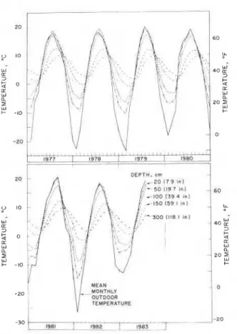
For reference purposes, the average monthly air temperature and soil temperature at various depths for the years 1977 to 1983
[lo]
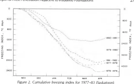
are presented in Figure 1. The freezing index for Saskatoon for the same years is given in Figure 2.DISCUSSION
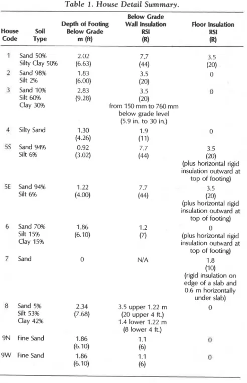
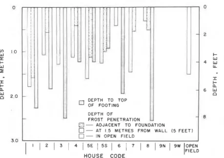
Table 1 summarizes the basic insulation configurations for the houses. The annual maximum depth of frost penetration at each location for the nine houses is summarized in Figures 3 to 6. Since the maximum depth of frost penetration varies with distance from the foundation, values are given at a distance of 1.5 m (5 ft.) from the foundation and ad- jacent to the wall. Due to transient heat transfer effects, these max- imums do not always occur simultaneously. The depth to the top of the
So 1197 on1 . , I I MEAN MONTHLY OUTDOOR
I
TLMPERATURE -301-..
/-20 1982 [ 1 9 ~ 31-
-Depth of Frost Penetration Adjacent to Insulated Foundations 271
I
l
l
NOV DEC JAN FEB MAR APR
Figure 2. Cumulative freezing index for 1977-83 (Saskatoon).
footing below grade is shown. Open field frost penetration with naturally occurring snow cover
[lo]
is also plotted. In some cases, frost penetra- tion depths lower than the open field data were recorded. Variations in snow cover and soil conditions could cause these local differences.Figures 3 to 6 clearly indicate that increasing the thermal resistance of the floorlwall system below grade will increase the depth of frost penetration. In practical terms, however, only extremely well insulated foundations such as houses 1 and 5 have frost penetration levels near
the footing depth.
Considering house 55, the zero degree isotherm adjacent to the foun- dation went just below the top of the footing, even during a relatively mild winter, 1980-81 (FI = 1249 O C days) (FI = 2248OF days) yet did not
go below the bottom of the footing even during a severe winter, 1978-79 (FI = 2409
OC
days) (FI = 4336 "F days). This illustrates the effec- tiveness of horizontal insulation in preventing frost from reaching the footingsIn the prairies, the majority of existing basements are cast-in-place con- crete
with
top of footing depths ranging from approximately 1 m (3.3 ft.) (bi-levelor
split level) to 3 m (10 ft.) (bungalow) below finished grade. Mouses 2, 3, 6, 8, and 9 have "deep" foundations (top of footing depth 31.8 rn (6ft.))
with
moderate levels of insulation. All of thedata
for these houses indicate that much higher levels of basement wall insula- tion could be used without causing potentially serious frost penetration. It is probable that the heat loss from the uninsulated concrete floor slab alone would be sufficient to prevent frost penetration to the footingTable 1. House Detail Summary.
Below Crade
Depth of Footing Wall Insulation Floor Insulation House Soil Below Grade RSI RSI
Code Type (fi) (R) (R)
1 Sand 50% 2.02 7.7 3.5 Silty Clay 50% (6.63) (44) (20) 2 Sand 98% 1.83 3.5 0 Silt 2% (6.0'3 (20) 3 Sand 10% 2.83 3.5 0 Silt 60% (9.28) Clay 30% from 150 rnrn to 760 rnrn (20) below grade level
(5.9 in. to 30 in.)
4 Silty Sand 1.30 1.9 0
(4.26) (11)
55 Sand 94% 0.92 7.7 3.5
Silt 6% (3.02) (44) (20)
(plus horizontal rigid insulation outward at
top of footing)
SE Sand 94% 1.22 7.7 3.5
Silt 6% (4.0) (44) (20)
(plus horizontal rigid insulation outward at
top of footing)
6 Sand 70% 1.86 1.2 0
Silt 15% (6.10) (7) (plus horizontal rigid
Clay 15% insulation outward at
top of footing)
7 Sand 0 N/ A 1.8
(10) (rigid insulation on edge of a slab and 0.6 rn horizontally under slab) 8 Sand 5% 2.34 3.5 upper 1.22 rn 0 Silt 53% (7.68) (20 upper 4 ft.) Clay 42% 1.4 lower 1.22 m (8 lower 4 ft.) 9N Fine Sand 1.86 1 .I 0 (6.10) (6) 9W Fine Sand 1.86 1.1 0 (6.10) (6) 272
0 0
i
- - 2;
1.0-
l- a w I- - 4 W W LL 5-
I I I- I- a a - 6 w:
2.0-
n DEPTH TO TOP OF FOOTING-
L
DEPTH OF FROST PENETRATION-
B - ADJACENT TO FOUNDATION0- AT 1 5 METRES FROM WALL ( 5 FEET) - IN OPEN FIELD
3 0
I
1 1 2 1 3 1 4 1 5 E I 5 S I 6 7 8
HOUSE CODE
Figure 3. Depth of frost penetration for 1978-79. FI = 240g°C days (FI = 4336OF days)
r ' U 0 - - I- W - 4 W I A
-
I I-- -
a - 6 W - d a DEPTH TO TOP OF FOOTING1
DEPTH OF FROST PENETRATION1
n - ADJACENT TO FOUNDATION-
0- AT 1.5 METRES FROM WALL ( 5 FEET)
a-
IN OPEN FIELDI
I 1 2 1 3 1 4 1 5 E 1 5 S 1 6 7 1 8 9 N 1 9 W HOUSE CODE0 0 2 fJl I 0 W I-
=
W I- 4 W W LL I I I I- a F a 6 W2
2 . 0 n DEPTH OF FROST PENETRATION 8 3 . 0I
1 1 2 1 3 I 4 / 5 E 5 S l 6 7 8 1 9 N 9 W O P E N 1FlEi-D HOUSE CODEI Figure 5. Depth of frost penetration for 1980-81. FI = 124g°C days (FI = 2248OF days).
0 0 2 fJl 1 0 W I- K W F 4 W W LL 5 I I I- I- a a 6 W W 0 2 . 0 DEPTH TO TOP n OF FOOTING DEPTH OF FROST PENETRATION 6 - ADJACENT TO FOUNDATION
- AT 1.5 METRES FROM WALL ( 5 FEET)
- IN OPEN FIELD 3.0
I
I 1 2 3 1 4 1 5 E I 5 S 1 6 1 7 1 8 1 9 ~ 1 9 W HOUSE CODE
Depth of Frost Penetration Adjacent to Insulated Foundations 275
depth. In house 8, the lower wall insulation was reduced to RSI 1.4 (R 8) to allow additional heat loss because the owner (a structural engineer) was concerned about frost heaving of the footings. For this house, Figure 3 shows that during a cold winter (FI = 2409°C days) (Fl = 4336°F days) the frost penetration adjacent to the wall was less than 1 m (3.3 ft.).
In "shallow basement" constructions (top of footing depth 61.8 m (6 ft.)), very high levels of wall and floor insulation can result in potentially harmful frost penetration, as in the case of house 5. In the majority of cases where a cast-in-place, uninsulated concrete floor slab is used, the floor slab provides a substantial heat source; the amount of wall insula- tion that can be safely used will be related to the backfill depth. In house 4, a wall insulation level of RSI 1.9 (R 11) resulted in a frost penetration of 0.8 m (2.6 ft.) in a moderate winter (FI = 1757°C days) (FI = 3163°F days), with very light (0 to 50 mm) (0 to 2 in.) snow cover, so it is possible that the frost could reach footing depth during a severe winter.
House 7 is a slab on grade construction with perimeter in-slab forced air heating. This is not a common house foundation but a large number of commercial/light industrial and farm livestock buildings use founda- tions of this type. Although temperatures under the slab are not reported, it is expected that freezing isotherms would extend well under the foundation. For this location, a low water table and sandy soil prevented any foundation heaving, but this insulation system is not recommended.
The depth of frost penetration is strongly dependent upon the thermal conductivity and the volumetric heat capacity of the soil, that depend on many variables, primarily water content. Although an infinite number of possible combinations exist, Goodrich [ I l l has shown that in general, sands and gravels experience deeper frost penetrations than fine grained soils.
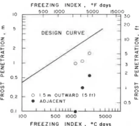
When analyzing frost penetration data, designers and researchers often refer to the Design Curve [9,12,13] which relates the maximum depth of frost penetration to the freezing index. This curve was originally developed from observed frost penetration under snow cleared airport runways in the northern United States and is based on a granular soil type and a limited range of FI. Although useful for estimations under similar conditions, it has been shown to be less reliable for other ap- plications [14].
For estimating frost penetration near basements, it is proposed that the design curve be modified to account for heat input. As the thermal resistance of the insulation increases, the influence of the basement on
D. A. FICLEY AND L. ). SNODCRASS
FREEZING INDEX
.
O F daysI0 t 5 0 0 1000 r l l l5000 l 115000 1 3 0 DESIGN CURVE LT L I I- W L L L, 0
1
0 I 5 m OUTWARD :5 f f ' ADJACENT 0 5 0 1 h e k 100 5 0 0 1000 5000 FREEZING INDEX.
O C d a y sFigure 7. Frost penetration vs. freezing index-House 3.
the soil temperature profile decreases and the profile will converge toward open field conditions.
Since different foundation geometries and insulation configurations will affect the overall soil heat input, a separate "modified design curvef' would be required for each case. These foundations represent a large portion of prairie residential designs, therefore these data should apply to many of them.
An example of a modified curve is shown in Figure 7. For house 3, the maximum frost penetration depth adjacent to the foundation and at a distance of 1.5 m (5 ft.) from the foundation are plotted for the three years data were available. Although the range of FI is limited, a relation- ship appears to exist. Since this site was kept snow cleared, the data are more consistent than some of the other sites where snow cover was allowed to accumulate naturally.
FREEZING I N D E X . OF d a y s 500 1000 5000 15000 0 30
F
0 1 5 m OUTWARD ADJACENT 0 1-
100 500 1000 5000 FREEZING INDEX , OC d a y sDepth of Frost Penetration Adjacent to Insulated Foundations 277 Another example of a modified curve is shown in Figure 8. The data for maximum frost penetration at a distance of 1.5 m (5 ft.) from the foundation follows a relationship similar to the design curve but is ver- tically offset to account for heat supplied by the basement. The observa- tions adjacent to the basement wall are almost independent of FI, show- ing the effectiveness of the horizontal insulation skirt in preventing frost penetration. At lower FI values where the frost penetration does not reach the footing, the values begin to decrease.
Further measurements of these soil temperature profiles are being made under snow cleared conditions over a sufficient period of time (range of FI) to develop modified design curves.
CONCLUSIONS
Although these data were collected from a limited number of sites, a number of generalizations can be made. Additional data are needed to support these observations.
1. Observations around house 1 with a deep foundation show that even with RSI 7.7 (R 44) wall and RSI 3.5 (R 20) floor insulation, frost did not penetrate to the depth of footing during a cold winter (FI = 2073°C days) (FI = 3731 O F days) with minimal (75 mm) (3 in.) snow cover.
2. Observations around house 5s with a heavily insulated shallow foun- dation, RSI 7.7 (R 44) wall and RSI 3.5 (R 20) floor, shows that frost can penetrate to the footing level even during a mild winter (FI = 1249OC days) (FI = 2248°F days) with no snow cover. The additional 0.3 m (1
ft.) of backfill, 1.22 m (4 ft.) above footing on the east side, seems to be the minimum necessary to prevent frost penetration to the footing. The horizontal insulation thickness and width should be in- creased on new constructions of this type.
3. New and existing basements with uninsulated concrete floor slabs can safely use much higher levels of wall insulation than was pre- viously assumed.
-For deep basements, the thickness of wall insulation may become an economic decision since frost penetration to the footings is very unlikely.
-For shallow basements, consideration should be given to the maxi- mum insulation level, although the economic optimum (2 RSI 2 to
4) (R 11 to 22) can normally be used. For new constructions, peri- meter insulation over the footings will allow the safe use of higher levels of wall insulation.
4. To prevent the soil under a surface slab from freezing, vertical insula- tion on the outside edge of the slab extending downward is required.
278 D. A. FIGLEY AND L. J. SNODGRASS
Determination of the thickness, and more importantly, the depth of the insulation is beyond the scope of this study.
ACKNOWLEDGEMENT
This paper is a contribution from the Division of Building Research, Na- tional Research Council of Canada and is published with the approval of the Director of the Division.
REFERENCES
1. Preserved Wood Foundations, Canadian Wood Council, CWC Datafile WB-4 (1983).
2. Penner, E. and Burn, K. N., "Adfreezing and Frost Heaving of Foundations," Canadian Building Digest, 128, Division of Building Research, National Research Council of Canada (1970).
3. Crocker, C. R., "Moisture and Thermal Considerations in Basement Walls," Canadian Building Digest, 161, Division of Building Research, National Research Council of Canada (1974).
4. Burn, K. N., "Frost Action and Foundations," Canadian Building Digest, 182, Division of Building Research, National Research Council of Canada (1976). 5. Tao, S. S., Bomberg, M., Hamilton, J. J., Glass Fibre as Insulation and Drainage Layer on Exterior of Basement Walls, ASTM Special Technical Publication 718, American Society for Testing Materials (1980).
6. Goodrich, L. E., An Introductory Review of Numerical Methods for Cround Thermal Regime Calculations, Division of Building Research, National Research Council of Canada, NRCC 20742 (1982).
7. Farouki, O., "Evaluation of Methods for Calculating Soil Thermal Conduc- tivity," CRREL Report 82-8, U.S. Army Cold Regions Research and Engineer- ing Laboratory (1982).
8. Johnston, C. H., Instructions for the Fabrication of Thermocouple Cables for Measuring Cround Temperatures, National Research Council of Canada, NRCC 7561 (1963).
9. Penner, E. and Crawford, C. B., Frost Action and Foundations, Division of Building Research, National Research Council of Canada, NRCC 21089 (1983).
10. Daily Soil Temperature Data 1977-1 983, Atmospheric Environment Ser- vice, Environment Canada, ISSN 0703-6523.
11. Coodrich, L. E., The Influence of Snow Cover on the Cround Thermal Regime, Division of Building Research, National Research Council of Canada, NRCC 20588 (1982).
12. U.S. Corps of Engineers, Addendum No. 1, 1945-47, to report on Frost Penetration, 1944-45, Boston (1949).
13. Brown, W. C., "Difficulties Associated with Predicting Depth of Freeze or Thaw," Canadian Geotechnical lournal, 1 (1964).
Depth of Frost Penetration Adjacenr to Insulated Foundations 279
14. Crawford, C. B., Frost Penetration Studies in Canada as an Aid to Construc- tion, Division of Building Research, National Research Council of Canada, NRCC 3573 (1955).
THE AUTHORS
Don Figley is an Assistant Research Officer with the Division of Build- ing Research, National Research Council of Canada, Saskatoon, Sask. He has been involved in research in low energy housing and energy conser- vation and has co-authored a number of papers dealing with air infiltra- tion in housing and low temperature air cooled solar collectors. He is a graduate of the University of Saskatchewan with an M.Sc. in mechanical engineering and is a registered professional engineer in Saskatchewan. Larry Snodgrass is a Senior Technical Officer with the Division of Building Research, National Research Council of Canada, Saskatoon, Sask. He has been involved it7 research in the geotechnical field, prin- cipally related to performance of shallow foundations on prairie clay soils, and has co-authored a number of papers related to instrumenta- tion in this field. More recently his emphasis has been focussed on the effects of frost penetration in soils adjacent to insulated foundations. He is a graduate (C.E.T.) Civil Engineering Technologist.
APPENDIX A HOUSE CODE 1-9
USC UNIT CONVERSIONS FOR APPENDIX A Thermal Resistance
RSI 1 (mZOC/W) = R 5.678 (hr ft20FIBTU) RSI 2.1 = R 12 RSI 3.5 = R 20 RSI 4.9 = R 28 RSI 7.0 = R 40 RSI 7.7 = R 44 Density
Length 1 meter (m) = 3.28 ft. = 39.37 in. 12 mm = 112 in. 15.9 mm = 518 in. 19 mm = 314 in. 25.4 mm = 1 in. 38 mm = 1 112 in. 100 mm = 4 in. 150 mm = 6 in. 203 mm = 8 in. 228 mm = 9 in. 305 mm = 12 in. 406 mm = 16 in. 610 mm = 24 in.
D. A. FICLEY AND L. ). SNODCRASS
150 pm = 6 mil = 0.006 in.
Framing Lumber
House 1
This structure, built in 1980, is a continuously heated wood framed double stud wall house on a full height (2.44 m) double stud preserved wood foundation and crawl space (Figure a).
To support
the
soil pressure,the
basement wall system incorporates38
x
140 mm studs, 406 mm O.C. with 15.9 mm plywood sheathing onthe exterior. The backfill is 1 -42
rn
above the top of the basement floor.The inner vertical load bearing wall uses 38 x 89 mm studs, 406 mm
O.C. for an overall wall thickness of 330 mm. Both walls bear on a wood
footing set on 150 mm of crushed rock.
The stud spaces and cavity are filled with glass fibre batt insulation (14.5 kglm3) with an overall thermal resistance of RSI 7.7. The inside of
the wall above the floor is sheeted with 12 mm drywall.
The basement floor is 38
x
235 mm joists topped with 15.9 mm plywood bearing on the inner load bearing wall. The cavity betweenthe
floor joists is insulated to RS1 3.5 using glass fibre batts.
The crawl space (0.84 m from the underside of floor joists to top of grade) is not heated or ventilated. 150 prn polyethylene sheeting was
Depth of Frost Penetration Adjacent to insulated Foundations 281 placed on the ground surface to reduce moisture transmission from the soil.
Soil from the original excavation was used to backfill the basement. The general soil type is 50 percent silty clay and 50 percent sand.
An electric forced air furnace is used to heat the house.
Monthly temperature measurements were taken from January 1981 to April 1983. Seventeen thermocouples were used to measure soil tem- peratures at various locations on the north side of the house.
OPEN FIELD
"1
4 NORTH 0 2 4 6 8 I O m PLAN V I E W282 D. A. FIGLEY AND L. J. SNODGRASS House 2
This structure, built in 1955, is a continuously heated wood frame house on a full height (2.36 m) cast in place 228 mm thick concrete basement with 0.64 m above grade (Figure
b).
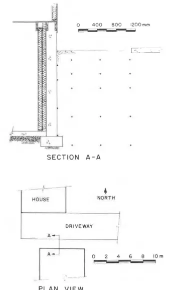
The floor slab is 100 mm thick uninsulated concrete cast over a 100 mm gravel pad placed on undisturbed soil. The top surface of the slab is bare concrete. SECTION A-A - - --
4
HOUSE NORTH I I I DRIVEWAY I PLAN VIEWDepth of Frost Penetration Adjacent to Insulated Foundations 283 During the fall of 1979, the interior of the wall from the subfloor to the underside of the floor joists was framed with 38 x 89 mm studs 610 mm
o.c, set out 75 mm from the concrete. The back space was insulated
with RSI 1.4 glass fibre batts and the space between rhe studs was fijled with RSI 2.1 glass fibre batts yielding a total wall thermal resistance of RSI 3.5. The glass fibre
batt
insulation density was 14.5 kglm3. The entire in- side wall was sheeted with 12mrn
drywall.The basement excavation was backfilled with soil from the site. The
general soil type is 2 percent silt and 98 percent sand.
The heating system is natural gas fired forced air furnace with automatic fan operation.
Monthly temperature measurements were taken from December 1979 to March 1983. Nineteen thermocouples were used to measure ground temperatures on the north side of the house.
H o u s e 3
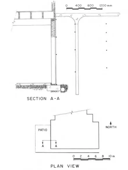
This structure, built in 1976, is a continuously heated wood frame house on a full height (2.32 m) preserved wood basement (Figure c).
The top of the basement wall extends 100 mm above the top of the 100 mm thick concrete patio slab. The basement wall system used 38 x
140 mm studs, 305 mm O.C. with 15.9 mm plywood sheathing on the
exterior. The walls bear on uninsulated concrete footings cast on un- disturbed soil. The basement floor is a 100 mm thick concrete slab cast over 150 mm of gravel on undisturbed soil. The top surface of the slab is bare concrete.
The cavities between the studs are filled with 14.5 kg/m3 glass fibre batt insulation RSI 3.5 for 0.60 m down from the top plate. The lower portion of the wall is uninsulated. The inside of the stud wall is sheeted with 12 mm drywall.
Soil from the original excavation was used to backfill the basement. The general soil type is 30 percent clay, 60 percent silt, and 10 percent sand.
A natural gas fired forced air furnace is used to heat the house. Soil temperature measurements were taken monthly from September 1976 to April 1981. Thirteen thermocouples were used to measure soil temperatures at various locations on the west side of the house under the concrete patio slab.
H o u s e 4
This structure, built in 1979, is a continuously heated wood frame house on a full height (2.44 m) corrugated steel panel basement with
284 D. A. FICLEY AND L. J. SNODGRASS
1.22 rn above grade (Figure d). The wall panels are 16 ga. galvanized steel with 76 mrn deep corrugations and rest on 3 mm
x
203 mm steel plate footings on a 200 rnm gravel pad.The floor slab is 75 mm thick uninsulated concrete cast over a 200 mm gravel pad placed on undisturbed soil. The top surface of the slab is bare concrete.
The exterior of the wall from the underside of the floor joists to the
4
NORTH
P L A N V I E W
Depth of Frost Penetration Adjacent to Insulated Foundations 285
top of the footing is insulated with 68 mm thick asphalt coated rigid glass fibre insulation with a density of 144 kglm3 having a nominal (dry) thermal resistance of RSI 2.0. The exterior of the insulation above grade was covered with metal lath and parged.
The basement excavation was backfilled with soil from the original ex- cavation. The general soil type is silty sand to a depth of 1.52 m and soft clay below that level.
SECTION A - A OPEN G R A S S E D A R E A A 7
4
NORTH P L A N VIEW286 D. A. FICLEY AND L. J. SNODCRASS
The heating system is a natural gas fired forced air furnace with automatic fan operation.
Monthly temperature measurements were taken from October 1979 to April 1981. Twenty-five thermocouples were used to measure ground temperatures on the north side of the house.
House 5
This structure, built in 1978, is a continuously heated wood framed double stud wall house on a full height (2.44 m) double stud preserved wood foundation (south side Figure e.1 and east side Figure e.2).
To support the soil pressure, the basement wall system uses 38 x 89 mm studs, 406 mm O.C. with 19 mm plywood sheathing on the exterior.
The inner wall uses 38 x 89 mm studs, 406 mm O.C. for an overall wall
thickness of 305 mm.
The stud spaces and cavity are filled with glass fibre batt insulation with an overall thermal resistance of RSI 7.7. The inside of the wall is sheeted with 12 mm drywall.
The basement floor is 38 x 140 mm joists topped with 15.9 mm plywood. The main wall and the floor joists are supported by a 200 x
600 mm concrete footing placed on undisturbed soil. The spaces be- tween the floor joists are insulated with glass fibre batt insulation to RSI 3.5. All of the glass fibre batt insulation had a density of 14.5 kglm3.
The crawl space (0.28 m from the underside of floor joists to top of grade) is not heated or ventilated. 150 pm polyethylene sheeting was placed on the soil surface to reduce moisture transmission from the soil. The concrete footings were cast on undisturbed soil and are insulated with two 38 mm layers of SM (STYROFOAMTM RSI 1.3 per layer) extend- ing horizontally from the top of the footing. The lower layer extends outward 0.92 m and the upper layer 0.61 m.
Soil from the original excavation was used to backfill the basement. The south side backfill height is 0.92 m above the top of the footing and the east side backfill height is 1.22 m above the top of the footing. The general soil type is 6 percent silt and 94 percent sand.
The house is heated with an electric forced air furnace.
Monthly temperature measurements were taken from October 1978 to April 1983. One string of 23 thermocouples was installed on the east side of the house. The second string of 20 thermocouples was installed on the south side of the house.
House 6
This structure, built in 1976, is a continuously heated wood frame house on a full height (2.36 m) cast in place 203 mm thick concrete
Depth of Frost Penetration Adjacent to Insulated Foundations 287 basement with 0.6 m above grade (Figure f). The floor slab is 100 mm thick uninsulated concrete cast over a 100 mm thick gravel pad placed on undisturbed soil. The top surface of the slab is bare concrete.
The exterior perimeter of the foundation wall from the underside of the subfloor to the top of the footing is insulated with 38 mm of 144 kglm3 rigid glass fibre insulation having a nominal thermal resistance of RSI 1.2. An additional 1.22 m high layer of 12 mm rigid glass fibre insula- tion (SOUNDSTOPTM) was installed from 60 mm below the subfloor
SECTION A - A
.
4
NORTH GRASSEDLA
A R E A P L A N VIEW288 D. A. FIGLEY AND L. j. SNODGMS
downwards. The exterior of the SOUNDSTOP was covered with ex-
panded metal lath and parged to provide mechanical protection. Thirty- eight mm thick 133 kglm3 rigid glass fibre insulation, extending horizon-
tally outward 0.30 m, was installed over the concrete footing.
The basement excavation was backfilled with soil from the site. The general soil type is 15 percent clay, 15 percent silt, and 70 percent sand. The heating system is a natural gas fired forced air furnace with automatic fan operation.
SECTION B - B
4
NORTH 3 h G R A V E L D R I V E W A YPLAN
VIEWDepth of Frost Penetration Adjacent to Insulated Foundations 289
Temperature measurements were taken monthly from January 1977 to April 1981. Nineteen thermocouples were used to measure soil tem- peratures at various locations on the west side of the house.
House
7
This structure, built in 1980, is a continuously heated wood framed single story garagelworkshop with a slab on grade foundation (Figure g).
I*: #I+
SECTION A - A4
NORTH GRASSED A A-1
O 2 4 6 8 I O m P PLAN VIEW290 D. A. FIGLEY AND L. J. SNODGRASS
The concrete slab is nominally 100 mm thick with the 0.50 m perimeter strip thickened to 305 mm for structural support and to ac- commodate in-slab services. The slab was cast on a 200 mm gravel pad on undisturbed soil. The top surface of the slab is bare concrete.
Fifty mm (STYROFOAMTM RSI 1.75) was installed on the vertical edge of the slab and under the slab extending from the perimeter inward for 0.61 m.
The soil type is 100 percent sand from the underside of the slab to 2.0 m below grade. No soil testing was done below that depth.
.
.
SECTION A - A.
NORTH1
Y
DRIVEWAY..-
P L A N VIEWDepth of Frost Penetration Adlacent to Insulated Foundations 291
The heating system is a natural gas fired forced air furnace with the warm air supplied to a perimeter in-slab duct system. The furnace fan is operated continuously and the circulating air temperature varies from approx. 60°C with the furnace firing t o 20°C (normal room temperature) during fan only operation.
Temperature measurements were taken monthly from October 1980 to March 1983. Twenty-three thermocouples were installed at various locations in the floor slab and soil adjacent to the concrete driveway.
S E C T I O N A - A
GRASSED AND T R E E D & R E A
4
NORTH
0 2 4 6 8 I O m
P L A N VIEW
292 D. A. FICLEY AND L. J. SNODCRASS
House 8
This structure, built in 1977, is a continuously heated wood frame
house on a full depth (2.44 m) preserved wood basement (Figure h).
The top of the basement wall extends 200 mm above grade level. The
basement wall system uses 38 x 184 mm studs, 406 rnm O.C. with 15.9
m m
plywood
sheathing on the exterior. The walls bear on uninsulated concrete footings cast on 50 mm granular fill. The basement floor is aSECTION A - A HOUSE 4 NORTH GRAVEL COVER O 2 4 6 8 I O m P L A N V I E W
Depth of Frost Penetration Adjacent to Insulated Foundations 293
100 mm thick concrete slab cast over 200 mm of gravel on undisturbed soil. The top surface of the slab is bare concrete.
Glass fibre batt insulation (14.5 kglm3) was installed in the stud spaces, the upper 1.22 m of the wall has RSI 3.5 batts and the lower 1.22 m por- tion has RSI 1.4 batts. The interior of the wall is sheeted with 12 mm drywall.
Soil from the original excavation was used to backfill the basement.
SECTION B - B CONC. PATIO GRAVEL COVE.
rB
4 NORTH 0 2 4 6 8 IOm P L A N VIEW294 D. A. FIGLEY AND L. ). SNODGRASS
The general soil type is 42 percent clay, 53 percent silt, and 5 percent sand.
The space heating is provided by a forced air electric furnace.
Temperature measurements were taken monthly from August 1977 to April 1981. Twenty-one thermocouples were used to measure soil tem- peratures at various locations on the north side of the building.
House 9
This structure, built in 1976, is a continuously heated wood frame house on a full height (2.29 m) cast in place 203 mm thick contrete base- ment with 0.53 m above grade (west wall Figure i.1 and north wall Figure i.2).
The floor slab is 100 mm thick uninsulated concrete cast over a 100 mm gravel pad placed on undisturbed soil. The top surface of the slab is bare concrete.
The exterior perimeter of the north foundation wall from the under- side of the subfloor downwards 0.37 m is insulated with 38 mm of 112 kg/m3 rigid glass fibre insulation. A 38 x 38 mm nailer strip was placed below the insulation and the remainder of the wall from below the nailer strip to the top of the footing was insulated with 38 mm of 144 kg/m3 rigid glass fibre insulation.
The west wall insulation configuration is the same as the north wall; however, the rigid glass fibre insulation has a density of 48 kg/m3. Rigid glass fibre insulation, extending horizontally outward 0.30 m, was in- stalled over the top of the concrete footings.
Soil from the original excavation was used to backfill the basement. The general soil type is fine sand.
A natural gas fired forced air furnace with automatic fan operation is used to heat the house.
Monthly temperature measurements were taken from November 1976 to January 1980. Fifteen thermocouples on the north wall and 13 thermocouples on the west wall were used to measure soil tempera- tures at various locations.
T h i s p a p e r , w h i l e b e i n g d i s t r i b u t e d i n r e p r i n t f o r m by t h e D i v i s i o n o f B u i l d i n g R e s e a r c h , r e m a i n s t h e c o p y r i g h t o f t h e o r i g i n a l p u b l i s h e r . I t s h o u l d n o t b e r e p r o d u c e d i n whole o r i n p a r t w i t h o u t t h e p e r m i s s i o n of t h e p u b l i s h e r . A l i s t o f a l l p u b l i c a t i o n s a v a i l a b l e f r o m t h e D i v i s i o n may b e o b t a i n e d by w r i t i n g t o t h e P u b l i c a t i o n s S e c t i o n . D i v i s i o n o f B u i l d i n g R e s e a r c h , N a t i o n a l R e s e a r c h C o u n c i l o f C a n a d a , O t t a w a , O n t a r i o , K1A 0R6.