HAL Id: hal-02011634
https://hal.univ-lorraine.fr/hal-02011634
Submitted on 8 Feb 2019
HAL is a multi-disciplinary open access
archive for the deposit and dissemination of
sci-entific research documents, whether they are
pub-lished or not. The documents may come from
teaching and research institutions in France or
abroad, or from public or private research centers.
L’archive ouverte pluridisciplinaire HAL, est
destinée au dépôt et à la diffusion de documents
scientifiques de niveau recherche, publiés ou non,
émanant des établissements d’enseignement et de
recherche français ou étrangers, des laboratoires
publics ou privés.
Frequency dependence of the longitudinal spin Seebeck
effect
Yong Xu, Weisheng Zhao, Stéphane Mangin
To cite this version:
Yong Xu, Weisheng Zhao, Stéphane Mangin. Frequency dependence of the longitudinal spin Seebeck
effect. Physical Review B: Condensed Matter and Materials Physics (1998-2015), American Physical
Society, 2018, 98 (14), pp.144408. �10.1103/physrevb.98.144408�. �hal-02011634�
Frequency dependence of the longitudinal spin Seebeck effect
Yong Xu,1,2Weisheng Zhao,1,*and Stéphane Mangin2,†
1Fert Beijing Institute, BDBC, School of Microelectronics, Beihang University, Beijing, 100191, China 2Institut Jean Lamour, CNRS UMR 7198, Université de Lorraine, Nancy F-54500, France
(Received 12 August 2018; revised manuscript received 13 September 2018; published 8 October 2018) The spin Seebeck effect provides an easy way to create and manipulate spin current. Schreier et al. experimentally observed a decrease of spin Seebeck voltage at high frequencies in the yttrium iron garnet/Pt system [Phys. Rev. B 93,224430(2016)]. The frequency dependence was attributed to the magnon spectrum. Here we provide a different explanation using the frequency dependence of the ac spin current. By combining a phenomenological two-temperature model with the ac- temperature method, our calculation shows that the frequency dependence of the spin current is determined by the thermal wavelength and the thermal boundary conditions of the phonons and the magnons.
DOI:10.1103/PhysRevB.98.144408
I. INTRODUCTION
Since its discovery, the spin Seebeck effect (SSE) has drawn a lot of attention for its potential in energy harvesting and information technology [1–7]. Xiao et al. predicted that the spin current generated by SSE is proportional to the differ-ence between the magnon temperature in the ferromagnet and the electron temperature in the normal metal [8]. In magnetic insulators, the magnon temperature differs from the phonon temperature due to the difference in thermal boundary con-ditions [9]. Schreier et al. analyzed the electron, phonon, and magnon temperature profiles and compared with experimental results under static temperature gradients [10].
Measurements based on ac-temperature gradients have shown to have better precision [11]. Recently efforts have been made to push the application of the SSE to high frequen-cies. Agrawal et al. studied the longitudinal SSE (LSSE) on yttrium iron garnet/Pt (YIG/Pt) with a microsecond temporal resolution [12]. Schreier et al. reported experimentally the frequency dependence of the LSSE up to microwave frequen-cies [13]. Kimling et al. demonstrated the LSSE at several picoseconds through the pump-probe method with an ultrafast heat-transfer process [7]. From those measurements, a strong link has been established between the SSE and the underlying heat propagation. Therefore it is likely that for the SSE at high frequencies the underlying temperature oscillation plays a vital role.
In our previous work [14], we provided a framework to analyze the frequency dependence of the temperature oscil-lation in the Hall cross geometry from 1 Hz to 1 kHz. It has been shown that the frequency dependence of thermomagnetic signals can be interpreted using the thermal wavelength of the oscillating heat current.
Our ac-temperature model [14] considered the heat propa-gation only in the phonon system, wherein microsecond time
*[email protected] †[email protected]
scale the phonons, the electrons, and the magnons are fully thermalized. In this paper in order to extend the ac model to higher frequencies, we consider the heat conduction in both the electron channel and the magnon channel [15] of YIG. The two heat channels are coupled through the phonon-magnon coupling. In the metal layer, the electrons and the phonons are fully thermalized due to strong electron-phonon interaction at the nanosecond timescale, which corresponds to the frequency range of interest.
The details of the model are explained in Sec.II. In Sec.III, the temperature profiles of the magnons and the phonons are presented. The frequency dependences of the SSE with different boundary conditions are discussed in Sec.IV.
II. MODEL
The typical sample structure in Ref. [13] is GGG (500 µm)/YIG (x nm)/Pt (10 nm), where x = 50, 270, 2800, 6700, and 30 000. As the thickness of Pt is much thinner than that of the other two layers, we neglect the Pt layer from the heat-transport point of view. In our model, the system includes a GGG substrate of 500 µm and a YIG layer of x nm, where x = 50, 270, and 2800. (Fig.1) The remaining two samples in Ref. [13] x = 6700 and 30 000 are neglected for simplicity. In the YIG layer, the coupled time-dependent heat equations for the phonons and the magnons read
Cp ∂Tp ∂t = Kp ∂2Tp ∂x2 , (1) Cm ∂Tm ∂t = gpm(Tp− Tm) + Km ∂2Tm ∂x2 , (2)
where the Cp and Cmare the volume thermal capacitances,
Tp and Tm the temperatures, Kp and Km the thermal
con-ductivities, and gpmis the phonon-magnon coupling constant.
The subscripts p and m stand for the phonon channel and the magnon channel, respectively.
YONG XU, WEISHENG ZHAO, AND STÉPHANE MANGIN PHYSICAL REVIEW B 98, 144408 (2018)
FIG. 1. The sketch of the samples GGG (500 µm)/YIG (x nm) where x = 50, 270, and 2800. An oscillating heat flux is applied on the surface.
Due to the absorption of laser or microwave, an oscillating heat flux F = F0cos(ωt − π/4) is applied on the YIG surface
[13]. Note that in the experiments the dc part of the heat flux does not contribute to the LSSE and thus can be neglected. For a semi-infinite media, the one-dimensional solution under an oscillating heat flux is analytical: [16]
Tp= F0 √ 2Kpk e−kxsin (ωt − kx), (3) where k =!ω 2α, ω = 2πf , and α = Kp
Cp. Since in our model the thickness of the samples is finite, a numerical analysis has been done to confirm that the analytical solution is close to the numerical solution (data not shown). Equation (2) is used for the following calculation of the magnon temperature with the phonon temperature given by Eq. (3). The parameters used in the calculation are listed in TableI.
III. MAGNON TEMPERATURE AND PHONON TEMPERATURE
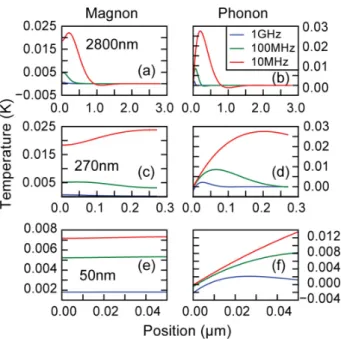
The right column of Fig.2shows the temperature profiles of the phonons for the three samples at 10 MHz, 100 MHz, and 1 GHz. According to Eq. (3), the oscillation ampli-tude of the phonon temperature decreases exponentially with the position. One can define the thermal wavelength of the phonon as λp= 2πk = 2
"
π Kp
f Cp. It is also referred to as the thermal penetration depth [18] because at the position x = λp
the oscillation amplitude of the phonon temperature decays to almost zero. At 10 MHz, 100 MHz, and 1 GHz, the deduced thermal wavelengths of the phonons are 1.6 µm [Fig.2(b)], 0.51 µm [Fig.2(d)], and 0.16 µm [Fig. 2(f)], respectively.
The left column of Fig.2shows the temperature profiles of the magnons calculated numerically using Eq. (2) for the three samples at 10 MHz, 100 MHz, and 1 GHz. The temperature
TABLE I. Parameters used in the calculation. C and K corre-spond to the thermal capacitance and thermal conductivity, respec-tively. The subscripts p and m stand for phonons and magnons, respectively. Gpp is the interfacial phonon-to-phonon thermal
conductance. Cp(YIG) 2.9 × 10⁶J/(Km3) [7] Kp(YIG) 6.0 W/(mK) [10] Cm(YIG) 1200 J/(Km3) [17] Km(YIG) 4.85 W/(mK) [17] Cp(GGG) 2.0 × 10⁶J/(Km3) [7] Kp(GGG) 8.0 W/(mK) [10] Gpp(YIG/GGG) 2.04 × 10⁸W/(m2K) [10] Gpp(YIG/Pt) 2.79 × 10⁸W/(m2K) [10]
FIG. 2. The magnon temperature (left column) and the phonon temperature (right column) as a function of the position for the sample with YIG thickness of 2800 nm (a), (b), 270 nm (c), (d), and 50 nm (e), (f). Both the magnon temperature and the phonon temperature are oscillating at all the positions. The temperature profiles are shown for t = π/ω.
oscillation of the magnons is driven by the phonon system through the phonon-magnon coupling Gpm. The Cm/Gpm =
4 ps corresponds to the timescale for the thermalization be-tween the phonons and the magnons, which implies that phase delay between the oscillation of the magnon temperature and the phonon temperature does not exist in the frequency range up to GHz.
We find that the following two features are essential for the temperature profiles for the ac case:
(1) The thermal boundary conditions of the magnons, which is the same as the dc method. Since the magnons in YIG are thermally insulated from the other layers [9,10], the temperature gradient of the magnon temperature is zero at the boundaries. [See Figs.2(a),2(c), and2(e)].
(2) The thermal wavelength of the magnons, which is unique to the ac method. Following the definition of the thermal wavelength of the phonons, the thermal wavelength of the magnons is given by the equation λm= 2πk = 2
"
π Km
f Cm. Note λm is different from the magnon wavelength of the
magnon theory. At 10 MHz, 100 MHz, and 1 GHz, the thermal wavelengths of the magnon are 71.3, 22.5, and 7.13 µm, respectively. Due to the differences in thermal properties, the magnon temperature [see Fig. 2(c)] tends to be more homogenous than the phonon temperature.
For example, Fig. 2(e) shows the magnon temperature profiles at 10 MHz, 100 MHz, and 1 GHz for the sample of 50-nm YIG. As the YIG thickness is much smaller than the thermal wavelength of the magnons, we observe a uniform magnon temperature in the YIG. It results from both a large λmand the thermal boundary conditions of the magnons.
IV. SPIN SEEBECK EFFECT
The theory of LSSE predicts that the spin current induced by the temperature gradient is proportional to Te− Tmat the
interface. Assuming the electrons of Pt and the phonons of YIG at the interface of YIG/Pt are in thermal equilibrium, Te− Tmcan be taken as the temperature difference between
the phonons and the magnons in YIG (Tp− Tm). From the
calculation of the phonon temperature oscillation and magnon temperature oscillation, we extract the oscillation amplitude of the temperature difference between the phonons and the magnons.
A. Frequency dependence of LSSE
Figure3presents the temperature difference between the phonons and the magnons as a function of the position. Based on the comparison between the YIG thickness and the two parameters λm and λp, the temperature profiles can be
generally divided into the following two regimes:
λp≪ YIG thickness: For the sample of 2800 nm YIG
[Fig.3(a)] with the frequency above 10 MHz (λp(10 MHz) =
1.61 µm), we observe a monotonous decay of the ampli-tude as a function of thickness. In this case, the phonon temperature that drives the oscillation of magnon temper-ature decays to almost zero at the interface of GGG/YIG. For a 270-nm-thick YIG, the temperature difference pro-file at 1 GHz (λp(1 GHz) = 161 nm) shows a similar trend
[Fig.3(b)].
λm≫ YIG thickness: For example, in Fig.3(b)the
tem-perature difference does not decay monotonously for the frequencies lower than 100 MHz [λm(100 MHz) = 510 nm].
The temperature difference reaches the minimum in the center of YIG. In this case, the magnon temperature is homogenous whereas the oscillation amplitude of the phonon temperature decreases exponentially as a function of the position [for example, see Figs.2(c)and2(d)]. Note that similar curves can be observed for low frequencies in Fig.3(a)and for all the frequencies in Fig.3(c).
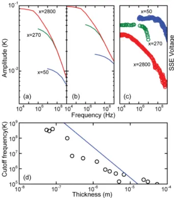
The temperature difference at the interface is extracted from Fig.3 and plotted against the frequency in Fig. 4(a). Note that the calculation reproduces qualitatively the
experi-FIG. 3. The amplitude of the temperature difference between the phonons and the magnons (Tp− Tm) as a function of the position
for the samples with YIG thickness of 2800 nm (a), 270 nm (b), and 50 nm (c).
FIG. 4. Frequency dependence of the temperature difference (Tp− Tm) at the YIG (x nm)/Pt interface considering (a) no
in-terfacial thermal conductance and (b) the inin-terfacial thermal con-ductance, where x = 2800 (red), 270 (green), and 50 (blue). (c) The experimental frequency dependence reported in Ref. [13]. (d) The cutoff frequency as a function of the YIG thickness. The solid line corresponds to the calculation results and the empty circles are extracted from Ref. [13].
mental frequency dependence of LSSE [Fig.4(c)] reported by Schreier et al. [13]. The calculated frequency dependence is different from the experimental data in two aspects. First, one cannot directly compare the amplitude between the samples, as the amplitude is proportional to the heat flux applied to the system. In the calculation, we keep the oscillating heat flux constant for the three samples, which is different from the experiments. Second, compared to the experimental data in Fig.4(c), the calculated spin Seebeck signal decays more rapidly than the experimental data. To reconcile the differ-ence, the interfacial thermal conductance is considered in the following.
B. Interfacial thermal conductance
The interfacial thermal conductance Gpp (Kapitza
resis-tance) across the interface YIG/Pt arises from the interfacial phonon scattering. The value of Gpp= 2.79 × 10⁸W/(m2K)
(calculated in Ref. [10]) is used in the calculation. With the interfacial thermal conductance of YIG/Pt considered, a better agreement of our calculation and the experiment is reached [Fig.4(b)].
The comparison between the frequency dependences with [Fig.4(a)] and without Gpp [Fig.4(b)] shows that the
in-terfacial thermal conductance does not significantly change the behavior at low frequencies but largely modifies the
fre-YONG XU, WEISHENG ZHAO, AND STÉPHANE MANGIN PHYSICAL REVIEW B 98, 144408 (2018)
quency dependence at high frequencies. Due to the short ther-mal wavelength at high frequencies, the heat oscillation be-comes sensitive to the interfacial conditions as the frequencies increases.
For a given YIG thickness dYIG, the cutoff frequency fcutoff
can be estimated using the definition of the thermal wave-length of the phonons: λp= dYIG= 2
" π K p
fcutoffCp. In Fig.4(d) the cutoff frequency is shown as a function of the YIG thick-ness, which agrees well with the experimental data reported in Ref. [13].
V. CONCLUSION
In conclusion, the oscillating temperature profiles of the magnons and the phonons at high frequencies are calculated
numerically for GGG/YIG/Pt using a phenomenal two-temperature model. The frequency dependence of LSSE and the estimated cutoff frequency are consistent with the exper-imental values. We find that the thermal wavelength and the boundary conditions of the phonons and the magnons are key ingredients for explaining the LSSE at high frequencies.
ACKNOWLEDGMENTS
W.Z. gratefully acknowledge the National Natural Science Foundation of China (61627813), the International Collabo-ration Project B16001, and the Beijing Advanced Innovation Center for Big Data and Brain Computing (BDBC). Y.X. is thankful for the support from the China Postdoctoral Science Foundation (2017M620569).
[1] K. Uchida, S. Takahashi, K. Harii, J. Ieda, W. Koshibae, K. Ando, S. Maekawa, and E. Saitoh, Observation of the spin Seebeck effect,Nature (London) 455,778(2008).
[2] G. E.W. Bauer, E. Saitoh, and B. J. van Wees, Spin caloritronics,
Nat. Mater. 11,391(2012).
[3] S. Geprägs et al., Origin of the spin Seebeck effect in compen-sated ferrimagnets,Nat. Commun. 7,10452(2016).
[4] L. J. Cornelissen, J. Liu, R. A. Duine, J. B. Youssef, and B. J. van Wees, Long-distance transport of magnon spin information in a magnetic insulator at room temperature,Nat. Phys. 11,
1022(2015).
[5] L. J. Cornelissen, K. J. H. Peters, G. E. W. Bauer, R. A. Duine, and B. J. van Wees, Magnon spin transport driven by the magnon chemical potential in a magnetic insulator,Phys. Rev. B 94,014412(2016).
[6] S. M. Wu, W. Zhang, A. KC, P. Borisov, J. E. Pearson, J. S. Jiang, D. Lederman, A. Hoffmann, and A. Bhattacharya, Antiferromagnetic Spin Seebeck effect, Phys. Rev. Lett. 116,
097204(2016).
[7] J. Kimling, G.-M. Choi, J. T. Brangham, T. Matalla-Wagner, T. Huebner, T. Kuschel, F. Yang, and D. G. Cahill, Picosecond Spin Seebeck Effect,Phys. Rev. Lett. 118,057201(2017). [8] J. Xiao, G. E. W. Bauer, K. Uchida, E. Saitoh, and S. Maekawa,
Theory of magnon-driven spin Seebeck effect,Phys. Rev. B 81,
214418(2010).
[9] D. J. Sanders and D. Walton, Effect of magnon-phonon thermal relaxation on heat transport by magnons,Phys. Rev. B 15,1489
(1977).
[10] M. Schreier, A. Kamra, M. Weiler, J. Xiao, G. E. W. Bauer, R. Gross, and S. T. B. Goennenwein, Magnon, phonon, and
electron temperature profiles and the spin Seebeck effect in magnetic insulator/normal metal hybrid structures,Phys. Rev. B 88,094410(2013).
[11] D. G. Cahill, Thermal conductivity measurement from 30 to 750 K: the 3ω method,Rev. Sci. Instrum. 61,802(1990). [12] M. Agrawal, V. I. Vasyuchka, A. A. Serga, A. Kirihara, P.
Pirro, T. Langner, M. B. Jungfleisch, A. V. Chumak, E. T. Papaioannou, and B. Hillebrands, Role of bulk-magnon trans-port in the temporal evolution of the longitudinal spin-Seebeck effect,Phys. Rev. B 89,224414(2014).
[13] M. Schreier, F. Kramer, H. Huebl, S. Geprägs, R. Gross, S. T. B. Goennenwein, T. Noack, T. Langner, A. A. Serga, B. Hillebrands, and V. I. Vasyuchka, Spin Seebeck ef-fect at microwave frequencies, Phys. Rev. B 93, 224430
(2016).
[14] Y. Xu, S. Petit-Watelot, V. Polewczyk, G. Parent, F. Montaigne, J.-E. Wegrowe, S. Mangin, D. Lacroix, M. Hehn, and D. Lacour, Towards Thermal Reading of Magnetic States in Hall Crosses,
Phys. Rev. Appl. 9,034028(2018).
[15] E. Beaurepaire, J.-C. Merle, A. Daunois, and J.-Y. Bigot, Ultra-fast Spin Dynamics in Ferromagnetic Nickel,Phys. Rev. Lett.
76,4250(1996).
[16] H. S. Carslaw and J. C. Jaeger, Conduction of Heat in Solids (Oxford University Press, New York, 1986).
[17] S. M. Rezende and J. C. López Ortiz, Thermal properties of magnons in yttrium iron garnet at elevated magnetic fields,
Phys. Rev. B 91,104416(2015).
[18] D. G. Cahill and R. O. Pohl, Thermal conductivity of amor-phous solids above the plateau, Phys. Rev. B 35, 4067
(1987).