HAL Id: hal-02417741
https://hal.archives-ouvertes.fr/hal-02417741
Submitted on 18 Dec 2019HAL is a multi-disciplinary open access
archive for the deposit and dissemination of sci-entific research documents, whether they are pub-lished or not. The documents may come from teaching and research institutions in France or abroad, or from public or private research centers.
L’archive ouverte pluridisciplinaire HAL, est destinée au dépôt et à la diffusion de documents scientifiques de niveau recherche, publiés ou non, émanant des établissements d’enseignement et de recherche français ou étrangers, des laboratoires publics ou privés.
Operating feedback acquired at the LECA-STAR facility
during development of test benches for use in hot cells
S. Martin-Vignerte
To cite this version:
S. Martin-Vignerte. Operating feedback acquired at the LECA-STAR facility during development of test benches for use in hot cells. HOTLAB 2017, Jun 2017, Mito, Japan. �hal-02417741�
Hot Lab 2017
Operating feedback acquired at the LECA-STAR facility during development
of test benches for use in hot cells
S. MARTIN-VIGNERTE – CEA Cadarache
1 Overview of LECA-STAR
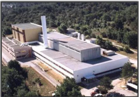
The LECA-STAR nuclear facility (pictured below) is located at the CEA Cadarache centre (in the south of France). It was built to perform R&D activities on irradiated nuclear fuels.
The LECA-STAR hot cells and microanalysis laboratory are used for transforming fuel rods and conducting tests and destructive or non-destructive examinations on fuel irradiated in different industrial reactors or research reactors.
These ongoing activities support the start-up of the future experimental reactor JHR on the Cadarache site. Currently, the LECA-STAR R&D activities continue to meet the needs expressed by the CEA and its industrial partners. Some ageing equipment is being replaced (SEM, optical microscope, cutting machines, drilling machines, etc.) and new equipment is being installed (NDE or cutting bench, etc.) to maintain the laboratory at the required level of excellence. These operations are being carried out by a dedicated installation laboratory.
2 Laboratory set-up and skills
A dedicated laboratory - the nuclear engineering experimentation laboratory (LIEN) - has been set up to optimise project management processes and leverage operating experience. This laboratory is responsible for the research, development, fabrication and testing of new equipment intended for use in hot cells.
The laboratory’s project managers are in charge of test bench development, managing the process right the way through from the statement of requirement to acceptance of the equipment. The laboratory therefore offers a wide range of cross-functional competencies to meet the typical technical requirements of the projects it handles:
project management
Planning
Mechanical design (CAD)
Electrical and I&C system design
Mechanical, thermal and fluid calculations
Radiation protection calculations
The laboratory also has a cold mock-up of a real cell equipped with a master-slave manipulator arm for testing equipment remotely.
In an effort to develop equipment as effectively as possible, the lab has embarked on a process of standardisation at both an organisational and a technical level. This undertaking is explained below.
3 Development process
Although all equipment developed at the laboratory are different, the LECA-STAR facility has implemented a “standard” organisational structure which allows projects to be managed in such a way as to limit the risks involved.
A project involves two main parties: the applicant and the project manager.
The applicant is the end user of equipment being developed, who can be supported, if necessary, by a operator.
The project manager is the person in charge of the equipment development for the applicant. He is supported by all the technical skills offered by the laboratory (mechanical design, electrical design, I&C system design, etc.).
It is recommended that both these individuals are formally identified at the outset. A document written at the start of a project identifies the roles and responsibilities of everyone involved at each stage of the project. The usual process for developing a test bench for use in a hot cell is described below.
3.1 Statement of requirement stage
This stage is completed by the applicant who expresses the requirement as fully and precisely as possible, specifying the operations to be performed, the type of objects to be handled and the expected performance (mechanical, measurement), for example. At this stage it is recommended that the statement of requirement includes only functional requirements.
3.2 Feasibility study stage
This stage is completed by the projet manager (in-house at the laboratory in the majority of cases) who can draw on the lab’s specific competencies (notably CAD skills). The purpose of this study is to provide a preliminary design of the equipment to illustrate the solution developed to meet the functions requested in the statement of requirement. This solution must also incorporate the technical constraints as well as the various constraints associated with the operating environment, remote operability and safety, etc.
Depending on the conclusions of this study, the initial requirement may be revised. This revision will be made in consultation with the applicant. The feasibility study must ultimately be approved by the applicant.
It is highly recommended that this stage be completed before launching a tender process to manufacture the equipment. Operating feedback shows that specifications drawn up on a purely functional basis are more likely to experience technical difficulties at some point during the project, which could cause infeasibilities or significant degradation of desired performance.
Once the feasibility study is complete, a specification is generally drawn up for the purpose of the supplier tendering process. It is recommended that the specification reiterates the functional requirements and associated performance and that it presents the technical solution under consideration for information purposes. The specification collates and summarises all requirements relating to the following:
functions
performance
safety
maintenance
in-cell operability
acceptance criteria, which must be defined at this stage and agreed by the applicant
In addition to the technical criteria, the specification defines the requirements in terms of planning, studies, fabrication, testing and acceptance, etc.
It is highly recommended that the overall functional scope of the equipment is specified in the contract with the supplier.
The laboratory has a generic guide/template for drafting a specification to ensure that all the important points relating to a specific project are covered, thereby ensuring the completeness of the approach. This means, for example, that the cross-functional requirements (technical specifications,
studies, fabrication and testing requirements) are the same for all contracts, which helps to standardise practices in the laboratory. It also means that all documentation supplied with the end product are standardised as well.
This template acts as an aid for project managers when specifying their requirements throughout all stages of the project.
3.3 Developing the equipment
Once the project manager has selected the supplier, the project then moves into the detailed design stage. The feasibility study conducted by the laboratory usually serves as the starting point for the supplier, however, they are free to adapt or modify it based on their experience, competency or production tool.
Once the detailed design studies have been completed and before moving on to the manufacturing phase, the project is reviewed comprehensively by the various stakeholders, such as the project manager (responsible for organising the review), applicant, safety engineer and operators, etc. This review stage allows all the studies conducted by the supplier to be formally approved before commencing fabrication.
The equipment construction and assembly operations in the factory are monitored by the project manager.
3.4 Factory testing and acceptance stages
The factory acceptance and testing stages are prepared by the project manager who checks, by means of a specific supplier testing programme, that the specified performance has been reached. The applicant is also present during these tests to familiarise himself with the equipment.
3.5 Cold qualification stage
This stage is usually carried out in the mock-up cell where test bench operation, setup/dismantling, repair and standard and exceptional maintenance operations are tested remotely. The aim here is to ensure the operability of the equipment in the most realistic simulated hot cell environment possible.
These tests are conducted by the applicant or their delegated operators being trained on how to use the bench in a cold cell. The project manager monitors the progress of the tests and intervenes if necessary with the supplier. It is essential at this stage that the operators are provided with the operating and maintenance instructions that will serve as the working documents during equipment operation.
All aspects of remote operability are definitively approved at this stage. They are examined at three different points throughout the project: at the CAD modelling stage, the factory testing stage and finally during the mock-up tests. Feedback at each of these stages is used to make improvements to enhance operator comfort for each of the manipulation actions to be carried out.
3.6 In-cell installation and operation
This last stage of the process is normally completed by the applicant and monitored and supported by the project manager. Once the test bench in installed in the hot cell and connected up, a final test phase is completed to check that performance remain the same post-installation.
4 Technical specification editing
The laboratory has set up a technical specification editing programme as a means of standardising technical content that is common to different R&D projects. These specifications are designed to be applied to all projects handled by the laboratory and include the following guidelines:
4.1 CAD drawings and design guidelines
This specification describes the architecture for the CAD models which must be followed by companies completing the CAD designs on behalf of the laboratory. It defines, for example, the logistical hierarchy of the various components, the numbering rules for files and CAD model assemblies, plant classification rules, and the masks and layers to use, etc.
This ensures that all CAD models are standardised and can be incorporated easily into an overall design for a particular cell for instance.
4.2 Mechanical construction rules
This specification applies to “simple” mechanical equipment constructed on behalf of the facility, and which is not governed by a specific mechanical construction code. This document includes a description of the following:
The reference standards applicable to the supplies (steel or stainless steel) and the level of material certification required,
The welding requirements in terms of operator qualification, process qualification, type of welding inspection required according to type of weld and the permissible defects, etc.
Requirements relating to the dimensional inspections to be conducted,
The surface treatments and cleanliness grades to be applied.
4.3 Seismic design hypothesis and methodology
This specification applies to all seismic design calculations completed for new equipment. It defines the following:
The acceptable calculation method(s) (spectrum, pseudo-static) and the accepted software
The applicable mechanical design criteria according to the behaviour requirements, depending on the initial safety requirements (stability, integrity). There are defined mechanical design criteria provided by the RCC-M code.
The properties of the materials used in the calculations
The anchoring principles and the bolt design calculation methods
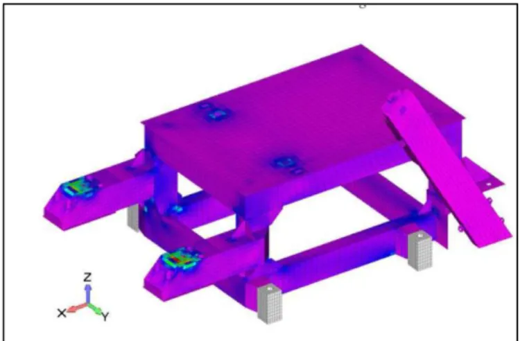
Figure 2: Seismic design calculation for a shielded cask docking table
4.4 Radiation protection calculation guidelines
This specification applies to the radiation protection design calculations for new biological shielding at the LECA-STAR facility. It defines:
The envelope source term to be used for the LECA-STAR facility for each radionuclide and energy spectrum
The permissible calculation methods (deterministic or probabilistic) based on the applications considered
The applicable dose rate criteria depending on whether the source is present constantly, whether there is a workstation, etc.
The properties of the materials used in the calculations
The mandatory information that must appear in the calculation sheet
4.5 Construction guidelines for biological shielding penetrations
This specification defines the drawings for the standard penetrations and the different configurations that will be valid for the LECA-STAR facility (i.e. penetrations for fluid or electrical circuits). It also defines:
The different authorised electrical or fluid connectors or valve glands allowed
The penetration construction principles (dimensional tolerances, surface condition, coating, etc.)
The tightness criteria
The lead ball filling criteria required prior to installation of the facility
The tests to be conducted in the factory (tightness) and after the cell has been installed (tightness, biological shielding)
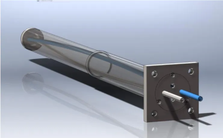
Figure 4: 3D view of a LECA cell penetration
4.6 Guidelines for the use of electrical and fluid connectors in hot cells
This specification defines the connectors which can be used in hot cells. In terms of electrical connectors, the LECA-STAR facility uses mainly SOURIAU (previously referred to as JUPITER) or LEMO remote handling sockets. The specification also defines the in-cell socket identification, mounting and wiring principles.
STAUBLI remote handling sockets are used for the fluid connectors. The specification defines which connectors should be used according to their application in the cell (gas, pressure, vacuum, etc.) and the mounting principles.
4.7 Guidelines on which seals and plastic materials can be used in hot cells
Although the use of plastic, rubber or polymer materials should be avoided in hot cells (due to the accelerated ageing effect and the risk of criticality caused by their hydrogenated nature), some requirements mean that materials of this kind need to be used. This is the case with seals and sliding parts, for instance.
The specification therefore gives the different types of polymer available on the market and their resistance to irradiation, hazardous chemical compounds and temperature to be able to find the best solution for the application in question.
4.8 I&C system design principles (on progress)
Design and construction guidelines are drafted to standardise the I&C systems for all the different equipment present in a facility and to facilitate maintenance. These specify:
The preferred architecture to be used for the IT systems
The different programming languages permitted
The programme development logic and the different stages of the process to be included
The principles for the graphical user interface
5 Examples of recent projects
This section describes some of the equipment developed recently for operation in hot cells.
5.1 Rod cutting bench
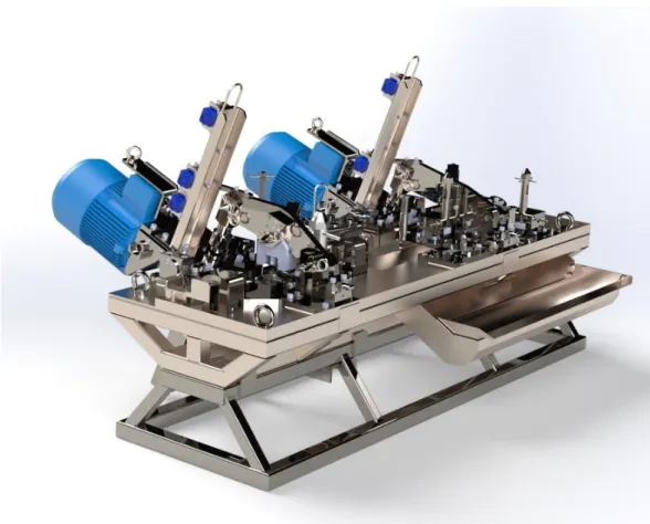
This bench is designed to cut fuel rods so that they can be repackaged in waste disposal containers. It is used in the repackaging process for spent fuel. The bench has the following features for cutting the fuel rods:
Two high power shears driven by ball screws for cutting solid fuel rods easily
An automatic feed and clamping system
A collection system for the cut end pieces
Figure 5 : fuel rod cutting bench
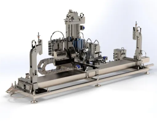
5.2 Non-destructive measurement bench for fuel plates
This bench is used to conduct a number of non-destructive examinations on fuel plates. It features the following functions:
Plate length, thickness and profile measurements
These measurements are taken using high precision measurement cassettes equipped with LVDT sensors. By moving these cassettes along the plate, length and thickness measurements can be taken
(by two LVDT sensors mounted opposite each other) as well profile measurements. The plate thickness measurements are accurate to within 0.01 mm.
Gamma spectrometry measurements
Using a gamma spectrometry detector installed outside the hot cell and a dedicated penetration for the collimation system, the plate is fed along the bench in front of the penetration to acquire the different X-ray lines and energy levels of the fuel plate.
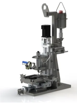
5.3 Microsampling machine
This instrument is designed to take core samples from fuel pellets.
The minimum and maximum core diameters are 1 mm and 4 mm respectively. The motor can rotate at speeds up to 50,000 rpm. The lowering speed can be set as low as 0.01 mm/s.
Ethanol is used to cool and collect the fuel sludge. Once the pellet has been pierced by the core sampler, the core sample is placed carefully in a crucible to be taken away for analysis.
5.4 Plate cutting bench
This precision cutting bench is designed for cutting fuel plates to isolate the fuel zones.
It features a fuel space detection system based on an eddy current probe which is used to correct the position and angle of the fuel plate automatically to align the cutting disc with the gap between the fuel plates with 0.1 mm accuracy.
The plate is cut using a 0.5 mm thick diamond cutting disc.
Figure 8: 3D view of the fuel plate cutting bench
Conclusion and summary
The setup at the LECA-STAR facility with the nuclear engineering experimentation laboratory (LIEN) provides the opportunity to continue to leverage the operating experience acquired during the development of benches intended for use in hot cells.
This operating experience also helps to mitigate the risks associated with current and future developments. It covers organisational aspects (at laboratory and/or project level) as well as technical aspects (technical specification editing) and project management methodology.