HAL Id: cea-02509680
https://hal-cea.archives-ouvertes.fr/cea-02509680
Submitted on 17 Mar 2020HAL is a multi-disciplinary open access archive for the deposit and dissemination of sci-entific research documents, whether they are pub-lished or not. The documents may come from teaching and research institutions in France or abroad, or from public or private research centers.
L’archive ouverte pluridisciplinaire HAL, est destinée au dépôt et à la diffusion de documents scientifiques de niveau recherche, publiés ou non, émanant des établissements d’enseignement et de recherche français ou étrangers, des laboratoires publics ou privés.
The future Jules Horowitz Material Testing Reactor: A
way for developing international collaboration around a
major European irradiation infrastructure
Daniel Parrat, G. Bignan, B. Maugard, C. Gonnier, C. Blandin
To cite this version:
Daniel Parrat, G. Bignan, B. Maugard, C. Gonnier, C. Blandin. The future Jules Horowitz Material Testing Reactor: A way for developing international collaboration around a major European irradia-tion infrastructure. WWER Fuel 2015 - 11th Internairradia-tional Conference on WWER Fuel Performance, Modelling and Experimental Support, Sep 2015, Varna, Bulgaria. �cea-02509680�
1
11th International Conference on WWER Fuel Performance, Modelling and Experimental Support
26 September – 03 October 2015, Golden Sands Resort, Varna, Bulgaria in co-operation with the International Atomic Energy Agency
THE FUTURE JULES HOROWITZ MATERIAL TESTING REACTOR:
A WAY FOR DEVELOPING INTERNATIONAL COLLABORATION AROUND
A MAJOR EUROPEAN IRRADIATION INFRASTRUCTURE
D. Parrat(*), G. Bignan, B. Maugard, C. Gonnier, C. Blandin
(*)Main author address: CEA, DEN, DEC/SESC, Building 151, CEA Cadarache
F – 13108 Saint Paul lez Durance, France T: +33-442-257-572 F: +33-442-254-747
Mail: [email protected]
ABSTRACT
Development process of a fuel product or a nuclear material before using at an industrial scale in a power reactor ranges from characterization of the material itself under neutronic flux up to its qualification in accidental conditions. Irradiations in Material Testing Reactors (MTRs) are in practice the basis of the whole process, in complement of prediction capabilities gained by modelling. Dedicated experimental reactors play also an important complementary role for some specific integral tests (e.g. RIA tests). Irradiations of precursors in power reactors are often limited to products which present a slight design evolution compare to the standard product or are implemented when a statistical approach is useful for defining a safety criterion. However European MTR park status is characterized by ageing infrastructures, which could cause operational issues in coming years, either on technological or on safety point of views. Moreover some specific supplies related to the public demand could be strongly affected (e.g. radiopharmaceutical targets). To avoid a lack in irradiation capacity offer at European level, CEA launched the Jules Horowitz Material Testing Reactor (JHR) international program, in the frame of a Consortium gathering also EDF (FR), AREVA (FR), European Commission (EU), SCK.CEN (BE), VTT (FI), CIEMAT (SP), STUDSVIK (SE), UJV (CZ), NNL (UK), IAEC (IL), DAE (IN) and as associated partnership: JAEA (JP). Some institutions in this list are themselves the flagship of a national Consortium. Discussions for enlarging participation are on-going with other countries, as JHR Consortium is open to new member entrance until JHR completion. The Jules Horowitz Material Testing Reactor (JHR MTR) is under construction at CEA Cadarache in southern France and will be an important international User Facility for R&D in support to the nuclear industry, research centres, regulatory bodies and TSO, and academic institutions. It represents a unique and extremely favourable situation for which future end-users can express very early their needs, thanks to either participation to the JHR Consortium, or to international programs or through bilateral collaborations.
A general presentation of this research infrastructure and associated experimental capability has been made at the 9th WWER Fuel Performance Meeting in 2011. Current paper updates in a first part the facility
building status and the current design work carried out on irradiation hosting systems for nuclear materials and nuclear fuels and on non-destructive examination benches. Then expected main performances are reviewed and collaborations set up around each study are also underlined, as they often correspond to an “in-kind” contribution of a Consortium member. Finally, recent developments in the international co-operation around the facility are highlighted, such as for example the CEA candidacy for the IAEA designation as an ICERR (International Center based on Research Reactors) or the numerous staff of secondees working on-site.
KEYWORDS: CEA, Material Testing Reactor, Jules Horowitz Reactor, Irradiation device, JHR consortium, ICERR.
2
1. INTRODUCTION
Material Testing Reactors (MTRs) are now key infrastructures, in complement of prediction capabilities gained by modelling, for supporting nuclear energy in terms of safety, ageing management, innovation capacity, economical performances and training. In this frame, they have provided an essential support for nuclear power programs over the last 50 years within the European Community. MTRs address development and qualification of materials and fuels under irradiation with sample sizes and environment conditions relevant for nuclear power plants in order to optimize and demonstrate safe operations of existing power reactors as well as to support future reactors design. In addition, for most European countries, keeping competences alive is a strategic cross-cutting issue, and developing and operating a new and up-to-date research reactor appears to be an effective way to train a new generation of scientists and engineers.
However, the large majority of European Material Testing Reactors (MTRs) will be more than 50 years old this decade, leading to the increasing probability of some shutdowns for various reasons (life-limiting factors, heavy maintenance constraints, possible new regulatory requirements, experimental facility obsolescence…). Moreover some specific supplies related to the public demand could be strongly affected (e.g. radiopharmaceutical targets). Such a situation could not be sustained on the long term. This analysis was already made by a thematic network within the Euratom 5th Framework program (FP), involving experts
and industry representatives, in order to answer the question from the European Commission on the need for a new MTR in Europe [1] [2], and a consensus has been drawn on the strategic need to renew MTRs in Europe [3] [4]. This preparatory work lead to the fact that the Jules Horowitz material testing reactor (JHR) research infrastructure has been identified on the European Strategy Forum on Research Infrastructures (ESFRI) Roadmap since 2008.
2. UPDATE OF THE JHR PROGRAM STATUS
A general presentation of the JHR programme and of its main characteristics has already been made at the 9th
edition of the WWER Fuel Performance conference in 2011 [5], but other recent presentations also exist [6]. Present paragraph firstly resumes objectives and main characteristics of the reactor then is mainly focussed on the programme update regarding the infrastructure itself (civil works and common equipment).
2.1 Reminder of JHR objectives This new MTR will in priority:
• Implement experimental R&D programs in support to nuclear industry:
o Fuel optimization, plant life-time management and safety improvements for ageing and new power reactors, in relation with modelling needs,
o Fuel and nuclear materials behavior studies in incidental and accidental conditions, o Innovation assessment and related safety for future power systems.
• Supply radio-isotopes for medical applications: the JHR will supply 25% of the European demand for diagnoses using 99Mo (today about 8 million protocols/year) on basis level. This supply will go
up to 50% of the European demand in case of specific request. • Support expertise by:
o Training of new generations of scientists and operators (JHR simulator, secondees program…), o Maintaining a national high level expertise staff and credibility for public acceptance,
o Assessing safety requirements evolution and international regulation harmonization.
2.2 Brief overview of JHR main characteristics
JHR core is a high power density fuel rack in a vessel slightly pressurized, cooled by light water and surrounded by a reflector made of beryllium blocks located in the core pool (see figure 1). Core is designed for a power of 100 MWth and is optimized to produce high fast neutron flux to study structural material ageing and high thermal neutrons flux for fuel behavior studies (see more details in § 4.1). At nominal operation JHR is to operate with 10 cycles a year (representing about 260 Equivalent Full Power Days). JHR fuel will be U3Si2 dispersed into an aluminium matrix, with a load of 4.8 g U/cm3 and a 235U enrichment
varying from LEU up to a maximum of 27% optimizing the loading of the reactor. UMo fuel dispersed into aluminium may replace later on it, when industrially qualified for JHR performances and available. Its load
3
will be 8 gU/cm3, with a 235U enrichment lower than 20% (LEU). This fuel is being developed within an
international collaboration [7].
Figure 1: Global view of the JHR reactor block and detailed view of the core
2.3 JHR civil works update
Construction is currently under progress at CEA Cadarache Centre. Engineering studies were devoted to AREVA group subsidiary AREVA-TA, which ensures the supervision of the construction site, and is also in charge of providing key reactor components. Some illustrations of undergoing construction activities are provided on figure 2 below.
December 2013: Reactor dome installation © CEA Early 2015: View of Reactor and Auxiliary Unit Buildings© CEA
January 2015: Reactor dome concrete poured © CEA April 2014: Reactor pool internal structures © CEA
Location in
reactor core Reactor tank
Berylium blocks Location in Berylium reflector Location for displacement device Reactor block Fuel Element
4
January 2015: Global view of Hot Cells mounting (in-kind supply of UJV, CZ) © CEA
Figure 2: Progresses on the JHR building site
More than twenty other suppliers in the fields of civil works, mechanics, heating, ventilation, air-conditioning, electric components… contribute to the construction of the facility. An important milestone has been reached in December 2014, with the success of Detailed Design Review of the reactor block, authorizing starting of the realization phase for this component (see figure 1). Other important steps for large components manufacturing on installation preparation have been recently done or started: polar crane reception tests, pools metallic liner anchoring on concrete, preparatory work for the Reactor Building pre-stress by cables, manufacturing of the first primary heat exchanger etc. At the present time, JHR first criticality is foreseen second part of 2019 and plan to be in operation by end of 2020.
3. JHR OPERATION PREPARATION 3.1 JHR operation management
JHR program, as a future international User Facility, is funded and steered by an international Consortium gathering industry (utilities, fuel vendors…) and public bodies (R&D centers, TSO, regulator…). The generic model of JHR Consortium is the following:
• CEA remains the owner and the nuclear operator of the nuclear facility with all liabilities,
• JHR Consortium Members are the owners of Guaranteed Access Rights to the experimental capacities in proportion to their financial commitment to the construction and with a proportional voting right in the Consortium Governing Board,
• A Member can use totally or partly his access rights for implementing proprietary programs with full property of results and/or for participating to multilateral programs with few members (e.g. for WWER needs), or the Joint International Programs open to non-members,
• JHR Consortium membership is open to new members until completion of the reactor.
As of mid-2015, member’s list of JHR Consortium is: CEA (France), EDF (France), AREVA (France), European Commission-JRC, SCK•CEN (Belgium), UJV (Czech Republic), VTT (Finland), CIEMAT (Spain), Studsvik (Sweden), DAE (India), IAEC (Israel), NNL (United Kingdom). There also exists an implementing agreement between CEA and JAEA (Japan) with a view to access to JHR. Some institutions in this list are themselves the flagship of a national Consortium (e.g. VTT for Finland, CIEMAT for Spain and NNL for UK). Discussions for enlarging participation are on-going with other countries.
3.2 JHR safety update
As a new-built facility, JHR incorporates safety analysis right from the design phase, based on a modern reference system and methodologies. These can be related to those used in contemporary projects such as the EPR GEN3 NPPs under construction, but adapted to characteristics and situation of a research reactor project. JHR Safety approach was presented in detail at the IAEA General Conference on Research Reactors in Rabat last November 2011, with some examples of incorporating safety from the design phase [8].
Following the Fukushima-Daichi accident (March 2011), the French Nuclear Regulator (ASN) also asked CEA to perform complementary safety assessments to meet objectives under extreme situations exceeding licensing basis (with focus on “cliff-edge” effect prevention). These complementary assessments basically confirmed the sound design bases of the newly built JHR. A few selected needs for extra equipment were
5
also identified, and, as an answer to ASN requirements, CEA proposed a set of “hardened core” measures (e.g. with a view to ultimate cooling capacity, to ultimate sensors, ultimate valve actuation or associated ultimate battery and generator set).
3.3 JHR operation as an international User-Facility
Parallel to construction of the reactor, preparation of an international community around JHR is continuing. This is an important topic because, as already indicated, building and gathering a strong international community in support to MTR experiments is a key-issue for the R&D in nuclear energy field.
3.3.1 Building international joint programs
According to the Consortium agreement, JHR is aimed to become a user reactor at international level (similar to OECD/Halden Reactor Project) with multinational project and proprietary experiments. As anticipated preparatory actions, the JHR Consortium has set-up a yearly scientific Seminar and three Working Groups (Fuel, Material and Technology) to identify R&D topics of common interests and to prepare the first international joint programs addressing fuel and material key issues (mainly focused on LWR). Three meetings of these groups have already been held from 2013, partly with joint sessions, and a first common “synthesis document” (memo) for the Governing Board is planned to be released at the end of 2015. This document will introduce a future more complete “position paper” (roadmap document) to be released in 2016 indicating potential experiments in existing research reactors in preparation of JHR experiments.
3.3.2 Academic opportunities and training
The JHR experiment team at Cadarache is already welcoming scientists, engineers (called Secondees) from various organizations/institutes who are integrated within the team for a limited period of time (typically one year) for various topics such as physics studies for the development of the experimental devices (neutron physics, thermal-hydraulics…) and/or for support to the future operator (Safety Analysis, I&C…).
This Secondment Program is an important topic for countries willing to invest in nuclear technology helping them to create and sustain key competences. In fact, between academic training and “commercial training linked to a product”, there is a need for nuclear education “in the field” using modern high-performance infrastructures dedicated to the training of future senior scientists, engineers… for the benefit of decision-makers in countries wishing to develop nuclear energy. The JHR Secondment Program is giving such nuclear education that offers direct experience of working in nuclear facilities and provides training opportunities that fill the gap between academic education and commercial-product specific training.
3.3.3 CEA candidacy for designation to be an International Centre based on Research Reactors (ICERR) The previous point is fully compliant with the recent IAEA initiative on establishing labellized International Centre based on Research Reactors (ICERR) in order to rationalize the research reactors fleet worldwide and to harmonize Operation and Safety. This initiative was approved and announced by Director General Yukiya Amano in his introductory statement to the IAEA Board of Governors, on September 15th, 2014.
For that aim, and due to its long experience in operating and using research reactors and in receiving foreign collaborators in its facilities, CEA has decided to be candidate to its designation as an ICERR. The perimeter proposed to be included in the ICERR in centered on the JHR, associated with some important ancillary facilities including state-of-the-art hot cell laboratories for fuel and materials post-irradiation examinations (LECI in CEA Saclay and LECA-STAR in CEA Cadarache), existing low/zero power reactors for core physics, education and training (ISIS, EOLE, MINERVE) and the neutron beam ORPHEE reactor for basic science. Objective is that CEA ICERR designation is to be officially announced by the IAEA during its next general Conference in September 2015.
3.4 JHR operation preparation: Commissioning and licensing files
Preparation of future JHR commissioning tests, as of operation tests before JHR commercial starting, is now in the scope of some JHR teams, which have been structured and reinforced with that aim. Preparatory work has started and concerns on one hand technical set up of tests, such as:
6
• Development of experimental mandrels for precise irradiation locations characterization versus fast and thermal neutron fluxes or gamma heating levels,
• Definition of acceptance tests regarding fuel and materials irradiation devices (linear power and/or dpa reachable on samples, sample cooling, thermal balance quality etc.).
However work also concerns licensing files: after issue of the Preliminary Safety Report (RPrS), Interim Safety Report (RPS) is under construction. Preparation of reactor operation rules are also in progress. More details on these tasks are presented in [9]
.
4. JHR EXPERIMENTAL CAPACITY: IRRADIATION HOSTING SYSTEMS
A general presentation of the JHR experimental capacity has been made several times [5], [10], in relation with experimental program needs [11]. Present paper focusses on expected experimental performances and highlights last developments of this capacity. It also deals with new irradiation devices recently designed by Consortium members as their “in-kind” contribution.
4.1 Area and components dedicated to irradiation experiments
One half of the JHR reactor building is dedicated to implementation of equipments in support to in-pile irradiations (for example water loops). This corresponds to 700 m2 over 3 floors for implementation of
experimental cubicles and 490 m2 over 3 floors for instrumentation and control equipments. An additional
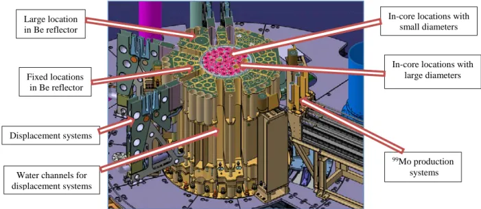
area is devoted to analysis laboratories (see § 5.2). Design of the reactor core allows implementing up to 20 simultaneous experiments with a large range of irradiation conditions (see figure 3):
• 7 in-core locations with small diameter (32 mm, in the central hole of a JHR fuel element) with a high fast flux (up to 5.5 1014 n.cm-2.s-1 perturbed flux above 1 MeV, and up to 16 dpa/year on a
sample, reactor with UMo fuel at 100 MWth). These locations can be either on the “first row”, or “second row” or “third row” (from the core center) offering different flux values,
• 3 in-core locations with large diameter (80 mm, in place of a JHR fuel element) with a high fast flux (up to 4.0 1014 n.cm-2.s-1 perturbed flux above 1 MeV). One location per row is planned,
• 20 fixed positions in the Beryllium reflector (about 100 mm of diameter and one location with 200 mm) with a high thermal flux (up to about 3.0 1014 n.cm-2.s-1 perturbed flux),
• 6 positions on displacement systems through the Beryllium reflector (up to about 3.5 1014 n.cm-2.s-1
perturbed flux).
Figure 3: Irradiation locations in JHR core and reflector (schematic cross-cut)
Main LWR fuel irradiation devices (also called “hosting systems”) are located on displacement systems in the Beryllium reflector. These systems can move forwards and backwards from the core tank. Consequently they allow an accurate fuel sample linear heat rate control and can reproduce complex linear power time histories. Maximum velocity tolerated towards the reactor core is 5 mm/s. Velocity control allows carrying out high quality power ramp experiments (up to 700 W.cm-1.min-1) even for very high burn-up fuels (100
In-core locations with small diameters
Displacement systems Large location in Be reflector
In-core locations with large diameters Fixed locations
in Be reflector
99Mo production
systems Water channels for
7
GWd/t). Design of the displacement device allows also a quick withdrawal velocity (50 mm s-1) towards its
safe back position. Such a concept is convenient for the operation (load/unload the experiment even during the operating cycle) and for the safety (the safe back position and the off normal conditions of the device are not directly coupled to core operations). Design of this system is currently in progress.
4.2 Irradiation hosting systems available at the JHR start-up
4.2.1 MADISON device: Comparative instrumented fuel irradiations in normal conditions
This experimental device will carry out irradiations of LWR fuel experimental rods (up to 60 cm fissile stack) when no clad failure is expected. Experimental conditions correspond to normal operation of power reactors (steady states or slow transients). It is made of an in-pile part (holding the fuel samples) situated on a displacement system. This part is connected to a water loop implemented in a dedicated cubicle and providing thermal-hydraulics conditions expected for a given experimental program (PWR, BWR or WWER technologies), with water loop pressure up to 160 bar and temperature up to 320°C.
A specific chemical analysis system and a water treatment system allow continuous regulation of chemical conditions. Usual chemical conditions of power plants can be reproduced as well as specific chemical conditions (depending on customer needs).
First irradiation sample-holder (“rig”) version has a carrying capacity of 4 fresh or pre-irradiated instrumented samples (with a maximum of 2 sensors per sample) placed on a row. It will be also flexible enough to operate with 2 highly instrumented samples (with cumbersome instrumentation such as on-line clad diameter measurement). For that purpose, 5 tight high temperature and pressure connectors are implemented on the sample holder to allow the plug-in of specific sensors. Following instrumentation can be used in the first MADISON sample holder manufactured for the JHR start up: fuel central temperature, clad temperature, clad elongation, fuel stack elongation, fuel plenum pressure and fission gas release composition based on acoustic measurement device.
Other sensors are dedicated to the water loop and measure on-line thermal-hydraulics conditions (pressure, temperature, water flow, chemistry), and neutron flux conditions (thermal neutron flux, fast neutron flux). In addition, the design of the test section allows on-line measurement of thermal balance in the test section that provides a fuel samples linear power with a targeted 5% accuracy.
A second version of the MADISON sample holder is under investigation and is based on the previous one, but will be limited to two rod samples when equipped with a diameter gauge.
First rig will embark a heat exchanger to be able to implement BWR experiments (see figure 4) and will be used for commissioning tests at JHR start-up (confirmation of neutronics and hydraulic performances).
Figure 4: MADISON hosting system: Schematic of the first irradiation rig
IFE (Institute for Energy, Halden, Norway) is contractually in charge of the detailed design, manufacturing and assembly in JHR site of most components from this experimental device, to account for the large feedback of this Institute in the building of water loops, irradiation rigs and in-core instrumentation. Detailed design phase is in progress and the Detailed Design Review (DDR) is planned with IFE beginning of 2016. Design of few other main components is in charge of CEA: call for tender for detailed design, manufacturing and assembly on site of the cubicle box is planned to be released mid-2015, and call for tender of the in-pile pressure flask is expected late 2015.
4.2.2 ADELINE device: Characterization and qualification of a single fuel rod in incidental conditions The ADELINE device is able to test a single experimental fuel rod from all LWR technologies in various experimental irradiation scenarios where clad failure is either a risk or an experimental objective. Similarly
8
to the MADISON experimental device, this experiment is made of an in-pile part and an out-of-pile water loop. Fresh or pre-irradiated fuel rods will be used to perform:
• Power ramp tests,
• Rod internal over-pressurization (“lift-off”), • Rod internal free volumes gas sweeping, • Power to melt approach margin mastering.
First version is in priority dedicated to power ramps testing and is developed thanks to EDF support. The objective is to continue the service offer and to operate with an experimental quality at least as good as the one currently offered by the ISABELLE 1 loop in the French Material Testing Reactor OSIRIS. In particular, design of this device is optimized to provide a qualified thermal balance and a good accuracy on the clad failure instant and consequently a good knowledge of the linear power inducing the failure. A quantitative gamma spectrometry system will allow quantifying on-line the radiological source term released in the coolant when a rod fails.
Experiment quality is targeted thanks to the in-pile instrumentation that provides a good accuracy of the thermal balance: based on a differential temperature measurement greater than 20°C between upstream and downstream from test section, a 5,7% uncertainty (2σ) on the final value of the linear power during the ramp upper plateau is expected. In addition, during a power ramp, the displacement device and the control system will guarantee that the targeted final measured linear power will have a ± 10 W/cm accuracy at 620 W/cm. Some enhancements are added in order to make on-line quantitative clad elongation measurement during power transients and to manage several successive experiments during one JHR cycle. In a longer term, a second version will be dedicated to study of long-term post-failure behavior in normal conditions (failure evolution, secondary hydriding, release of fission products and of fissile material…), coupled with the JHR Fission Product Laboratory (see § 5.2).
The kick-off meeting for launching the detailed design, manufacturing, assembly and tests on site of the full hosting system was held in November 2014 with the contractor. Detailed design phase is now on-going. 4.2.3 MICA device: Investigation of materials physical properties under neutron flux
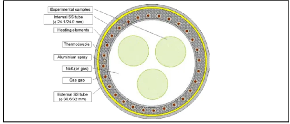
The MICA test device is designed to irradiate structural materials (neither fissile nor fertile). The experimental samples are targeted for a large number of JHR irradiation cycles. The current MICA version under development is designed for irradiation in the JHR core, and the in-pile part is placed in the central hole of a fuel element (see figure 5).
Figure 5: Section of the MICA device experimental area
For a “low-temperature” irradiation configuration, target temperature range for the experimental samples is 280°C – 350°C (maximum temperature of 450°C). This configuration is reached by immersing the experimental samples in a bath of static liquid metal (mixture of Na and K) which ensures the thermal homogeneity of the environment. In the “high-temperature” configuration, the samples can be placed in an environment up to 700°C. A specific study must be conducted if this temperature needs to exceed 1000°C. In this high temperature configuration liquid metal is replaced by a neutral gas which is chosen on the basis of the required thermal performance.
Once the reactor has reached nominal power, nuclear heating in the core transfers energy to the MICA and thus to the experimental load, which is equivalent to about 15 to 35 kW depending on the reactor power, the location of the MICA in the JHR core, and the experimental load in the MICA. This generates a temperature
9
rise through a thermal insulation provided by a gas gap between the 2 concentric tubes of the MICA containment. To reach the required temperature level, additional power is provided by means of 6 electrical heaters (between 0 and 15 kW), placed on the internal tube, axially mounted and embedded within an aluminium spray. Injected power is controlled to meet the thermal stability criteria. When the 6 heaters are switched on (even at different power supplies), the radial gradient of temperatures is strongly reduced (less than about 5°C).
Three MICAs are planned at the start of JHR commercial operation Detailed design phase is in progress at CEA. Call for tender, for manufacturing and on-site tests, is planned at the end of 2015.
A sophisticated sample-holder compatible with MICA, called MELODIE, has been developed in the frame of a VTT - CEA collaboration. It aims at study LWR cladding irradiation creep thanks to a real time control of the applied biaxial stress (axial and circumferential), with on-line separate measurement of the biaxial creep. A first irradiation cycle has been carried out in the OSIRIS MTR in May 2015.
4.3 Main irradiation hosting systems available after the JHR start-up (limited list) 4.3.1 LORELEI test device: Single rod behavior during a LOCA-type sequence
The purpose of LORELEI device is investigating the behavior (thermal-mechanical and radiological consequences) of LWR-type pre-irradiated fuel rods under Loss Of Coolant Accident (LOCA) conditions. The thermal-hydraulic phenomena does not reproduce all phases of a realistic LOCA-type power reactor sequence (in particular the first clad temperature peak), but the thermal-mechanical conditions (clad temperature, clad over-pressure, steam environment) will be representative.
This equipment consists in an integrated water capsule, operated as a thermo-siphon, able to re-irradiate a single pre-irradiated and instrumented fuel sample, mainly for producing a short half-life Fission Product (FP) inventory. For the first version of the test device, the re-irradiation power is low (a few tens Wcm-1).
In-pile part is equipped with a gas injection able to rapidly empty the test device in order to simulate the dewatering and the dry-out phase of the fuel rod during LOCA transient. A neutron shielding can be used to flatten the axial neutron flux profile. An electrical heater implemented in the sample holder allows getting a homogeneous temperature azimuthal distribution and acts as a dynamic thermal insulation in order to get representative adiabatic conditions (initial heat-up rate ranges typically between 10 to 20°C/s). The high temperature plateau (up to about 1200°C) will be monitored by adjusting the rod nuclear power with the displacement system (and by switching-off electrical heater) in order to prevent any temperature escalation. At last, low temperature water can be re-injected in the device to simulate the quenching process. More details on the device and its instrumentation are in [12].
This device allows investigating ballooning and burst of the fuel cladding (the inner pressure of the refabricated fuel rod can be chosen for that purpose), clad corrosion phenomena (oxidation and hydriding), quenching, post-quench behavior, fissile stack fracturation, fission product and fissile material release and dispersal. To that last purpose, the device will be connected to the JHR Fission Product Laboratory. Some additional components (e.g. grid springs, surrounding rod array simulation etc.) are planned to be added to get more representative solicitations applied to the tested rod or the environment.
Design and manufacturing of the test device are made in collaboration with the Israel Atomic Energy Commission (IAEC), as in-kind contribution. Preliminary Design Review was held early 2014. Detailed design phase is in progress and Detailed Design Review is planned early 2016. Test device operation is expected just after JHR start-up.
4.3.2 OCCITANE test device: Investigation of pressure vessel steels physical properties under low dpa In the field of pressure vessel steels of NPPs, irradiations are carried out to justify the safety of this second containment barrier and to improve its lifetime and consequently the lifetime of the reactor it-self. For that, CEA is designing a hosting system named OCCITANE (Out-of-Core Capsule for Irradiation Testing of Ageing by NEutrons), which allows irradiations in an inert gas (usually helium) at least from 230 to 300°C. The nominal dose gain rate is 100 mdpa/year (E > 1 MeV). Associated instrumentation includes at least thermocouples and dosimeters as close as possible to the samples.
OCCITANE is to be implemented in the JHR reflector, and several fixed locations are possible. The carrying volume allows irradiating, per level, one CT 25 mm samples, and up to five CT 12.5 mm samples. Different
10
kind of samples (creep, tensile, Charpy, microstructure) could be irradiated if their size does not exceed 30x62.5 mm². The multi-zone furnace controls the required irradiation temperature. However it is possible to extend the temperature range to [200-400°C] by choosing an appropriated fixed location in the reflector. Feasibility study of OCCITANE ended in 2013. Next design phase will be launched according to future customer’s requirements (temperature range and gradients, neutron flux and spectrum, sample-holder section).
4.3.3 CALIPSO integrated NaK loop: Investigation of materials properties under high dpa
CALIPSO (in-Core Advanced Loop for Irradiation in Potassium SOdium) is an in-core integrated NaK loop designed for ensuring the temperature homogeneity between the sample batch thanks to an integrated in-pile loop of circulating NaK supplied by an electromagnetic pump (2 m3/h). Test section is placed in the central
hole of a JHR fuel element (up to 16 dpa/year) and shall be autonomous for long-term irradiations. First version of the sample–holder embarks 3 experimentation bases holding 3 pre-pressurized tubular samples placed at 120° on each. By adjusting loop heat exchanger and external heater set points, a precise sample temperature control can be applied in the range from 250 up to 450°C, together with a maximum axial temperature discrepancy of 8°C.
CALIPSO design phase was finished in 2011 and some critical components (such as the electromagnetic pump or the embarked heat exchanger) have been studied more in detail and prototypes manufactured. An out-of-pile large loop facility, called SOPRANO (SOdium Potassium platform for Relevant Assessment of Normal Operation) is in operation at CEA Cadarache and first qualification tests of a CALIPSO prototype have been carried out in 2014.
4.3.4 CLOE test device: In-pile corrosion loop for integral experiments
Irradiation assisted stress corrosion cracking (IASCC) is identified as the cause of numerous core component degradations occurred in LWRs. Aim of the CLOE loop is to study these complex phenomena by performing integral, locally and high instrumented experiments under flux, in LWR representative conditions. Both crack initiation and crack propagation tests are to be studied.
Sample holder allows applying mechanical loads on fresh or pre-irradiated samples during irradiation, associated with in-situ measurements, including temperature, hydrogen and oxygen contents, sample elongation, direct current potential drop DCPD, electrochemical potential evolution, etc.). Out of pile IASCC tests are also envisaged in parallel using an autoclave located in the cubicle. The loop simulates e.g. controlled boron and lithium concentrations in PWRs and controlled water chemistry for WWERs or BWRs, as a well-known and controlled temperature (± 2.5°C) on the effective zone of the sample. Typical tests planed are Slow Strain Rate Tensile tests, Constant Load tests, Crack Propagation tests so that the loading module should be designed to apply dynamic loading to the tested specimens. The considered maximum pressure is 200 bar.
CLOE loop and sample-holder designs are currently in progress at DAE/BARC (India) through a specific implementation agreement with this research Institute. A prototype of sample-holder (designed to study crack propagation) will be tested in 2016. Detailed Design Review of the loop and of the first sample-holder are planned during the first semester 2017.
5. NON-DESTRUCTIVE EXAMINATION BENCHES AND ANALYSIS LABORATORIES IN SUPPORT TO EXPERIMENTAL PROCESS IN JHR
These JHR equipments aim at improving the scientific quality of the JHR irradiation process. As they have been presented at the 2011 WWER Fuel Performance Meeting [5], this paragraph only updates the design process and planning.
5.1 Non Destructive Examination Benches
Two identical Underwater Gamma X-Ray (UGXR) benches, coupling gamma scanning and X-ray tomography on the same sample thanks to a shared collimation drum, are located respectively in the reactor pool (this one designed to host entire test devices) and in the storage pool of the nuclear auxiliary building. Detailed design phase of the bench is in progress and lead by VTT as its in-kind contribution to the JHR
11
Consortium. Kick-off meeting with the contractor for launching this phase was held in September 2014. A first design review for the mechanical bench and another one for the collimating system are planned in autumn 2015. As this system will be used for qualification of fuel test devices, it will be operational at the JHR start-up.
A neutron radiography bench [13] will be located in the reactor pool, aiming at sample and sample rig assessment thanks to specific information gained by neutrons (water and moisture detection, specific absorbing isotopes distribution, internal check-up of instrumentation under thick walls etc.). This bench will be used in complementarity with the X-Ray imaging system. Detailed design phase is in progress at CEA and the Detailed Design Review is planned at the end of 2015.
Non-destructive examinations (NDE) on samples after their extraction out of the test device will be possible in JHR fuel examination hot cell thanks to:
• An in-air bench coupling gamma scanning and tomography, and X-ray tomography (called HGXR), • A multipurpose NDE bench for sample checking, before, during or after the experimental process in
JHR (visual inspection, metrology, corrosion thickness and health control of clads by Eddy Current). These systems are now in a conceptual design phase at CEA, but the contractor for the HGXR detailed design phase is expected to be chosen early 2016.
5.2 Laboratories in support to the experimental capacity
The JHR facility is equipped with several laboratories installed in the nuclear facility:
• A Fission Product laboratory (FP Lab.) is implemented in the Reactor Building. It allows analyzing on-line radioactive and stable fission product (noble gases and volatile isotopes but also non-volatile elements) released from fuel samples and routed to this laboratory. For fission gas release studies on fuel experiments, fuel samples under irradiation can be directly connected to the FP Lab. through under-water pipes and by means of a sweeping gas. This allows on line recovery and follow-up of fission gas release with a very short transit time. Sampling and temporary storage for delayed measurements are also possible,
• A Chemistry laboratory is implemented in the Nuclear Auxiliary Building. This facility allows performing chemical and radiochemical analyses dedicated to experimental purpose (delayed measurements, beta and alpha spectrometry, chemical composition of water loops, partitioning and/or chemical analyses of samples…) or to support the JHR operation,
• A Radiochemistry and Dosimetry laboratory.
These laboratories are currently in a conceptual design phase, but a first module of the FP Lab. will be designed in relation with the LORELEI LOCA device (see § 4.3.1).
6. CONCLUSION
The JHR construction is continuing, in accordance with plan to start operation by the end of this decade. Beyond construction activity, the facility – especially regarding the experimental capacity – is already open to international collaboration, and will be more and more so in the future. It represents a unique and extremely favourable situation for which future end-users from all LWR power systems (WWER, PWR and BWR) can express very early their needs, thanks to either participation to the JHR Consortium, or to international programs or through bilateral/multilateral collaborations. So JHR prepares to be a key infrastructure in the European and International Research Area for R&D in support to the use of nuclear energy during this century.
12
REFERENCES
[1] The European Commission
Green Paper, “Towards a European Energy Security Strategy” (November 2000) [2] D. Parrat, Co-ordinator of the Project
Future European Union Needs in Material Research Reactors (FEUNMARR): Final Report FP5-Euratom-Nuctech Contract N° FIR1-CT-2001-20122, EU CORDIS Publication N° 58529. [3] C. Vitanza, D. Iracane, D. Parrat
Future needs for materials test reactors in Europe (FEUNMARR Findings),
7th Int. Topical Meeting on Research Reactor Fuel Management, ENS, RRFM 2003, 09-12 March 2003,
Aix-en-Provence, France.
[4] D. Parrat, T. Turnbull, J. Harbottle, C. Vitanza, P. Gubel, J. Kysela, M. Becquet, R. Manzel, C. Pascal Future needs for Material Test Reactors in Europe (FEUNMARR).
EU FISA 2003 Conference, 10-12 November 2003, Luxemburg, Luxemburg. [5] D. Parrat, G. Bignan, J.P. Chauvin, C. Gonnier
The future Jules Horowitz Material Test Reactor: a major European Research Infrastructure for sustaining the international irradiation capacity
9th Int. Conference on WWER Fuel Performance, Modelling and Experimental Support, 17 – 24 September 2011,
Helena Resort near Burgas, Bulgaria [6] G. Bignan, J. Estrade
The Jules Horowitz Reactor: A new European MTR (Material Testing Reactor) open to International collaboration: Description and Status”
Proc. of the 15th Int. Group on Research Reactors Conf. (IGORR 2013), 13-18 October 2013, Daejeon, South Korea
[7] H. Breitzkreuz et al.
The development of disperse UMo as a high performance research reactor fuel in Europe – Heracles Working Group Transactions of European Research Reactor Fuel Conference RRFM 2013, 21-25 April 2013, Saint Petersburg (Russia) [8] G. Bignan et al.
The Jules Horowitz Reactor: A new European MTR (Material Testing Reactor) open to International collaboration: Update Description and focus on the modern safety approach
IAEA International Conference on Research Reactors: Safe Management and Effective Utilization, November 2011, Rabat, Morocco
[9] J. Estrade
The Jules Horowitz Reactor : Organization for the preparation of the commissionning phase and normal operation Proc. of the 15th Int. Group on Research Reactors Conf. (IGORR 2013), 13-18 October 2013, Daejeon, South Korea
[10] Ch. Blandin, P. Roux, T. Dousson, L. Ferry, D. Parrat, Ch. Gonnier LWR fuel irradiation hosting systems in the Jules Horowitz reactor
Proc. of the ANS-ENS-JNES LWR Fuel Performance Meeting – Topfuel 2013, 15-19 September 2013, Charlotte, North Carolina, USA
[11] D. Parrat, M. Tourasse, J.C. Brachet, G. Bignan, J.P. Chauvin, C. Gonnier
Nuclear fuels and materials qualification programs in the European Jules Horowitz Material Test Reactor
Proc. of the ANS-ENS-JNES LWR Fuel Performance Meeting – Topfuel 2013, 15-19 September 2013, Charlotte, North Carolina, USA
[12] L. Ferry, C. Gonnier, C. Blandin, Y. Weiss, A. Sasson, D. Parrat
The LORELEI test device for LOCA experiments in the Jules Horowitz Reactor
Proc. of the ANS-ENS-JAES-KNS-CNS Water Reactor Fuel Performance Meeting – Topfuel 2014, 14-17 September 2014, Sendai, Japan
[13] D. Parrat, P. Guimbal, G. Le Guillou, E. Simon, L. Boucher
The future underwater neutron imaging system of the Jules Horowitz MTR: an equipment improving the scientific quality of irradiation programs