HAL Id: cea-01507592
https://hal-cea.archives-ouvertes.fr/cea-01507592
Submitted on 13 Apr 2017
HAL is a multi-disciplinary open access
archive for the deposit and dissemination of
sci-entific research documents, whether they are
pub-lished or not. The documents may come from
teaching and research institutions in France or
abroad, or from public or private research centers.
L’archive ouverte pluridisciplinaire HAL, est
destinée au dépôt et à la diffusion de documents
scientifiques de niveau recherche, publiés ou non,
émanant des établissements d’enseignement et de
recherche français ou étrangers, des laboratoires
publics ou privés.
Magnetization oscillations and waves driven by pure
spin currents
V. Demidov, S. Urazhdin, G. de Loubens, O. Klein, V. Cros, A. Anane, S.O.
Demokritov
To cite this version:
V. Demidov, S. Urazhdin, G. de Loubens, O. Klein, V. Cros, et al..
Magnetization
oscilla-tions and waves driven by pure spin currents. Physics Reports, Elsevier, 2017, 673, pp.1 - 31.
�10.1016/j.physrep.2017.01.001�. �cea-01507592�
Contents lists available atScienceDirect
Physics Reports
journal homepage:www.elsevier.com/locate/physrep
Magnetization oscillations and waves driven by pure spin
currents
V.E. Demidov
a, S. Urazhdin
b, G. de Loubens
c, O. Klein
d, V. Cros
e, A. Anane
e,
S.O. Demokritov
a,f,∗aInstitute for Applied Physics and Center for Nanotechnology, University of Muenster, Corrensstrasse 2-4, 48149 Muenster, Germany bDepartment of Physics, Emory University, Atlanta, GA 30322, USA
cSPEC, CEA, CNRS, Université Paris-Saclay, CEA Saclay, 91191 Gif-sur-Yvette, France dINAC-SPINTEC, CEA/CNRS and Univ. Grenoble Alpes, 38000 Grenoble, France
eUnité Mixte de Physique CNRS, Thales, Univ. Paris Sud, Université Paris-Saclay, 91767 Palaiseau, France fInstitute of Metal Physics, Ural Division of RAS, Yekaterinburg 620041, Russia
a r t i c l e i n f o
Article history:
Accepted 16 January 2017 Available online 19 January 2017 editor: G.E.W. Bauer
Keywords: Magnetization dynamics Spin waves Spin current Magnonics Magnetic nanostructures
a b s t r a c t
Recent advances in the studies of pure spin currents – flows of angular momentum (spin) not accompanied by the electric currents – have opened new horizons for the emerg-ing technologies based on the electron’s spin degree of freedom, such as spintronics and magnonics. The main advantage of pure spin current, as compared to the spin-polarized electric current, is the possibility to exert spin transfer torque on the magnetization in thin magnetic films without the electrical current flow through the material. In addition to minimizing Joule heating and electromigration effects, this enables the implementation of spin torque devices based on the low-loss insulating magnetic materials, and offers an un-precedented geometric flexibility. Here we review the recent experimental achievements in investigations of magnetization oscillations excited by pure spin currents in different nanomagnetic systems based on metallic and insulating magnetic materials. We discuss the spectral properties of spin-current nano-oscillators, and relate them to the spatial charac-teristics of the excited dynamic magnetic modes determined by the spatially-resolved mea-surements. We also show that these systems support locking of the oscillations to external microwave signals, as well as their mutual synchronization, and can be used as efficient nanoscale sources of propagating spin waves.
© 2017 Elsevier B.V. All rights reserved.
Contents
1. Introduction... 2
2. Effects of pure spin currents on the dynamic magnetization... 3
2.1. Modulation of the effective magnetic damping... 3
2.2. Enhancement and suppression of magnetic fluctuations... 5
3. Spin Hall-effect magnetic nano-oscillators based on metallic ferromagnets... 8
3.1. Self-localized bullet oscillation mode in spin-Hall systems... 8
3.2. Effects of confining effective potential in spin-Hall oscillators... 9
∗Corresponding author at: Institute for Applied Physics and Center for Nanotechnology, University of Muenster, Corrensstrasse 2-4, 48149 Muenster,
Germany and Institute of Metal Physics, Ural Division of RAS, Yekaterinburg 620041, Russia. E-mail address:[email protected](S.O. Demokritov).
http://dx.doi.org/10.1016/j.physrep.2017.01.001
3.3. Synchronization of spin-Hall oscillators... 11
4. Spin Hall-effect magnetic nano-oscillators based on magnetic insulators... 12
4.1. Microwave spectroscopy of auto-oscillations... 16
4.2. Dynamic modes excited in magnetic insulators by pure spin current... 19
5. Excitation of magnetization oscillations and waves by nonlocal spin injection... 21
5.1. Nonlocal spin-injection nano-oscillators... 21
5.2. Mutual synchronization of NLSI oscillators... 23
5.3. Excitation of propagating spin waves by pure spin currents... 24
6. Outlook: perspectives and applications... 27
Acknowledgments... 27
References... 27
1. Introduction
Since the first demonstration [1–5] of the possibility to excite magnetization dynamics by spin-polarized electric currents due to the spin transfer torque (STT) effect [6,7], dynamic spin torque phenomena have become the subject of intense research [8–15]. The ability to control high-frequency magnetization dynamics by dc currents is promising for the generation of microwave signals [8–15] and propagating spin waves [16–23] in magnetic nanocircuits. Electronically-controlled local generation of spin waves is particularly important for the emerging field of nanomagnonics, which utilizes propagating spin waves as the medium for the transmission and processing of signals, for logic operations, and for pattern recognition on nanoscale [20,24–30].
STT phenomena have been traditionally studied in nanodevices based on the tunneling or giant magnetoresistance spin-valve structures, where STT is induced by the electric current flowing through a multilayer that consists of a ‘‘fixed’’ magnetic spin-polarizer and an active magnetic layer, which are separated by a non-magnetic metallic or insulating spacer. In these structures, electric charges must cross the active magnetic layer to excite its magnetization dynamics. The flow of the electrical current through the active layer results in significant Joule heating. In addition, inhomogeneous Oersted fields induced by the localized currents can complicate the dynamical states induced by STT (see, e.g., [31,32]).
To enable current flow through the active magnetic layers, in STT devices operated by spin-polarized electric current, current-carrying electrodes must be placed both on top and on the bottom of the spin valve. In addition to severely reducing the flexibility of the device geometry, this results in the optical obstruction of the active device area, making it extremely challenging to perform spatially resolved measurements of current-induced magnetization dynamics by the advanced imaging techniques [16–21,33].
An alternative approach to the implementation of STT devices, that avoids these shortcomings, utilizes pure spin currents—flows of spin not accompanied by directional transfer of electrical charge. This approach does not require the flow of electrical current through the active magnetic layer, resulting in reduced Joule heating and electromigration effects. One can also eliminate the electrical leads attached to the magnetic layer to drain the electrical current, enabling novel geometries and functionalities of the STT devices, as well as imaging of STT-induced dynamics by the advanced optical techniques that can provide an extraordinary insight into the underlying physical mechanisms. Moreover, it becomes possible to use insulating magnetic materials such as Yttrium Iron Garnet (YIG) [34–36]. The main advantage of this material is its exceptionally low dynamic magnetic damping. Since the expected density of the driving current necessary for the current-induced auto-oscillations is proportional to damping, YIG-based STT devices can be significantly more efficient than the traditional devices based on the transition-metal ferromagnets.
Several physical mechanisms have been utilized to create pure spin currents, including the spin-Hall effect (SHE) [37–40], the nonlocal spin injection (NLSI) [41–43], the spin Seebeck effect [44,45], and the inverse spin galvanic effect [46,47]. We will focus in this review on the first two mechanisms, whose suitability for the excitation of coherent magnetization oscillations and waves has been already experimentally demonstrated.
The spin Hall effect is generally significant in non-magnetic materials with strong spin–orbit interaction, such as Pt and Ta. An electrical current in these materials produces a spin current in the direction perpendicular to the charge flow, due to a combination of spin–orbit splitting of the band structure (intrinsic SHE), and the spin-dependence of the electron scattering on phonons and impurities (extrinsic SHE) [39,40]. When a SHE layer is brought in contact with a ferromagnetic film, the spin current flows through the interface into the ferromagnet and exerts STT on its magnetization [48]. In recent years, SHE has been demonstrated to enable efficient magnetization switching [49–53], control of domain walls [54–56], reduction of magnetic damping [48,57–67], suppression of magnetic noise [68], and excitation of high-frequency magnetization dynamics [36,69–80]. The ability to exert STT on ferromagnets over extended areas is a significant benefit of SHE. Indeed, when an in-plane current flows through an extended bilayer formed by a SHE material and a magnetic film, the spin current produced by SHE is injected over the entire area of the sample, which can be as large as several millimeters [48]. This feature makes SHE uniquely suited for the control of the spatial decay of propagating spin waves in the passive regime, when STT only partially compensates the natural magnetic damping [81–86]. The benefit is less significant for the generation of coherent magnetization auto-oscillations, since the spin current injection must be spatially localized to achieve a single-mode oscillation regime [69]. Multiple dynamical modes are inevitably simultaneously excited when the injection area is extended even in only one spatial dimension [76,78].
Devices utilizing SHE benefit from many advantages of pure spin currents. However, they are also not free from shortcomings. In particular, efficient spin Hall materials such as Ta or Pt exhibit a high resistivity. As a consequence, a significant fraction of the driving current is shunted through the active magnetic layer, which must be in electrical contact with the SHE material to enable device operation. This problem is avoided in the SHE devices based on magnetic insulators, but even in this case the high resistivity of the SHE material results in significant Joule heating of both this material and of the active magnetic layer in direct thermal contact with it. The heating adversely affects the dynamical characteristics [36] and can even damage the device. Another shortcoming of the SHE devices is the increase of magnetic damping generally observed in the bilayers of active magnetic layers with SHE materials. This increase is difficult to avoid because it is caused by the enhanced electron–magnon scattering due to the same spin–orbit interactions that enable the operation of SHE devices. The shortcomings described above can be avoided in devices that utilize spin currents generated by the nonlocal spin-injection (NLSI) mechanism, which does not require electric current flow through highly resistive materials [41–43,87–91]. Efficient excitation of single-frequency magnetization auto-oscillations and waves by NLSI has been recently demonstrated [23,90–93]. In contrast to the SHE-based devices, current flow through the active magnetic layer is negligible in the NLSI-based oscillators. Their dynamical characteristics are also not compromised by the detrimental effects of layers with strong spin–orbit coupling. Moreover, since the driving current in the NLSI devices flows mostly through low-resistivity layers, the Joule heating effects are minimized.
The NLSI mechanism of spin-current generation is fundamentally different from SHE, entailing substantially different geometries of spin-current devices. Nevertheless, the effects of spin current on the magnetization dynamics exhibit close similarities in both cases. Therefore, we will first discuss the general characteristics of the interaction of pure spin currents with the dynamic magnetization, using the SHE-based systems as an example, and will then discuss the specific features and additional opportunities offered by the NSLI mechanism.
2. Effects of pure spin currents on the dynamic magnetization
The effect of pure spin current on the magnetization is similar to that of spin-polarized electric currents. Both can be described by the Slonczewski’s torque term [94] included into the Landau–Lifshitz–Gilbert equation:
˙
M= −
γ
M×
Heff+
α
M0 M× ˙
M+
β
M2 0 M×
(
M× ˆ
s),
(1)where
γ
is the gyromagnetic ratio,α
is the Gilbert damping parameter,β
is the strength of the spin transfer torque proportional to the spin current density, Heff is the effective field including the external bias field, the dipolar magneticfield, and the Oersted field of the current, M0is the saturation magnetization, ands is a unit vector in the direction of the
ˆ
spin-current polarization. In addition to the Slonczewski’s torque, which is often referred to as the ‘‘damping-like’’ torque, spin current also exerts a ‘‘field-like’’ torque TFL
∝
β
M× ˆ
s. This torque results in a spin current-dependent frequency shiftof the dynamical states, which becomes pronounced only in ultra-thin magnetic films with sub-nm thickness [95–98]. Since the systems discussed below are based on magnetic films with the thickness of at least several nanometers, we will omit this torque in the following analysis.
In the framework of the model introduced above, the effect of spin current can be analyzed as a simple modification of the effective magnetic damping [48]. Correspondingly, one expects that spin current with an appropriate polarization can reduce magnetic damping, and ultimately completely compensate it when its magnitude reaches a certain critical value. Experimentally, the reduction of damping with increasing spin current can be observed in the spectral domain as a gradual decrease of the width of the ferromagnetic resonance (FMR) curve, or in the time domain as an increase in the relaxation time of magnetization precession. Complete compensation of damping is expected to result in the onset of steady-state magnetization auto-oscillations.
As will be discussed below, this qualitative picture does not take into account several important contributions to the dynamics of magnetic materials, limiting its applicability to real systems. Most significantly, it neglects the effects of fluctuations always present at finite temperatures. The fluctuations can be incorporated into Eq.(1)as an additional fluctuating random field, whose magnitude is determined by the fluctuation–dissipation relation. Analysis taking into account this contribution reveals another important effect of spin current—namely, it drives the spin system out of thermal equilibrium, resulting in the enhancement or suppression of magnetic fluctuations [68,99]. In many cases, the influence of small magnetic fluctuations can be neglected. However, fluctuations enhanced by the spin current often play a significant role. For instance, it was experimentally shown [68,100,101] that, in the vicinity of the damping compensation point, the intensity of fluctuations enhanced by the spin current can be up to two orders of magnitude above its equilibrium room-temperature level. As a result, magnetic fluctuations dominate the dynamical behaviors at large spin currents, and strongly influence the characteristics of current-induced auto-oscillations.
2.1. Modulation of the effective magnetic damping
The first demonstration of the possibility to control magnetic damping by spin current generated by SHE was reported by Ando et al. [48]. This work achieved variations of the damping constant of up to a few percent. Thereafter, the possibility
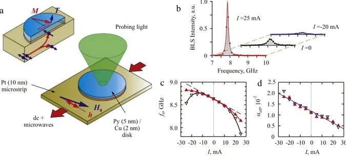
Fig. 1. Schematic of a simple SHE device. Inset illustrates the generation of pure spin current due to SHE in the Pt microstrip. (b) Representative FMR curves
recorded by BLS at different currents in the Pt microstrip, as labeled. (c) FMR frequency vs. current, measured in the continuous- (point-down triangles) and the pulsed-current (point-up triangles) regime. The dashed line is the calculated variation of the FMR frequency due to the Oersted field of the current. (d) The effective damping constant vs. current, determined in the continuous- (point-down triangles) and the pulsed-current (point-up triangles) regimes. The line is the linear fit to the data.
to control damping by SHE in metallic and insulating magnetic films has received significant attention [57–67]. The current-induced damping variations reported by different groups ranged from a few percent to complete compensation, in the latter case resulting in the onset of magnetic auto-oscillations [69,70].
In addition to the excitation of auto-oscillations, the ability to modify magnetic damping by SHE can be utilized for electronic tuning of the quality factor in microwave magnetic nano-resonators. This application requires not only efficient control of damping by the spin current, but also sufficiently small damping when no current is applied. Unfortunately, it is difficult to simultaneously satisfy both of these requirements in the SHE-based systems, since the same spin–orbit effects that produce spin currents also adversely affect the dynamic characteristics of the adjacent ferromagnet. As a result, the magnetic damping constant in thin ferromagnetic films in contact with SHE materials often increases by more than a factor of two [48,57].
An approach allowing one to simultaneously achieve large variations of the damping rate and minimize the increase of magnetic relaxation associated with the proximity of the SHE material was demonstrated in [59]. The test devices used in these studies consist of a 5 nm thick and 2
µ
m in diameter Ni80Fe20=
Permalloy (Py) disk fabricated on top of a 10 nmthick and 2
.
4µ
m wide Pt microstrip, as shown schematically inFig. 1(a). To reduce the adverse effects of strong spin–orbit coupling in Pt on the magnetization in Py [102], the Py disk is separated from the Pt microstrip by a 2 nm thick Cu spacer. The operation of the device is illustrated in the inset inFig. 1(a). Electrons with opposite directions of the magnetic moment are scattered toward the opposite boundaries of the Pt film, due to the spin Hall effect in Pt. As a result, pure spin current is injected through the Cu spacer into the Py film, producing a spin-transfer torque T on its magnetization M. Spin torque either reduces or enhances the effective magnetic damping in the Py disk, depending on the direction of the current relative to the magnetization. The latter is aligned with the saturating static magnetic field. Damping is characterized by measurements of the ferromagnetic resonance (FMR) curves. The FMR is excited by applying a small-amplitude microwave-frequency current in addition to the dc current, producing an rf magnetic field h oriented perpendicular to axis of the Pt strip. The efficiency of STT is optimized when the static magnetic field is transverse to the Pt strip. However, in this experiment the in-plane field is tilted by 10°with respect to this direction to enable the coupling of the dynamic field with the magnetization in Py. Both dc and microwave currents are either continuous, or applied in 100 ns-long pulses with a repetition period of 2µ
s to reduce Joule heating.The FMR is detected by the micro-focus Brillouin light scattering (BLS) spectroscopy technique [28,103,104]. The probing laser light generated by a single-frequency laser is focused by a 100x microscope objective lens into a diffraction-limited spot on the surface of the Py disk (Fig. 1(a)). The interaction of light with the magnetic excitations in Py results in its phase and/or amplitude modulation at the frequency of the excitations, which is analyzed by a six-pass Fabry–Perot interferometer. The resulting signal – the BLS intensity – is proportional to the intensity of the magnetic oscillations at the position of the probing spot.
Fig. 1(b) shows the FMR curves recorded by the BLS at different values of dc current I. The data were obtained by varying the frequency of the microwave signal from 7 to 10 GHz while simultaneously recording the BLS intensity at the same frequency. As seen fromFig. 1(b), at negative dc current the peak broadens and its amplitude is reduced, while at positive
current it becomes narrower and its amplitude is increased. By fitting the recorded spectra with the Lorentzian function, one can determine the FMR frequency f0and the spectral width∆f of the FMR peak. The dependence of f0on current is
shown inFig. 1(c). The results obtained with a continuous current are shown with open symbols, whereas pulsed-current results are shown with solid symbols. In both cases, the FMR frequency exhibits a significant dependence on current, due to the combined effects of Joule heating, STT, and the Oersted field HIproduced by the current. The latter can be calculated
based on the geometrical parameters of the Pt strip. The dashed line inFig. 1(c) shows the FMR frequency calculated using the Kittel formula [105]
f0
=
γ
H
(
H+
4π
M0),
(2)where
γ
is the gyromagnetic ratio, 4π
M0is the saturation magnetization, and H= |
H0+
HI|
. The experimental data exhibita linear variation at small I, closely following the calculated line. This indicates that the measured variations of f0at small
I are dominated by the Oersted field. At larger I, the measured dependences deviate from the calculation, which can be
attributed to the variations of the effective magnetization Mecaused by the combined effects of STT and Joule heating. The
contribution of Joule heating can be separated from that of STT by comparing the results obtained in the constant-current and the pulsed-current regimes. As seen from the data ofFig. 1(c), heating significantly affects the FMR frequency only at large currents.
Based on the measured values of f0and∆f , one can determine the current-dependent effective magnetization Me
(
I)
andthe effective Gilbert damping parameter
α
eff(
I)
of the Py disk. The value of Me(
I)
can be calculated using the Kittel formulaEq.(2). One can determine
α
eff(
I)
, from the expressionα
eff=
∆f
2
γ (
H+
2π
Me)
(3) derived from the Landau–Lifshitz–Gilbert (LLG) equation, taking into account the demagnetization effects for an in-plane magnetized film [106]. The results of calculations are shown inFig. 1(d). The value
α
eff=
0.
011 at I=
0 is close to thestandard value
α =
0.
008 for Permalloy, demonstrating that the effect of Pt on damping in Py is minimized by the insertion of the Cu spacer. The value ofα
effvaries by about a factor of 4 within the studied range of current, and the smallest achievedvalue
α
eff=
0.
004 is only half of the standard value for Permalloy, demonstrating that SHE can be utilized as an efficientand practical mechanism for controlling the dynamical characteristics of ferromagnets. Moreover, the obtained dependence
α
eff(
I)
[Fig. 3(b)] is the same for the continuous and the pulsed current, indicating that damping is not significantly affectedby Joule heating.
In addition to the FMR measurements, the variation of the effective damping due to SHE can be determined from the time-resolved measurements of the temporal decay of magnetization precession excited by pulsed current [65], or by analyzing the parametric instability threshold [107,108]. Both of these methods yield a linear dependence of the effective damping constant on current, consistent with the FMR measurement discussed above. We emphasize that a simple linear dependence is observed only at modest currents. More complex dynamical behaviors of the magnetic system are expected at spin currents approaching the point of complete damping compensation, due to the increasingly significant role of nonlinear phenomena. As will be discussed in the next section, these deviations are caused by the strong enhancement of magnetic fluctuations concurrent with the reduction of effective damping.
2.2. Enhancement and suppression of magnetic fluctuations
The effects of STT on magnetic fluctuations have been extensively investigated for traditional devices driven by the spin-polarized electric current. For example, studies of magnetization reversal in nano-elements showed that STT can modify their thermal activation rates, which was interpreted as evidence for the effect of STT on thermal fluctuations [109,110]. This effect was measured directly by noise spectroscopy in magnetic tunnel junctions, taking advantage of their large magnetoresistance [111–113]. However, such electronic measurements require a finite dc bias and are limited to magnetic configurations producing large magnetoresistive signals. In contrast to the typical multilayer STT devices that require nontransparent electrical contacts to the magnetic layers, the geometry of devices driven by pure spin current allows optical access to the active magnetic layer. Therefore, these systems can be studied by the BLS spectroscopy, which is uniquely suited for the detection of magnetic fluctuations due to its unmatched sensitivity. In particular, the BLS spectroscopy is capable of detecting magnetic fluctuations, always present at room temperature, even in the absence of electrical current.
The experiments described below [68] were performed with a sample similar to that shown inFig. 1(a), but without the Cu spacer between the Py and Pt films. Since these measurements do not require excitation of magnetization dynamics by the high-frequency magnetic field, only dc current was applied, and the static magnetic field H0was oriented perpendicular
to the Pt microstrip to maximize the efficiency of SHE. Magnetic fluctuations were detected by BLS, which yielded a signal proportional to the square of the dynamic magnetization, or equivalently to the energy associated with the magnetic fluctuations. In the FMR measurements, the quasi-uniform precession mode of the sample driven by the rf field dominates over all the other modes. In contrast, in the fluctuation spectroscopy measurements, all the magnetic modes are simultaneously excited due to the interactions between the spin system and the lattice. In thermal equilibrium, the intensities of the modes follow the Bose–Einstein statistics with zero chemical potential [114,115].
a
b
c
d
e
f
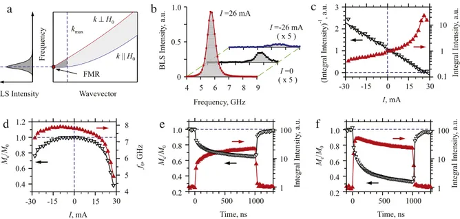
Fig. 2. (a) Schematic of the spin-wave spectrum for an in-plane magnetized ferromagnetic film (right), and a typical BLS spectrum of magnetic fluctuations
dominated by the contribution of long-wavelength spin-wave modes (left). The lightly shaded area is the spin-wave manifold, its part contributing to the BLS spectrum is shaded dark. (b) Representative BLS spectra of magnetic fluctuations in the SHE system recorded at different currents in the Pt microstrip, as labeled. (c) Normalized integral intensity under the BLS peak (point-up triangles) and its inverse (point-down triangles) vs. current. (d) The FMR frequency
f0(point-up triangles) and the effective magnetization normalized by its value at I=0 (point-down triangles) vs. current. (e) and (f) Temporal evolution
of the normalized effective magnetization (point-down triangles) and the integral BLS intensity (point-up triangles) at I=25 and 30 mA, respectively.
The spectrum of the spin-wave modes [116,117] is schematically shown in the right panel ofFig. 2(a). The two solid curves show the dispersions of the spin waves propagating perpendicular and parallel to the direction of the static magnetic field, as labeled. These curves are the boundaries of the continuous spin-wave manifold shown by the shaded area. At finite temperatures, all these modes contribute to the magnetization fluctuations. The BLS microscopy is capable of detecting spin-wave modes within a limited range of spin-wavevectors 0
−
kmax∼
105cm−1[103,104], and its sensitivity to a specific modecontinuously decreases with the increase of the mode wavevector. As a result, the BLS spectrum of magnetic fluctuations is typically shaped as an asymmetric peak with the maximum at the frequency f0 of the FMR (Fig. 2(a) left panel). The
amplitude of this peak characterizes the intensity of the long-wavelength magnetic modes, while the frequency f0can be
used to determine the effective static magnetization of the sample.
Fig. 2(b) shows representative spectra of magnetic fluctuations recorded at three different values of dc current applied to the Pt microstrip, I
= −
26 mA, 0, and 26 mA. The magnetic moments in the spin current are parallel to the magnetization at I<
0, and antiparallel to it at I>
0. The decrease of the fluctuation peak’s amplitude at I<
0 is consistent with the expected enhancement of the effective magnetic damping due to the SHE-induced STT, as discussed above. Similarly, the increase of the fluctuation peak amplitude at I>
0 is consistent with the expected decrease of the effective damping. However, the modification of damping cannot account for the dependence of the integral intensity of the BLS spectra on current, shown with point-up triangles inFig. 2(c). The integral intensity of the BLS peak is proportional to the average fluctuation energy of the long-wavelength magnetic modes. In the classical limit applicable to these modes, the equilibrium fluctuation energy associated with each dynamical mode is kBT , regardless of damping [118]. If the magnetic system wereto behave simply as if the damping were varied while maintaining thermal equilibrium, the integral intensity would remain constant. In contrast, at I
=
28 mA the integral intensity increases by more than a factor of 30 relative to the equilibrium value, while at I= −
28 mA it decreases by more than a factor of two. These results clearly demonstrate that in addition to modifying the damping, STT brings the magnetic system out of equilibrium. The observed behaviors are consistent with the established theories of STT, once different contributions to the dissipation and the associated fluctuating fields are separately considered [68,99]. The theory predicts a linear dependence of the inverse integral intensity on current, in agreement with the data shown inFig. 2(c) by the point-down triangles. One can extrapolate the small-current linear variations of the inverse intensity to determine the intercept IC=
28 mA, corresponding to the critical current at which the intensity of the BLS peakdiverges due to the complete damping compensation. At currents above IC, the system can be expected to enter the
auto-oscillation regime [99]. Instead, the integral intensity saturates and starts to decrease at I
>
26 mA (Fig. 2(c)), indicating an onset of a new relaxation process that limits the amplitude of magnetic fluctuations and prevents the onset of current-induced auto-oscillations.The central frequency f0of the peak exhibits a red shift at I
>
0 (point-up triangles inFig. 2(d)) that becomes particularlysignificant at large currents. It is caused by the decrease of the effective magnetization Me, due to the increased intensity of
a
b
c
d
e
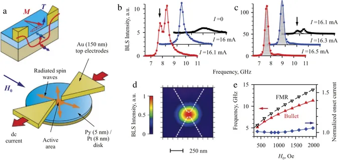
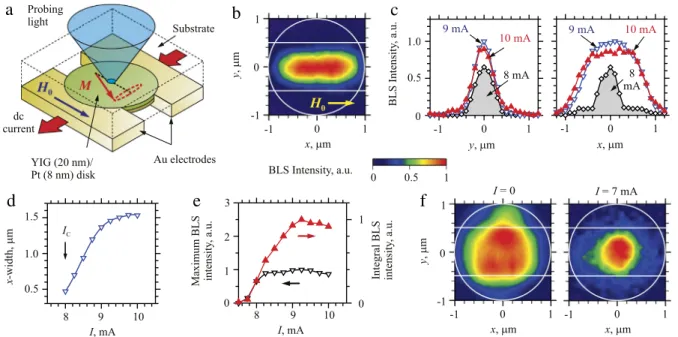
Fig. 3. (a) Schematic of the nano-gap spin-Hall nano-oscillators. The inset illustrates the local injection of the electric current and the generation of the
spin current inside the gap between the electrodes. (b) BLS spectra in the fluctuation enhancement regime. The arrow marks the new spectral peak that appears at the critical current. (c) BLS spectra of magnetization auto-oscillations. (d) Normalized color-coded spatial map of the auto-oscillation bullet mode. Dashed lines show the contours of the electrodes. (e) The FMR frequency in the Py film (point-down triangles), the auto-oscillation frequency at the onset current (point-up triangles), and the oscillation onset current normalized by its minimum value (diamonds) vs. static field.
once the Oersted field of the dc current is incorporated into the expression for the magnetic field H. We note that the linear variation of f0at small currents is perfectly described by the effect of Oersted field, confirming that the field-like torque is
negligible in this system.
The magnitude of Me (point-down triangles in Fig. 2(d)) monotonically decreases with increasing current even at
I
>
26 mA. Thus, the total intensity of magnetic fluctuations keeps increasing at large currents, even after the intensity of long-wavelength fluctuations saturates and starts to decrease. This can be explained by the different behaviors of different spin wave modes. The BLS spectra are selectively sensitive to the long-wavelength fluctuations, while the total fluctuation intensity is dominated by the much larger phase volume of short-wavelength modes. Thus, as the current approaches the critical value, only the long-wavelength fluctuations become suppressed resulting in the saturation of the BLS intensity. Meanwhile, the short-wavelength fluctuations continue to increase resulting in decreasing Me.Additional information about the mechanisms contributing to the phenomena observed at large currents was obtained from time-resolved BLS measurements, performed with dc current applied in 1
µ
s long pulses.Fig. 2(e) shows the temporal evolution of the integral BLS peak intensity (point-up triangles) and of the effective magnetization Me(point-down triangles)obtained at a current I
=
25 mA below the onset of saturation of the fluctuation intensity.Fig. 2(f) shows the results of the same measurements for I=
30 mA, above the onset of saturation. In both cases, the value of Merapidly changesat the onset of the pulse, and subsequently varies on a much longer characteristic timescale. At the end of the pulse, Me
first rapidly increases, and then slowly relaxes. These results allow one to separate the contribution of STT from the Joule heating. The rapid increase of Meat the end of the pulse can be attributed to the relaxation of the magnetic system toward
equilibrium with the lattice. This process is characterized by the spin-lattice relaxation rate of a few nanoseconds. The subsequent slow relaxation of Meis associated with the simultaneous cooling of the lattice and of the magnetic system.
Therefore, by comparing the magnitudes of the fast and the slow variations of Meat the end of the pulse, one can estimate
that the relative contribution of Joule heating to the total enhancement of fluctuations does not exceed 30%.
While the temporal evolution of Meis similar at I
=
25 mA (Fig. 2(d)) and at I=
30 mA (Fig. 2(e)), the evolution ofthe BLS intensity is qualitatively different in these two cases. At I
=
25 mA, the intensity abruptly jumps at the onset of the pulse, and subsequently continues to slowly increase. At I=
30 mA, the intensity also initially abruptly increases, but then slowly decreases over the rest of the pulse duration. These different temporal behaviors likely originate from the same nonlinear dynamical mechanisms that lead to the saturation of intensity in the static measurements (Fig. 2(c)). Since the initial increase of intensity at I=
30 mA is significantly larger than at I=
25 mA, it is the subsequent slow variation that results in the saturation seen in the static measurements. By examining the temporal evolution of Meand ofthe intensity, one can infer that the fluctuations of both the long- and the short-wavelength modes are initially enhanced more significantly at I
=
30 mA than at I=
25 mA. This enhancement leads to nonlinear coupling among different modes, resulting in the redistribution of the fluctuation energy within the spin-wave spectrum. Such nonlinear mode coupling can be generally expected to drive the magnetic subsystem toward a thermalized distribution [119,120]. Sincethe long-wavelength fluctuations are most significantly enhanced by STT due to their lower damping, they can be also expected to be most significantly suppressed by the nonlinear scattering, preventing the onset of auto-oscillation. As the fluctuation starts to diverge when the critical current is approached, the nonlinear scattering processes that suppress long-wavelength fluctuations become increasingly efficient. Consequently, complete compensation of the magnetic damping by SHE cannot be achieved in the discussed system because of the additional damping that emerges at large currents due to the nonlinear scattering processes. While the detailed mechanisms of these processes are still unclear, one can expect that in a strongly nonequilibrium spin system characterized by the reduction of the effective magnetization by more than a factor of two (Fig. 2(d)), nonlinear interactions can be mediated not only by the resonant three- and four-magnon scattering processes [106,121], but can also include complex non-resonant processes that do not require exact phase synchronism of the interacting modes (see, e.g., [122–124]).
The results discussed above clearly demonstrate that one of the main difficulties in the implementation of magnetic auto-oscillators driven by pure spin current is associated with the non-selective effect of STT. The spin torque simultaneously enhances all the dynamic magnetic modes, resulting in the onset of nonlinear interactions that limit the intensity of the fundamental quasi-uniform precession mode. In the next section, we will discuss an approach allowing one to overcome this difficulty and achieve magnetization auto-oscillations in SHE systems.
3. Spin Hall-effect magnetic nano-oscillators based on metallic ferromagnets
One of the main benefits of spintronic and magnonic devices based on pure spin currents is their compatibility with low-loss magnetic insulators. However, the first demonstrations of coherent magnetization auto-oscillations driven by SHE were reported for all-metallic spin-current systems [69,70]. Extensive subsequent studies of these systems have produced novel device geometries and significant improvement of the oscillation characteristics [71–78,90–93]. In contrast, the insulator-based devices, which will be discussed in detail in Section4, are only starting to emerge. Their performance is still significantly lagging behind the all-metallic spin-current oscillators.
3.1. Self-localized bullet oscillation mode in spin-Hall systems
As discussed in the previous section, damping reduction by SHE can be relatively easily achieved at small current densities. However, complete compensation of damping by the spin current, which is necessary to achieve steady-state magnetization auto-oscillations, is not a straightforward extension of the damping reduction. The simultaneous enhance-ment of many dynamical modes by spin current results in nonlinear damping enhanceenhance-ment, preventing the transition to the auto-oscillation regime. Therefore, it is necessary to suppress nonlinear interactions to achieve auto-oscillation. Since magnon–magnon scattering rates are proportional to the populations of the corresponding modes, the detrimental effects of nonlinear damping can be avoided by selectively suppressing all the modes, except for the ones that can be expected to auto-oscillate. To achieve such a selectivity, one can take advantage of the frequency-dependent damping caused by the spin-wave radiation in a system based on the local injection of spin current into an extended magnetic film [69].
The schematic of the device implementing mode-selective radiation losses is shown inFig. 3(a). The device is formed by a bilayer of a 8 nm thick film of Pt and a 5 nm thick film of Permalloy patterned into a disk with the diameter of 4
µ
m. Two 150 nm thick Au electrodes with sharp points separated by a 100 nm wide gap are placed on top of the bilayer, forming an in-plane point contact. The sheet resistance of the bilayer is nearly two orders of magnitude larger than that of the Au electrodes. As a consequence, the electrical current induced in the bilayer by the voltage between the electrodes is localized predominantly within the nano-gap region. The electric current produces a pure spin current due to the spin Hall effect in Pt. The spin current is injected into the Py film in a relatively small active area defined by the geometry of the electrodes (see the inset inFig. 3(a)). In this area, the local spin current enhances a large number of different dynamical modes. The high-frequency spin-waves are characterized by large group velocities (see the spin-wave spectrum inFig. 2(a)). Consequently, they quickly escape from the active region, resulting in their efficient suppression by the radiation losses. Meanwhile, the low-frequency modes with large wavelengths have a much smaller group velocity, and therefore their radiation losses are minimal. Moreover, as will be discussed below, this damping imbalance is further enhanced by the formation of a self-localized ‘‘bullet’’ mode [125], which is completely free from the radiation losses.Fig. 3(b) and (c) show the BLS spectra obtained with the probing laser spot positioned in the center of the nano-gap, at different values of the dc current I. At I
=
0 (Fig. 3(b)), the BLS spectrum exhibits a broad peak produced by incoherent magnetization fluctuations in the Py film. Just like in the systems driven by spatially uniform spin currents (see Section2.2), this peak grows with increasing current due to the enhancement of fluctuations by SHE. Additionally, its rising slope becomes increasingly sharper than the trailing slope, consistent with the selective preferential enhancement of the low-frequency modes. In contrast to the systems driven by spatially uniform spin currents, the integral BLS intensity does not saturate when the current approaches the critical value IC≈
16.
1 mA. Instead, a new peak appears in the BLS spectrum at ICat afrequency below the fluctuation peak, as indicated inFig. 3(b) by an arrow. The intensity of this peak rapidly grows with increasing current, and then saturates at a value that exceeds the intensity of thermal fluctuations by more than two orders of magnitude (Fig. 3(c)). These behaviors clearly indicate an onset of the auto-oscillations, and show that the radiation-loss mode-selection mechanism allows one to overcome the nonlinear effects that prevent auto-oscillation in systems with
spatially extended spin current injection. Moreover, by comparing the spectra obtained at I
=
16.
1 mA and at 16.3 mA, one can infer that the onset of auto-oscillations is accompanied by a decrease in the intensity of the fluctuation peak, suggesting that the energy of spin current is mainly channeled into the auto-oscillation mode.Since the peak corresponding to the auto-oscillation mode is not present in the thermal fluctuation spectrum, one can conclude that it represents a new mode that does not belong to the linear spectrum of spin waves. Since energy can be radiated only by propagating spin waves and there are no available spin-wave spectral states at the auto-oscillation frequency, the auto-oscillation mode must be completely free from the radiation losses. The nature of this new mode can be elucidated by spatial mapping of the dynamic magnetization at the frequency of auto-oscillations, which can be implemented by rastering the probing laser spot in the two lateral directions and simultaneously recording the BLS intensity. An example of the obtained maps is presented inFig. 3(d). These data show that the auto-oscillations are localized in a very small area in the gap between the electrodes. The measured spatial distribution is a convolution of the actual spatial profile with the instrumental function determined by the shape of the laser spot. Taking into account the size of the spot of about 250 nm, one can estimate from the measured distribution that the size of the auto-oscillation region is less than 100 nm, significantly smaller than the characteristic size of the current localization region. This indicates that the auto-oscillation area is determined not by the spatial localization of the spin current, but by the nonlinear dynamical properties of the magnetic system. Such nonlinear self-localization resulting in the formation of a standing spin-wave soliton (or spin-wave bullet) has been predicted for extended magnetic films subjected to local spin current injection [125]. This conclusion is further supported by the results of numerical micromagnetic simulations [126,127], which reveal that a self-localized bullet with typical dimensions of about 80 nm is formed in the studied system.
The planar nano-gap oscillator is robust with respect to the experimental parameter variations.Fig. 3(e) shows the static-field dependences of its oscillation characteristics. As seen from these data, the devices exhibit auto-oscillations for all static fields in the interval from 400 to 2000 Oe, and their oscillation frequency can be efficiently tuned by the field within a broad range. The auto-oscillation frequency (point-up triangles inFig. 3(e)) always remains below the FMR frequency (point-down triangles) in the Py film, as expected for the nonlinear self-localized bullet mode. The oscillation onset current (diamonds) exhibits a modest variation of about 5% within the entire field range.
Because of the limited spectral resolution of the BLS spectroscopy, the measured BLS spectra (Fig. 3(c)) cannot provide accurate information about the spectral width of the auto-oscillation peak, which is an important parameter characterizing the coherence of the spin-current induced oscillations. Measurements of the oscillation linewidth of the nano-gap oscillators were performed by electronic microwave spectroscopy in [71]. In particular, it was shown that these devices produce a relatively large microwave power and exhibit a small auto-oscillation linewidth at cryogenic temperatures. However, both of these characteristics significantly degrade as the temperature is increased. This result is not surprising, since the small size of the self-localized bullet mode leads to the small total oscillation energy comparable to the energy of thermal fluctuations at room temperature. As a result, the coherence of the auto-oscillations is strongly affected by the thermal noise. In principle, these effects can be avoided by modifying the geometry of the oscillator. For example, a moderate improvement of the spectral characteristics of planar point-contact oscillators was achieved by patterning of the Pt layer into a 400 nm diameter disk centered in the active device region [74]. This improvement was likely caused by the more efficient radiation of spin waves from the active device region, since the area of Py interfaced with Pt, which is detrimental to the magnetization dynamics, was reduced in these devices. Overall, the possibility to control the auto-oscillation characteristics by modifying the device geometry is limited, since local injection of spin current into a continuous magnetic film leads to the spontaneous formation of the bullet mode, whose spatial dimensions are determined by the nonlinear self-localization effects rather than by the spin-current injection area.
3.2. Effects of confining effective potential in spin-Hall oscillators
Spin-Hall nano-oscillators capable of efficient room-temperature generation of coherent microwave signals were demonstrated in [75]. The improvement was achieved by controlling the auto-oscillation characteristics via magnetic dipolar effects instead of the self-localization. Specifically, the localized auto-oscillation mode was formed due to the confinement in an effective potential well produced by the non-uniformity of the internal static magnetic field in a bow tie-shaped magnetic nanoconstriction. The devices based on this principle are characterized by a large oscillation area, minimizing the effects of thermal fluctuations and resulting in a narrow room-temperature spectral linewidth without compromising the single-mode regime of auto-oscillation.
A schematic of these devices is shown inFig. 4(a). They are fabricated from a 4
µ
m wide Py(5 nm)Pt(8 nm) bilayer strip. A sharp bow tie-shaped nanoconstriction with the width of 150 nm, radius of curvature of about 50 nm, and an opening angle of 22°is defined in the center of this strip. The principle of the device operation is very similar to the nano-gap oscillators discussed in Section3.1. The electrical current flowing in the Pt layer induces a spin current due to SHE, which is injected into Py. The abrupt narrowing of the current-carrying Pt layer in the nanoconstriction results in a strong increase of the local current density, which exhibits a sharp peak with the width of about 0.
3µ
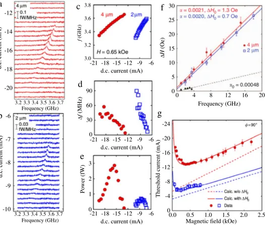
m along the device axis (see the calculated current distribution in the inset inFig. 4(a)). Since the spin current injected into Py is proportional to the current density in Pt, this region of large current density also defines the active device area, in which the injected spin current is sufficiently large to cause a sizable effect on the magnetization. Note that the active region is surrounded by the magnetic film that supportsFig. 4. (a) Schematic of the nanoconstriction spin-Hall oscillator. Inset shows the calculated electric current distribution in the Pt layer. (b) Representative
auto-oscillation spectrum measured by electronic microwave spectroscopy at I=3.75 mA. (c) Integral microwave power (point-down triangles and right
scale) and spectral linewidth of the auto-oscillation signal (point-up triangles and left scale) vs. current. (d) Spectra of magnetization oscillations recorded by BLS at the labeled values of current. (e) Spatial map of the dynamic magnetization recorded by BLS in the auto-oscillation regime (left), and the calculated spatial distribution of the demagnetizing field in the plane of the Py layer (right).
propagating spin waves, similarly to the nano-gap devices. Consequently, the mode-dependent radiation-loss mechanism that suppresses the nonlinear mode coupling phenomena is also effective in the nanoconstriction devices.
The symmetry of SHE implies that the largest effect of spin current is achieved when the magnetization is oriented perpendicular to the direction of the electric current flow. However, if the applied static field H0is exactly perpendicular to
the direction of the current, the current-induced oscillations cannot generate electronic signals at the oscillation frequency via the anisotropic magnetoresistance (AMR) mechanism. Therefore, to enable electronic detection of auto-oscillations, in the experiments described below the field was applied in-plane at an angle
α =
60°relative to the current (Fig. 4(a)).Fig. 4(b) and (c) show the results of device characterization by the electronic microwave spectroscopy. A dc current
I was applied to the nanoconstriction through the low-frequency branch of a microwave bias tee. The resulting
current-induced magnetization oscillations were converted by the AMR effect into a microwave voltage, which was detected by a spectrum analyzer. A narrow spectral peak appeared in the microwave spectra at I
>
IC≈
3.
3 mA (Fig. 4(b)). The intensityof the detected peak gradually increases with increasing current while its spectral linewidth decreases (Fig. 4(c)), reaching a minimum of 6.2 MHz at I
=
3.
75 mA. The integral intensity of the microwave signal reaches a maximum of about 7 pW at I=
3.
95 mA. The power generated by this device is comparable to that delivered by the giant-magnetoresistance spin-torque oscillators operating at comparable frequencies (see, e.g., [14] and references therein), despite the relatively low magnitude of the AMR effect. At I>
3.
95 mA, the generation power abruptly decreases, while the auto-oscillation peak broadens and splits into multiple peaks, marking a transition to the multimode auto-oscillation regime.The large generated microwave power can be attributed to the large oscillation amplitude of the nanoconstriction region that provides a dominant contribution to the device resistance, while the small generated linewidth is likely associated with the large volume of the oscillating magnetization, making the oscillator insensitive to thermal fluctuations. This hypothesis was confirmed by micro-focus BLS measurements.Fig. 4(d) shows the BLS spectra of the magnetization oscillations recorded at different currents. The BLS spectrum acquired at I
=
0 reflects the thermal magnetization fluctuations. At small I (1 and 3 mA inFig. 4(d)), the fluctuations are enhanced and a peak appears on the low-frequency shoulder of the thermal fluctuation background. This peak rapidly increases in intensity at I>
IC(3.8 mA inFig. 4(d)), marking the onset of current-inducedmagnetization auto-oscillations. Note that the spectral peak corresponding to the auto-oscillation mode does not abruptly appear at the onset current, as was the case for the nano-gap oscillators, but instead gradually emerges at I
<
IC. Thisbehavior can be contrasted with the spin-wave bullet observed in the nano-gap oscillator, which formed spontaneously at the oscillation onset due to the nonlinearity associated with the large amplitude of auto-oscillation. Further evidence against the formation of the ‘‘bullet’’ mode in the nanoconstriction devices is provided by the smooth variation of the center frequency of the observed spectral peak (dashed line inFig. 4(d)). In contrast, the formation of the bullet mode is expected to be accompanied by a frequency jump.
Spatially resolved BLS measurements (left panel inFig. 4(e)) further elucidated the nature of the oscillation mode. As seen fromFig. 4(e), the oscillation mode is localized in the nano-constriction area, and exhibits an elliptical shape elongated in the direction perpendicular to the external field H0. Taking into account the finite size of the probing laser spot, one can
estimate from the BLS data that the spatial dimensions of the localization area are 0
.
25µ
m in the direction parallel to H0,and 0
.
4µ
m perpendicular to it. These values are significantly larger than the typical spatial dimensions of about 80 nm expected for the bullet mode (Section3.1). The nature of the auto-oscillation mode was clarified by the micromagnetic simulations of the static magnetic state of the nanoconstriction. The right panel inFig. 4(e) shows the spatial distribution of the demagnetizing field in the area of the nanoconstriction, calculated using the OOMMF micromagnetic simulation software [128]. The calculations show that the edges of the nanoconstriction produce a strong demagnetizing field that opposes the external static magnetic field, resulting in a local decrease of the internal field in Py in the nanoconstriction area. The local reduction of the static internal field creates an effective potential well for spin waves [129,130] resulting in the formation of a localized dynamic mode. This mechanism is similar to the well-known effect of quantum state localization of particles in potential wells. In contrast to all the other dynamical modes of the system, the localized mode is free from radiation losses. Consequently, it is preferentially enhanced by the spin current, resulting in single-mode auto-oscillations. This auto-oscillation mechanism is qualitatively different from that in the nano-gap oscillators, where only propagating linear modes exist in the linear regime at small currents, and the localized bullet mode is spontaneously formed only at the onset of auto-oscillation due to the nonlinear self-localization effects.While the operational characteristics of SHE oscillators can be significantly improved by increasing the spatial size of the auto-oscillation mode using the dipolar-field localization mechanism, this increase inevitably leads to a multimode auto-oscillation regime observed in nanoconstriction devices at large currents (Fig. 4(c)). The oscillation characteristics significantly degrade in this regime, likely due to thermal mode hopping. Therefore, this regime is not beneficial for technical applications of the SHE oscillators. Note that further increase in the spatial size of the auto-oscillation area up to 2
µ
m, which was implemented in the nano-wire spin-Hall oscillators [76], does not result in improvement of the oscillation characteristics. Instead, single-mode auto-oscillations are observed only in a very narrow range of parameters. It was recently shown that the single-mode oscillation regime is more robust in a tapered nanowire [78]. This improvement is mostly caused by the reduction of the auto-oscillation area due to the non-uniform distribution of the current density along the tapered nanowire. The limiting case of the tapered-nanowire geometry is the nanoconstriction oscillator discussed above.Since the increase in the dimensions of the auto-oscillation region does not allow an improvement in the microwave power generated by the SHE devices, the most straightforward route to achieve such an improvement is associated with the implementation of arrays of mutually synchronized oscillators, as was previously suggested for traditional STT devices [22,131–134].
3.3. Synchronization of spin-Hall oscillators
One of the distinguishing characteristics of STT-driven magnetic nano-oscillators is a strong nonlinearity that enables their efficient synchronization to external periodic signals over a wide frequency range, as well as mutual synchronization of oscillators with significantly different frequencies [99]. This feature may allow the development of microwave sources with improved generation coherence using mutually synchronized oscillator arrays. The implementation of such arrays with spin-Hall oscillators is significantly more straightforward than with the conventional ones due to their simpler planar geometry.
The ability of SHE-based oscillators to synchronize to external signals was first demonstrated in [72]. In this work, the characteristics of synchronization were studied for nano-gap devices discussed in detail in Section3.1. To study the effects of external signals on the oscillation characteristics, a microwave current was applied simultaneously with the dc current
I. The microwave current induced a dynamic Oersted magnetic field in the Py film. The operation of spin-Hall oscillators is
optimized when the static magnetic field is perpendicular to the current flow, such that the dynamic field created by the microwave current is parallel to the static magnetization. In this geometry, the dynamic magnetic field can only couple to the dynamic magnetization through the parametric process that becomes efficient when the driving frequency is close to twice the auto-oscillation frequency [106]. Under these conditions, the oscillators were found to exhibit efficient parametric synchronization characterized by a relatively wide synchronization frequency interval controlled by the magnitude of the microwave signal and by the dc current flowing through the device. In contrast to the conventional STT oscillators, the synchronization of spin-Hall oscillators occurred only above a certain threshold microwave signal power, which was attributed to the influence of magnetic fluctuations enhanced by the spin current, whose importance was discussed in Section2.2.
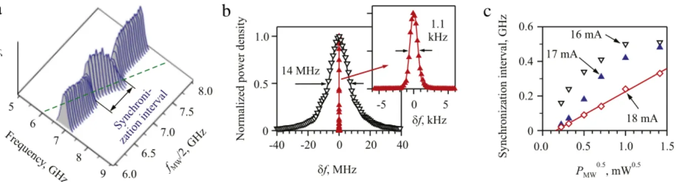
Fig. 5(a) shows the BLS spectra recorded at I
=
16.
5 mA, in the stable auto-oscillation regime of the nano-gap device with a saturated intensity (see alsoFig. 3(c)). The data were recorded with the frequency fMW of the microwave signalvarying from 12 to 16 GHz and the power fixed at P
=
0.
5 mW. The spectra exhibit a narrow intense auto-oscillation peak, regardless of the external microwave frequency. When fMW/
2 approaches the auto-oscillation frequency, the latter startsto exactly follow fMW
/
2 (dashed line inFig. 5(a)), as expected for the parametrically synchronized oscillation. In additionto the frequency locking demonstrated by the BLS measurements, the reduction of the auto-oscillation linewidth in the synchronized regime was analyzed by the electronic spectroscopy. These measurements demonstrated that at cryogenic temperatures the linewidth of the auto-oscillation in the synchronized regime is reduced by up to four orders of magnitude (Fig. 5(b)).
a
b
c
Fig. 5. (a) BLS spectra of spin-current induced magnetic auto-oscillations in the presence of an additional microwave signal, whose frequency fMWis varied from 12 to 16 GHz. (b) Electronically measured spectrum of the free-running auto-oscillations in the absence of an external microwave signal (point-down
triangles), and the spectrum of auto-oscillations synchronized with an external microwave signal (point-up triangles). The frequencyδf is measured relative
to the peak center, which coincides with fMW/2 in the synchronized regime. (c) Synchronization interval vs. the amplitude of the dynamic magnetic field
of the microwave current measured in the units of the square root of driving microwave power, at the labeled values of dc current.
Fig. 5(c) shows the dependence of the synchronization interval∆fS(seeFig. 5(a)) on the dynamic microwave magnetic
field, which is proportional to the square root of the driving microwave power P. No synchronization was observed at microwave powers below PS
th
≈
0.
03 mW, regardless of the dc current value. At a current I=
18 mA significantly abovethe oscillation onset,∆fSexhibits an approximately linear dependence on P1/2above the threshold PthS (diamonds and solid
straight line inFig. 5(c)), while at smaller currents close to the oscillation onset, a rapid increase of∆fSat small microwave
power is followed by saturation (triangles inFig. 5(c)). Note that the observed behaviors cannot be described by the theory of synchronization of nonlinear single-mode oscillators [99], which predicts a universal linear dependence of∆fSon P1/2. This
theory also predicts synchronization at arbitrarily small driving microwave power, since the synchronization is known to be a non-threshold phenomenon. Theoretical analysis performed in [72] showed that this inconsistency can be explained by the effects of the magnetic fluctuations enhanced by the spin current. In particular, by including the effects of fluctuations in the auto-oscillator model, the non-zero power threshold of the synchronization process was obtained. The effective amplitude of fluctuations, estimated by comparing the theoretical and the experimental results, is about two orders of magnitude larger than its thermal-equilibrium magnitude at room temperature. This result is consistent with the expected influence of spin current, which brings the magnetic system into a strongly non-equilibrium state (Section2.2). Moreover, it was found that the synchronization threshold was not reduced even at cryogenic temperatures, indicating that the magnetic noise that determines the threshold is dominated not by the thermal fluctuations of the lattice, but rather by the magnetic modes enhanced by the spin current.
The results discussed above demonstrate the ability of SHE-driven oscillators to synchronize to external signals, which is a necessary, although not sufficient, condition for the ability to mutually synchronize several oscillators. Note that the layout of the nanoconstriction spin-Hall oscillators is uniquely suited for the studies of mutual synchronization. Indeed, it enables easy implementation of the oscillator chains, by using a Py/Pt strip with a periodic series of nanoconstrictions. The individual oscillators in the chain can phase-lock to each other due to the exchange interaction, if their oscillation areas slightly overlap. Because of the relatively large oscillation area, such overlap can be easily achieved by placing the neighboring nanoconstrictions at a distance of 200–300 nm from each other. This separation allows a sufficiently large modulation of the driving current density along the device axis, resulting in well-defined separate effective potential wells defining the neighboring oscillators. An additional advantage provided by this layout is that the current required for the oscillations in a chain is independent of the number of oscillators. The possibility of mutual synchronization in chains of nanoconstriction devices was demonstrated by numerical simulations [135] and was recently experimentally confirmed [80].
4. Spin Hall-effect magnetic nano-oscillators based on magnetic insulators
We now turn our attention to the study of injecting pure spin current into magnetic insulators. The microscopic mecha-nisms of transfer of angular momentum between a normal metal and a ferromagnetic layer are now quite different. While in the previous case of a metallic ferromagnet, electrons in each layer have the possibility to penetrate the other one, for magnetic insulators the transfer takes place exactly and solely at the interface. As mentioned in the introduction, insulating ferromagnets (garnets, ferrites) benefit from a much lower damping parameter than metals. This is because the disappear-ance of the electronic density at the Fermi level permits to get rid of a potent relaxation mechanism: the electron–magnon scattering [136].
Among different magnetic insulators, the material which has the lowest known damping is Yttrium Iron Garnet (Y3Fe5O12, YIG) [137]. Quite importantly YIG can be synthesized in large volume in the form of a single crystal with almost
no atomic disorder (FMR linewidths in polycrystals are usually much larger than those in single crystals). The smallest linewidths have been measured on polished YIG spheres of millimeter size. Three principal magnetic relaxation channels have been identified in these YIG spheres [137,138]. The potentially strongest one is linked to the exchange interaction. YIG
dP/dH (a.u.) 10 5 0 -5 -10 1270 1275 1280 1285 1290 H (Oe) 0 10 20 30 40 Frequency (GHz) Δ H p-p (Oe) 6 4 2 0
a
b
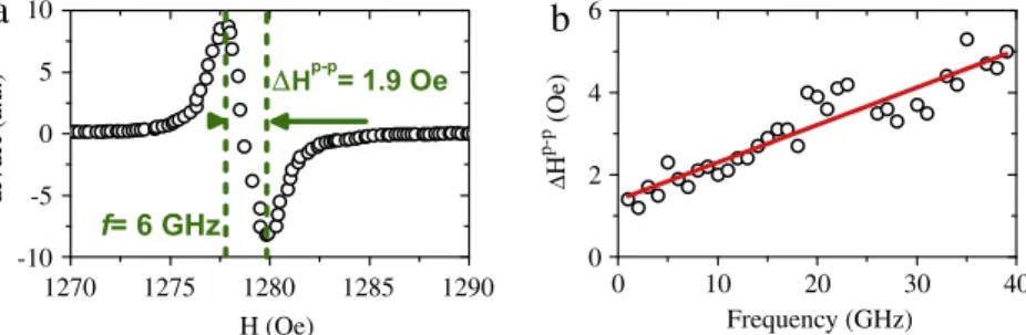
Fig. 6. Measurement of the magnons’ damping in 20 nm thick YIG films grown by pulsed laser deposition. (a) Derivative of the in-plane FMR absorption
peak measured at 6 GHz. (b) Frequency dependence of FMR absorption linewidth: the continuous line is a linear fit corresponding to a Gilbert damping
coefficient of 2×10⁻⁴[140].
is a ferrimagnet, which has a compensated magnetic moment on the Fe2+and Fe3+sites, both coupled by super-exchange. The associated relaxation process (the valence exchange relaxation) involves a charge transfer between the two ions, which can be activated by impurities. This effect is minimized when the YIG crystal is grown from ultra-pure material composition. At liquid nitrogen temperature, trace amount of impurities would normally dominate the relaxation. It appears in the form of an enhancement of the damping in a narrow temperature window, where the fluctuation rate of the charge transfer matches the Larmor frequency. The second potential relaxation channel is linked to the dipolar interaction. The associated relaxation process is the two-magnon decay of the uniform mode into degenerate modes due to pit scattering at the sample surface. This effect is minimized by polishing the sphere to perfection. For sample size of the order of the magnon propagation length, this broadening is inversely proportional to the sphere diameter. The third potential relaxation channel is due to spin–orbit coupling, which also sets the magnetic anisotropy. In the case of YIG this coupling is relatively small. It leads to a magnon–phonon coupling described by Kasuya and Le Craw [139], which can become the dominant relaxation channel at room temperature. This last contribution determines the ultimate linewidth of YIG. The resulting broadening at the center of the X-band (10 GHz) is about 0.25 Oe (or 0.7 MHz) at room temperature (corresponding to
α =
3×
10−5), and possibly0.01 Oe at liquid Helium temperature.
The situation, however, is very different for YIG thin films. These films are usually grown on Gadolinium Gallium Garnet, Gd3Ga5O12(GGG) substrate, which provides the necessary lattice matching to achieve epitaxial growth.Fig. 6(a) shows the
FMR spectrum measured at 6 GHz for a 20 nm thick YIG thin film grown by pulsed laser deposition (PLD) [140]. The 1.9 Oe separation between the two extrema of the derivative of the FMR absorption peak corresponds to the linewidth of 3.3 Oe. This linewidth is determined by a homogeneous and an inhomogeneous contributions, which can be separated by studying its frequency dependence. The Gilbert damping coefficient is extracted from the slope of a linear fit (see solid lineFig. 6(b)), and is found to be about
α =
2×
10−4. The finite ordinate intercept,∆H0=
2.
4 Oe, represents the inhomogeneouspart of the linewidth. Still the homogeneous part of the linewidth (1.6 Oe at 10 GHz) is almost an order of magnitude larger than the one reported previously for an isolated YIG sphere. The dominant relaxation channel in this case is the dipole–dipole interaction with the paramagnetic substrate [141]. Although the spin susceptibility of the GGG is reduced at room temperature and the FMR mode probed inFig. 6(a)–(b) is significantly shifted from the paramagnetic resonance of the GGG substrate, the remaining fluctuations are still sufficient to completely dominate all the other relaxation channels. This effect only gets worse at liquid nitrogen or liquid Helium temperature because the paramagnetic spin susceptibility of the substrate increases inversely proportional to the temperature.
The damping coefficient can also be inferred from the magnon decay length measured by propagating spin-wave spectroscopy [142] or the micro-focus BLS technique [85,143,144]. In the former case, two coplanar waveguides with different separation between them are patterned on top of the 20 nm thick YIG. The signal attenuation between the two antennas is then measured by a vector network analyzer. The characteristic propagation length of magnons depends strongly on their wave-vector. One observes that the characteristic propagation length of the longest wave-vector magnons lies in the range of few hundreds of micrometers [142].
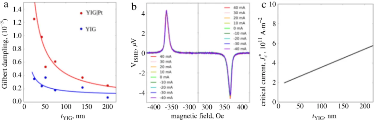
High quality level of YIG ultra thin films can also now be achieved by using liquid phase epitaxy (LPE), the reference method to grow micrometer thick YIG [145]. Recently, this growth method has allowed to obtain variable thickness YIG films from 200 nm down to 20 nm. The measured values of the Gilbert damping coefficient of these films are shown by the blue symbols inFig. 7(a). For the lowest LPE YIG thickness (20 nm), a linear fit of the frequency dependence of the linewidth yields
α =
4×
10−4and∆H0
=
1 Oe. When a few nanometers (7 nm) thick Pt layer is added on top of these YIG films,one observes an additional increase of the FMR linewidth [102], which varies inversely proportional to the YIG thickness (see red dotsFig. 7(a)). This indicates that a new relaxation channel has been opened up where angular momentum can escape through the interface and get absorbed in the metal through the so-called spin pumping effect [146]. Note that even for YIG, whose natural linewidth is only a few Oersted at 10 GHz, the additional broadening produced by the Pt is hardly observable if the thickness of the magnetic film, tYIG, exceeds a few hundreds of nanometers. By itself, the enhancement
of the damping reported inFig. 7(a) is an unambiguous evidence that spin current is transmitted at the interface between YIG and Pt. Furthermore, the hyperbolic dependence highlighted by the dashed curve is the proof that this new relaxation