HAL Id: hal-01983257
https://hal.archives-ouvertes.fr/hal-01983257
Submitted on 26 Nov 2020HAL is a multi-disciplinary open access archive for the deposit and dissemination of sci-entific research documents, whether they are pub-lished or not. The documents may come from teaching and research institutions in France or
L’archive ouverte pluridisciplinaire HAL, est destinée au dépôt et à la diffusion de documents scientifiques de niveau recherche, publiés ou non, émanant des établissements d’enseignement et de recherche français ou étrangers, des laboratoires
1+/N+ method: numerical simulation studies and
experimental measurements on the SPIRAL1 ECR
Charge Breeder
Arun Annaluru, Pierre Delahaye, Mickael Dubois, Pascal Jardin, Omar
Kamalou, Laurent Maunoury, Alain Savalle, Ville Toivanen, Emil Traykov,
Predrag Ujic
To cite this version:
Arun Annaluru, Pierre Delahaye, Mickael Dubois, Pascal Jardin, Omar Kamalou, et al.. 1+/N+ method: numerical simulation studies and experimental measurements on the SPIRAL1 ECR Charge Breeder. 23rd International Workshop on ECR Ion Sources, Sep 2018, Catania, Italy. pp.C01002, �10.1088/1748-0221/14/01/C01002�. �hal-01983257�
1+ / N+ method: numerical simulation studies and
experimental measurements on the SPIRAL1 ECR
Charge Breeder
A. Annaluru*,a, P. Delahayea, M. Duboisa, P. Jardina, O. Kamaloua, L. Maunourya, A. Savallea, V. Toivanena, P. Ujica and E. Traykovb
aGrand Accélérateur National d'Ions Lourds (GANIL),
Boulevard Henri Becquerel, 14000 Caen, France
bInstitut pluridisciplinaire Hubert Curien (IPHC),
23 Rue du Loess, 67200 Strasbourg, France E-mail: arun.annaluru@ganil.fr
ABSTRACT: In the framework of the SPIRAL1 facility, the R & D of charge breeding technique is of primary interest for optimizing the yields of radioactive ion beams (RIBs). This technique involves the transformation of mono-charged ion beams into multi-charged ion beams by operating an Electron Cyclotron Resonance (ECR) charge breeder (CB). During the SPIRAL1 commissioning, experimental studies have been performed in order to understand the transport of the beam through the CB with and without ECR plasma. Numerical simulations including ion optics and some ECR plasma features have been developed to evaluate ion losses during the ion transport through the CB with and without a simplified model of the ECR plasma.
KEYWORDS: Beam Optics; ECR Ion Sources; Accelerator modeling and simulations.
__________________________ * Corresponding author.
Contents
1. Introduction 1
2. Experimental activities with SPIRAL1 ECR Charge Breeder 2
2.1 Modification of axial magnetic field 2 2.2 Transmission efficiencies of 39K+ and 23Na+ 3
2.3 Charge breeding of 23Na 4
2.4 Effect of deceleration tube position on charge breeding efficiency 4 2.5 Effect of injected beam emittance on charge breeding efficiency 5
3. Numerical simulation studies on ECR charge breeder 6
3.1 Simulation description 6
3.2 Ion transport through the charge breeder without plasma 6 3.3 Ion transport through the Charge Breeder plasma 7
4. Simulation Results and discussion 8
Summary and perspectives 9
References 10
1. Introduction
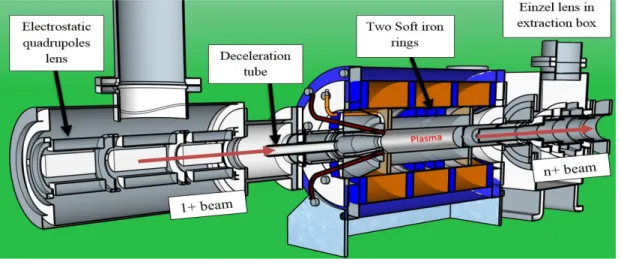
The SPIRAL1 facility at GANIL is dedicated to produce and accelerate the stable and radioactive ion beams which are delivered to physicists for nuclear experimental studies. Extending their research on exotic nuclei properties far from stability, an upgrade has been undertaken at SPIRAL1 to extend the range of post-accelerated exotic beams as well as to provide low energy (keV) radioactive beams to the future DESIR (Désintégration, Excitation et Stockage d'Ions Radioactifs) experimental area. Different Target Ion Source System (TISS) based on a forced electron beam induced arc discharge (FEBIAD) type mono-charged ion source [1] has been chosen to provide 1+ beams of condensable elements with high efficiency. The 1+ beams from TISS are mass analysed and transported to the 14.5 GHz SPIRAL1 ECR charge breeder (CB), which increases the charge state charge of the radioactive ions from 1+ to N+. The extracted high charge state ions are mass analysed and post accelerated to CIME cyclotron (Cyclotron d’Ions de Moyenne Energie) [2].
Figure 1 shows the 3D cross-section of the charge breeder placed in the Low Energy Beam Transport (LEBT) between the TISS and the CIME. In the injection side of the CB the beam is focused with an electrostatic quadrupole triplet and the extracted beam is focused with an einzel lens. The charge breeder has gone through several modifications which are reported in [3], and experimental charge breeding results are presented in [4]. During its operation, a few technical changes have been done in the configuration of the charge breeder: the position of two soft iron rings has been modified to optimize the axial magnetic field and the optimization of the deceleration tube position to study its effect on beam stability and charge breeding efficiency.
Figure 1. 3D view of ECR charge breeder installed between injection and extraction systems in LEBT.
Experimental studies on LEBT transport and charge breeding efficiencies for 23Na+ and 23Na2+ have been carried out to understand the ion losses and 1+ capture processes by ECR plasma.
A rough analysis on the experimental studies is described in the following sections by introducing a simplified ECR plasma model utilizing SIMION 3D. The results obtained from the simulations are presented and compared with the experimental ones.
2. Experimental activities with SPIRAL1 ECR Charge Breeder
2.1 Modification of axial magnetic fieldIn ECR ion source based charge breeders, the “Minimum-B” magnetic field structure is created by 2 or 3 independent solenoids (axial field) and hexapole (radial field) magnets enclosed in an iron yoke. In this configuration, the magnetic field is minimum at the centre of plasma chamber and increases in all directions. The Minimum-B configuration is essential to form a closed resonance surface in the plasma chamber where ECR condition is fulfilled.
Figure 2. Position of two soft iron rings (R1 and R2) around the hexapole.
In SPIRAL1 charge breeder, the axial magnetic field (B) can be adjusted with the center coil and two movable soft iron rings (R1 and R2) placed around the hexapole as shown in Figure 2. Magnetic field calculations were performed with RADIA [5] to study the axial magnetic field profile by adjusting the rings to different positions and significant variations were observed in the size of ECR zone in axial direction. Axial magnetic field profiles for different rings position are shown in Figure 3.
Figure 3. Axial B fields with different positions of the two soft iron rings. a) Two rings joined at the
extraction side of CB (Red) b) Two rings joined at the middle of the hexapole (purple) c) rings separated by 10 mm from the middle of the hexapole (Blue) d) rings separated by 20 mm from the middle of the hexapole (Red). Center of the hexapole refers to the center of plasma chamber (320 mm).
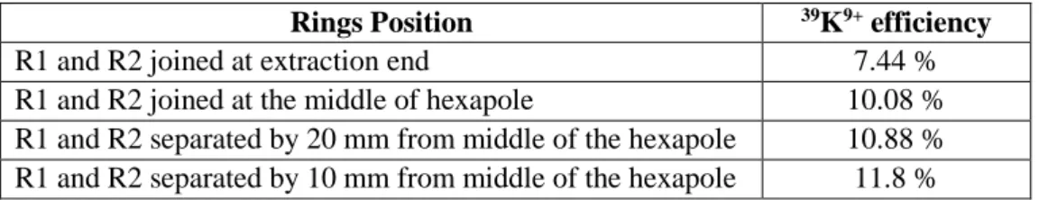
Charge breeding efficiency measurements were performed to study 1+/N+ with potassium beam. Helium was used as buffer gas in CB. During these measurements, the soft iron rings (R1 and R2) were initially pushed towards the extraction end of CB and the charge breeding efficiency of 7.44 % has been recorded for 39K9+. Later, the rings were adjusted to different
positions around the hexapole. Best CB efficiency has been found when the rings R1 and R2 were separated by 10 mm from the middle of the hexapole. Table 1 shows the charge breeding efficiency of 39K9+ with different positions of the two iron rings. As a result, with this
configuration charge breeding efficiency of 39K9+ has been increased by a factor of 1.5 when
compared with initial position of the rings.
Table 1. 39K9+ Efficiency measured at different rings positions. Middle of the hexapole is referred as centre of plasma chamber (320 mm).
2.2 Transmission efficiencies of 39K+ and 23Na+
The 1+ and n+ beam lines have been tuned to achieve maximum ion beam current, up to the Faraday cup (FC1+) and likewise to the Faraday cup (FCn+), which is placed after the charge
0 1000 2000 3000 4000 5000 6000 7000 8000 9000 10000 11000 12000 13000 14000 15000 0 100 200 300 400 500 600 B ( G au ss ) Z (mm)
Axial Magnetic field with different rings position
R1 and R2 joined at the extraction end
R1 and R2 joined at the middle of the hexapole
R1 and R2 separated by 20mm from the middle of the hexapole
R1 and R2 separated by 10mm from middle of the hexapole
Extraction electrode: 457 mm
0.519 T
Rings Position 39K9+ efficiency
R1 and R2 joined at extraction end 7.44 %
R1 and R2 joined at the middle of hexapole 10.08 %
R1 and R2 separated by 20 mm from middle of the hexapole 10.88 % R1 and R2 separated by 10 mm from middle of the hexapole 11.8 %
breeder. Using TraceWin code [6], the beam transport is simulated with potassium and sodium beams in order to achieve high transmission efficiencies in LEBT. Na+ and K+ beams were
produced and injected into the charge breeder with the typical intensities of 300 to 400 nA. By turning OFF the charge breeder (without plasma and high voltage), the transmission efficiency of 80% and 78% on 39K+ and 23Na+ were recorded at faraday cup (FC
n+). The axial B field
configuration was: at injection Binj = 1.41 T, at center Bmin = 0.42 T, at extraction Bext = 0.5 T. 2.3 Charge breeding of 23Na
Hereafter, the experiments were performed with helium as buffer gas in ECR charge breeder, which is observed to be the best for optimizing the charge breeding efficiencies of high charge states of K and Na [7]. Please refer to table 2 for typical values used for charge breeding of Na. The thermionic ion gun was used to produce the 23Na+ beam at an extraction voltage V
1+ = +(20
kV + ΔV). The 1+ ions are mass selected by the 90° dipole and focused through the set of slits where the emittance (4σ) is defined as 30 π.mm.mrad (non-normalized). The beam is focused again by the electrostatic triplet and injected into SPIRAL1 charge breeder with an intensity of 550 nA. The high voltage applied to the charge breeder (VCB) is 20 kV.
Table 2. Parameters used for Charge breeding of 23Na.
The V1+ is regulated through ΔV with respect to the VCB in order to optimize 1+ injection. The
charge bred ions are extracted through extraction system and the required charge state is selected by the bending dipole magnet. Finally, the charge breeding efficiency is calculated as
𝜖𝑐𝑏 = 1 𝐼1+ ∑ ∆𝐼𝑞+ 𝑞+ 𝑞𝑚𝑎𝑥 𝑞=1
Where, ΔIq+ is difference in extracted beam currents with and without 1+ injection, q+ is the required ion charge state and I1+is the injected beam intensity. In this way, the charge breeding efficiencies calculated for 23Na2+, 23Na7+, 23Na8+ and 23Na9+ are 0.82%, 3.23%, 3.57% and 1.2% ,
respectively. The ΔV was tuned between 6 V and 8 V. The ΔV value for maximum achieved efficiency is same for high charge states of sodium, which was similar when compared with results obtained for sodium with LPSC PHOENIX charge breeder [8].
Parameters Charge breeding of 23Na
Magnetic field at injection (Binj) 1.41 T
Magnetic field at injection (Bmin) 0.42 T
Magnetic field at injection (Bext) 0.91 T
RF power (Watts) 540 W
2.4 Effect of deceleration tube position on charge breeding efficiency
In SPIRAL1 charge breeder, the charge breeding efficiencies for 23Na8+ were recorded at different
positions of the deceleration tube. Observing the geometry sub-plot in figure 4, the optimum position is found at a distance of 21 mm from the injection plug of CB. The 23Na+ beam measured
downstream from the charge breeder was stable at the optimum position and became unstable when the tube was moved to the ends. This effect was clearly marginal during the charge breeding test performed with SP1 charge breeder at the 1+/n+ LPSC test bench [4]. This underlines the sensitivity of injection ion optics in LEBT which can affect the injection efficiency and consequently, the charge breeding efficiency.
Figure 4. Effect of deceleration tube position on Na8+ charge breeding efficiency. At 0 mm, the position of the tube is inside the charge breeder. Measured Na8+ curves are normalized to 1 3.65%.
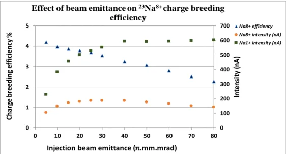
2.5 Effect of injected beam emittance on charge breeding efficiency
Figure 5. Effect of beam emittance on Na8+ charge breeding efficiency. 0 1 2 3 4 0 10 20 30 40 50 60 70 80 90 100 Ch ar ge br ee di ng ef fi cien cy %
Deceleration tube position (mm)
Effect of deceleration tube on Na8+ charge breeding efficiency
Na8+ measured Deceleration tube plasma chamber 21 mm 0 100 200 300 400 500 600 700 0 1 2 3 4 5 0 10 20 30 40 50 60 70 80 In tens it y (n A ) C h ar ge b ree d in g ef fi cien cy %
Injection beam emittance (π.mm.mrad)
Effect of beam emittance on 23Na8+ charge breeding efficiency
Na8+ efficiency Na8+ intensity (nA) Na1+ Intensity (nA)
The 20 kV 23Na+ beam was injected into SPIRAL1 charge breeder with an intensity of 550nA.
ΔV was optimized in order to reach a Charge breeding efficiency of 3.53% on 23Na8+. The
injection beam emittance defined for this measurement is 30 π.mm.mrad (non-normalized). Later, the injected beam emittance was then varied from 5 π.mm.mrad to 80 π.mm.mrad by adjusting a set of slits between the 1+ source and the CB. The intensities of Na1+ and Na8+ beam is recorded
at the Faraday cup (FC1+) placed before the injection optics of the charge breeder and Faraday
cup (FCn+) placed in n+ line after the mass analyzer. Figure 5 represents the 23Na8+ charge breeding
efficieny and 1+/8+ intensities as a function of injected beam emittance. At low emittance (< 40 π.mm.mrad), the 1+ beam that is actually injected into the charge breeder is collimated by the set of slits, which represents a significant drop in 1+ beam current. Consequently, the n+ current has shown a significant drop at low emittance which is due to the injection of low 1+ intensity into the charge breeder. At higher emittance (> 50 π.mm.mrad), a small drop in Na8+ beam currents
has been observed. It suggests that perhaps increased ion losses in the injection region affecting the injection efficiency. The observed charge breeding efficiency trends steadily decrease with increase in emittance.
3. Numerical simulation studies on ECR charge breeder
3.1 Simulation descriptionNumerical simulations were performed to evaluate the ion losses during the transport of 1+ beam through the charge breeder with and without a simplified model of the ECR plasma. These cases correspond with the situations where the CB is operated in shooting-through mode and charge breeding mode. Figure 6 represents the geometry of Low Energy Beam Line from the beam slits position to the extraction system of the charge breeder was implemented in a particle tracking code called SIMION 3D [9]. The geometry includes the injection optics (electrostatic quadrupole lens, deceleration tube), SPIRAL1 charge breeder and extraction system. The 3D magnetic field of the CB is externally calculated from RADIA and given as an input for the simulations. The electric fields are calculated in SIMION by applying potentials to the geometry electrodes. For initiating the ions in the simulation, a Matlab code has been developed, which can generate the initial ions using beam properties (twiss parameters and transversal co-ordinates) obtained from TraceWin code (α = -2.3019, β = 0.7715). The particles created in the Matlab code should satisfy the following phase space relations in order to be a part of the beam.
𝛾𝑥2+ 2𝛼𝑥𝑥′+ 𝛽𝑥′2 ≤ 𝜖 𝛾𝑦2+ 2𝛼𝑦𝑦′+ 𝛽𝑦′2 ≤ 𝜖
Also, the energy and mass of 1+ ions can be changed in the code to simulate the ions with different mass and energies. The input file is written as ion mass, ion charge state, position of particle in x, y, z , angles (x’, y’) which satisfy the above relations and ion energy. In this way, the starting conditions for the simulation are defined.
3.2 Ion transport through the charge breeder without plasma
The transmission efficiencies obtained for 39K+ and 23Na+ ions are discussed in the previous
section. When the high voltage of CB is OFF (shooting-through), transmission efficiencies were recorded.
Figure 6. The geometry of electrostatic quadrupole lens (a), decleration tube (b), ECR charge breeder (c)
and extraction einzel lens (d) used in the ion transport simulation. At the point E, 10000 39K+ ions are initiated with the energy of 10 keV and simulated through ECR charge breeder. The total ions extracted from charge breeder are counted after the extraction system.
Later, the potential of CB is ramped from 1-15 kV and observed an increase (also decrease) in efficiency. To understand these fluctuations, 39K+ and 23Na+ ions at energy of 10 keV and 15 keV
are simulated through the CB with an emittance of 50 π.mm.mrad (non-normalized) at the characterization point E. The emittance used for this case is similar to the experimental ones. Figure 6 shows the simulation of 39K+ ions transported through the CB. The ion losses are
monitored in the simulation by writing a dedicated Lua user program. In the simulation, z-axis is taken as reference axis. The program records the particle count before and after the injection optics, charge breeder and extraction system. The transmission efficiency is calculated by considering the ratio between the total extracted particles from the charge breeder and total particles injected into the charge breeder. In both cases (K+ and Na+), the simulation has shown
that up to 20% of 1+ ions were lost at the extraction aperture. 3.3 Ion transport through the Charge Breeder plasma
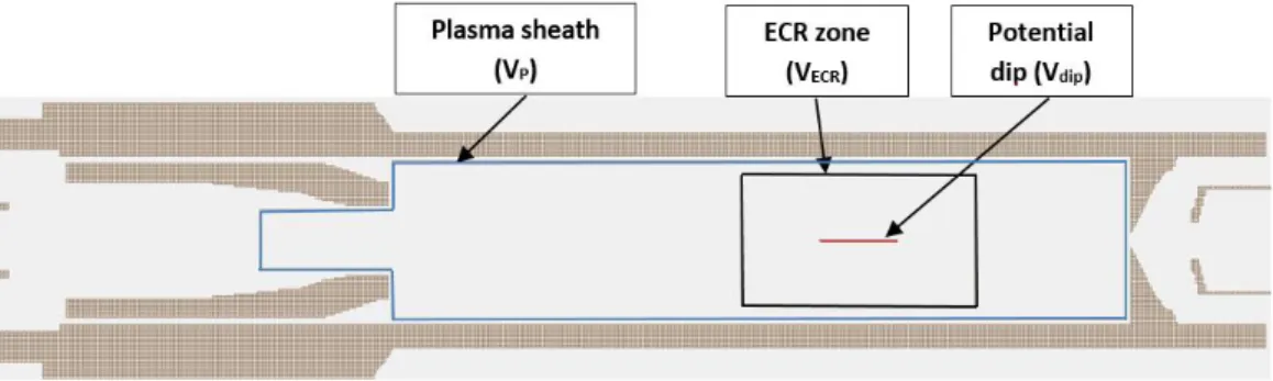
In this case, the numerical simulation basically simulates the ion transport through a simplified plasma model introduced in the charge breeder, which allows to reproduce the trends of experimental ΔV curves. The CB geometry was modified by including a thin cylindrical symmetry electrode of plasma sheath (Vp), ECR zone (VECR) and potential dip (Vdip) inside the
ECR zone. Fixed potentials are given to these electrodes to approximate the potential distribution in plasma volume. The sheath created by the plasma is considered to be contained within the two maxima of the magnetic field, thus the contour is extended from the maximum at the injection up to the extraction electrode. The distance between the wall and sheath is 1mm/grid cell. The geometry of ECR zone is located at minimum-B structure formed by the three solenoids. It has been argued [10] that the potential dip should be formed inside the ECR zone and simulations were performed regarding the processes in ECRIS [11], where the potential dip is confined inside the ECR zone. From these references, the potential dip is implemented inside the ECR zone in order to see its effect on trends of ΔV curves. The potentials applied to the sheath (Vp) and ECR
zone (VECR) are always equal in all cases in order to confine the potential dip inside the resonance
zone.
To consider the deceleration of 1+ ions, the potentials applied to the geometry of plasma potential (Vp) and ECR zone (VECR) is higher than the potential of charge breeder (Vcb). The
potential dip is always considered as Vdip = VECR -1 V. The plasma potential of 10 V has been
chosen in order to reproduce the ΔV curves. However, based on experimental optimum ΔV results we know that the plasma potential in reality is lower, most likely below 8 V. But in order to simulate the trends, this discrepancy should not be critical. Ions are initiated with an emittance of 30 π.mm.mrad at energy of 20 keV. The ΔV curves for Na1+ in the simulation are defined as the
potential difference between the charge breeder and injection energy of 1+ ions. Besides, the idea of simulating Na2+ ions through the simplified plasma model has been implemented to see the
evolution of Na2+ ΔV curves. As the simplified plasma model presented in this paper does not
include collisions or other interactions between the ions, the Na2+ ions are initiated at three
different locations inside the plasma chamber. A dedicated Lua program has been written to initiate the Na2+ after overcoming the potential barrier, at the boundary of ECR surface and inside
the ECR surface. Using this program, the mass and charge of an ion can be changed without disturbing the kinetic energy of ions. The efficiency is finally calculated at the end of extraction system as the ratio between number of particles extracted and number of particles injected.
4. Simulation Results and discussion
With the transmission simulations (CB off), Transmission efficiencies of 84% and 79% for K+
and Na+ were recorded after the extraction system, which are very similar to the experimental
results reported in the previous sections. From the observations, 100% transmission has been achieved up to the entrance of CB. The ion losses were observed only at the extraction aperture. Ion losses significantly increase at extraction aperture with increase in Vcb.
Figure 8. Normalized efficiency of Na+ as a function of ΔV. Measured and simulated curves are normalized to 1 from 28% and 24%.
The second part of the numerical simulation concerned the extraction of Na+ and Na2+
through CB plasma volume. From the observations, the recorded simulated curve seems to shift towards higher ΔV when compared with experimental curves. In order to find the best agreement
0 0.1 0.2 0.3 0.4 0.5 0.6 0.7 0.8 0.9 1 0 10 20 30 40 50 60 70 80 90 100 110 120 130 140 N o rm al iz ed Ef fi ci ency ΔV (V) ΔV for Na1+ Na1+ measured Na1+ simulated
with the experimental curves, the emittance of 1+ beam has been varied to 20 π.mm.mrad by keeping the same twiss parameters. At low ΔV, most of the ions are reflected back to the deceleration tube due to positive plasma potential (e.g. 85% of ions with ΔV between 9 - 10 V). When ΔV is at 55 V, the maximum of the Na+ is obtained, and the ion losses at the entrance of
plasma chamber significantly decreased to 15%. In case of Na2+, the ΔV curves are recorded at
three different locations as explained in the previous section. The ΔV curves of Na2+ ions which
are initiated at the boundary of ECR surface agree with the experimental data and presented in Figure 9. The simulation seems to significantly over-estimate the efficiency compared to the measured values. This is probably due to the very simplified 1+ to 2+ conversion model implemented in the simulations.
During the simulations, periodic oscillations were observed after 50V and higher, which was also observed in Na+ experimental curves. These discrepancies observed in the simulations
revealed that the 1+ (and maybe 2+) beam traversing through the plasma chamber exhibits a periodic focusing/defocusing behavior due to the solenoid field [12], and consequently the phase of this motion at the extraction aperture influences the transmission. As this motion is ion energy dependent, varying ΔV or Vcb influences the phase at the extraction aperture and therefore the
transmission. Thus this phenomenon can explain some of the features seen in the simulation results (oscillating transmission). As similar oscillations are present in measured data, it suggests that perhaps similar effects takes place in reality. Also, the potential dip is varied by few volts and its effect was found to be negligible for the trends of ΔV curves.
Figure 9. Normalized efficiency of Na2+ as a function of ΔV. Measured and simulated curves are normalized to 1 from 0.9% and 21%.
Summary and perspectives
Simulations revealed that the ion losses at the extraction aperture are mostly due to the beam oscillations in the charge breeder. The transmission efficiencies obtained from the simulations show good agreement with the experimental results. The ΔV plots for Na+ and Na2+ obtained from
a rough analysis performed with the simplified ECR plasma model has shown similar trends when compared with the experimental curves. In the future, the simulation model presented in this paper will be improved by distributing the Na2+ ions randomly in the core of ECR plasma instead of
using a conversion from 1+ to 2+ at a fixed axial position. Simultaneously, the ΔV plots for Na+ 0 0.1 0.2 0.3 0.4 0.5 0.6 0.7 0.8 0.9 1 0 10 20 30 40 50 60 70 80 90 100 110 120 130 140 N o rm al iz ed E ff ici en cy ΔV (V) ΔV for Na2+ Na2+ measured Na2+ simulated
and Na2+ will be calculated with a numerical simulation code called MCBC (Monte Carlo Charge
Breeding Code) which can model the capture and charge breeding of a beam of ions injected into plasma [13]. The ΔV plots obtained from SIMION 3D and MCBC will be compared for further investigation regarding the 1+ capture process by ECR plasma. To complete this analysis, additional experimental data will be gathered from Mg (using He buffer gas) and K (using He and O2 buffer gas) charge breeding efficiency (also charge breeding time) measurements. This
approach can show a possible way to determine the tendency of charge breeding parameters which influences the 1+ ion capture efficiency by the ECR plasma.
References
[1] O. Kamalou et al., GANIL Operation Status and New Range of Post-Accelerated Exotic Beams, in Proceedings of the 13th International Conference on Heavy Ion Accelerator Technology, pp.20-22 (2015).
[2] M. Duval et al., New compact cyclotron design for SPIRAL, in Proceedings of the 14th International Workshop on Magnet Technology, MT-14 Tampere, Finland, June 11-16 (1995).
[3] P. Delahaye et al., Charge breeding of light metallic ions: Prospects for SPIRAL, Nuclear Instruments and Methods in Physics Research, A 693 104 (2012).
[4] L. Maunoury et al., SPIRAL1 Charge Breeder: Performances and Status, in Proceedings of the 22nd International Workshop on ECR Ion Sources, Busan, South Korea, 28th August- 1st September (2016).
[5] RADIA magnetic field simulation code,
http://www.esrf.eu/Accelerators/Groups/InsertionDevices/Software/Radia [6] http://irfu.cea.fr/dacm/logiciels/
[7] L. Maunoury et al., Charge breeder for the SPIRAL1 upgrade: Preliminary results, Review of Scientific Instruments, 87, 02B508 (2015).
[8] T. Lamy et al., in Proc. of the 18th International Workshop on ECR Ion Sources, Chicago, Illinois, US, September 15-18, 2008.
[9] SIMION Ion and Electron Optics Simulator, http://www.simion.com
(ScientificInstrumentServices,Inc.(SIS))
[10] V. Mironov et al., Numerical model of electron cyclotron resonance ion source, Physical review special topics-accelerators and beams 18, 123401 (2015).
[11] B. Cluggish et al., Simulation of parameter scaling in electron cyclotron resonance ion source plasmas using the GEM code, Review of Scientific Instruments, 81, 02A301 (2010).
[12] V. Kumar, Understanding the focusing of charged particle beams in a solenoid magnetic field, American Journal of Physics, 77. 737 (2009).
[13] JS. Kim et al., Ion beam capture and charge breeding in electron cyclotron resonance ion source plasmas, Review of Scientific Instruments, 78, 103503 (2007).