Design and Development of Mechanical Metatarsophalangeal Joint for Powered
Ankle-Foot Prostheses I
by
Jasmin Elena Palmer
MWASSAUSEbtTSbM IITITUIt
OF TECHNOLOGYL
JUL 16
2019
LIBRARIES
ARCHIVES
Submitted to the Department of Mechanical Engineering in Partial Fulfillment of the Requirements for the Degree of
Bachelor of Science in Mechanical Engineering at the
Massachusetts Institute of Technology
June 2019
C 2019 Massachusetts Institute of Technology. All rights reserved.
Signature redacted
Signature of A uthor: ... ... Department of Mechanical Engineering
Signature
redacted
C ertified b y : ... ...
Hugh Herr Professor of Media Arts and Sciences Thesis Supervisor
Signature redacted
C ertified by : ...
Design and Development of Mechanical Metatarsophalangeal Joint for Powered
Ankle-Foot Prostheses
by
Jasmin Elena Palmer
Submitted to the Department of Mechanical Engineering on May 10, 2019 in Partial Fulfillment of the
Requirements for the Degree of
Bachelor of Science in Mechanical Engineering ABSTRACT
This thesis seeks to explore passive designs for a mechanical alternative to the metatarsophalangeal (MTP) joint, a critical anatomical component in human feet which allows for various types of anatomical motion. Our goal is to design a system that will act as a platform to test a proof of concept for a passive ankle-foot prosthesis with an MTP joint, but can also be adapted to use an actuated joint in the future. To increase the user's range of motion, our aim was for the mechanical MTP joint to achieve a maximum 600 dorsiflexion angle. We developed 2 MTP joint designs (Rubber Hinge and Fabric Hinge) with 2 body geometries varying at the heel for each (Traditional Heel and Inverted Heel) for a total of 4 models. We performed a static load Finite Element Analysis
(FEA) using the Solidworks FEA Simulation Tool. The FEA was performed under the worst-case
static load scenarios for the toe and body components of the prosthesis, standing on tiptoe with a dorsiflexion angle of 60' for the toe components and standing with all weight on the heel for the body components. The simulation yielded that not only did no components experience any irreversible deformation, but that the Rubber Hinge design had a minimum safety factor of 5.7, 10, and 4.5 for the Toe, Inverted Heel Body, and Traditional Heel Body respectively and the Fabric Hinge Design had a minimum safety factor 1.4, 9.9 and 4.5 for the Toe, Inverted Heel Body, and Traditional Heel Body respectively. This informed us that though both designs did not undergo failure under the prescribed loads, material utilization was in excess and could be further optimized to decrease the weight. Future designers should focus on implementing this platform into high fidelity physical models to be tested under various static and dynamic loading conditions as well as further optimizing the dimensions of the prosthesis.
Thesis Supervisor: Professor Hugh Herr Title: Professor of Media Arts and Sciences
Acknowledgments
The author would like to first thank my family for their unconditional love and support throughout my four years at MIT. I also want to thank my advisors and mentors who have guided me to this point.
Special thanks to Matt Carney for helping guide this thesis, providing the initial concept models that jumpstarted this project, and giving advice on mechanical design.
Finally, thank you Professor Herr and the MIT Media Lab Biomechatronics Group for providing the resources to make this work possible.
Table of Contents
Abstract 2 Acknowledgements 3 Table of Contents 4 List of Figures 6 1. Introduction 8 1.1 Motivation 8 1.2 Objective 9 2. Design Requirements 122.1 Range of Motion and Biomimicry 12
2.2 Torque Requirement 13
3. Background and Theory 14
3.1 Young's Modulus 14
3.2 Three-Point Flexure Test Theory 14
3.3 Quantitative Derivation of Geometry 14
3.3.1 Determination of Overall Dimensions 14
3.3.2 Torque and Stress Equations 15
4. Experimental Design 16
4.1 Determination of Elastic Modulus of Parallel Spring Beams 16
5. Design Process 18
5.1 Design Iterations 19
5.1.1 The Concept Model 19
5.1.2 Shaft and Bearing Design 22
5.2 Flexural MTP Joints and Heel Designs 26
5.2.1 Rubber Hinge Design 26
5.2.2 Fabric Hinge Design 29
5.3 Finite Element Analysis 31
5.3.1 Toe 32
5.3.3 Inverted Heel Body 33
6. Results and Discussion 35
6.1 Young's Modulus of Parallel Spring Beams 35
6.2 Determining Appropriate Material Thickness 36
6.3 Finite Element Analysis 36
6.3.1 FEA Results of the Components from the Rubber Hinge Design 37
6.3.2 FEA Results of the Components from the Fabric Hinge Design 38
7. Conclusions and Future Work 41
8. Appendix: Other Design Concepts Considered But Not Fully Explored 42
List of Figures
Figure 1: Lower-limb prostheses from 1915 to 2015 8
Figure 2: Ankle-foot prostheses by MIT Media Lab Biomechatronics Group 9
Figure 3: Location of the MTP Joint relative to other anatomical structures 10
Figure 4: Schematic representation of how the dorsiflexion angle is defined 12 Figure 5: CAD concept model of an ankle-foot prosthesis with MTP joint 13
Figure 6: Foot proportions 15
Figure 7: Spring beam dimensions 16
Figure 8: Schematic representation of the 3-point flexure test 17
Figure 9: Schematic representation of the machine compliance test 17
Figure 10: Defining sections of the prosthesis 18
Figure 11: Overall dimensions of the LP Vari-Flex prosthetic foot by Ossur 19
Figure 12a: Side view of Concept Model CAD 20
Figure 12b: Isometric view of Concept Model CAD 20
Figure 13: Concept sketches for making the prosthesis entirely passive 21
Figure 14: Shaft and Bearing Model design sketches 23
Figure 15a: Side view of Shaft and Bearing Model design CAD 24
Figure 15b: Isometric view of Shaft and Bearing Model design CAD 24 Figure 16a: Shaft and Bearing Model CAD cross-section of hinge at 0' dorsiflexion 24 Figure 16b: Shaft and Bearing Model CAD cross-section of hinge at 60' dorsiflexion 24
Figure 17: Physical model of the Shaft and Bearing Model 25
Figure 18: Rubber Hinge design with Inverted Heel Body concept sketches 27
Figure 19: Rubber Hinge design with Inverted Heel Body CAD model 28
Figure 20: Rubber Hinge design with Traditional Heel Body concept sketches 28
Figure 21: Rubber Hinge design with Traditional Heel Body CAD model 29
Figure 22: Fabric Hinge design with Inverted Heel Body sketches 30
Figure 23: Fabric Hinge design with Inverted Heel Body CAD model 31
Figure 24: Fabric Hinge design with Traditional Heel Body CAD model 31
Figure 25a: Side view of loaded state of Toe from Rubber Hinge design standing on tiptoe 32
Figure 25b: Isometric view of loaded state of Toe from Rubber Hinge design standing on
tiptoe 32
Figure 25c: Side view of loaded state of Toe from Fabric Hinge design standing on tiptoe 32
Figure 25d: Isometric view of loaded state of Toe from Fabric Hinge standing on tiptoe 32
Figure 26a: Side view of loaded state of Traditional Heel Body from Rubber Hinge design with
all user body weight on heel 33
Figure 26b: Isometric view of loaded state of Traditional Heel Body from Rubber Hinge design
with all user body weight on heel 33
Figure 26c: Side view of loaded state of Traditional Heel Body from Fabric Hinge design with
all user body weight on heel 33
Figure 26d: Isometric view of loaded state of Traditional Heel Body from Fabric Hinge design
with all user body weight on heel 33
Figure 27a: Side view of loaded state of Inverted Heel Body from Rubber Hinge design with all
user body weight on heel 34
Figure 27b: Isometric view of loaded state of Inverted Heel Body from Rubber Hinge design
Figure 27c: Side view of loaded state of Inverted Heel Body from Fabric Hinge design with all
user body weight on heel 34
Figure 27d: Isometric view of loaded state of body with Inverted Heel from Fabric Hinge design
with all user body weight on heel 34
Figure 28: Data from the 3-point flexure and machine compliance tests 35
Figure 29a: Required minimum yield stress of material for a toe component 36
Figure 29b: Required minimum yield stress of material for a body component 36
Figure 30a: FEA results of Toe from Rubber Hinge design 37
Figure 30b: FEA results of Traditional Heel Body from Rubber Hinge design 38
Figure 30c: FEA results of Inverted Heel Body from Rubber Hinge design 38
Figure 31 a: FEA results of Toe from Fabric Hinge design 39
Figure 31b: FEA results of Traditional Heel Body from Fabric Hinge design 39
Figure 31 c: FEA results of Inverted Heel Body from Fabric Hinge design 40 Figure 32: Alternate hinge design sketches using a shaft and bearing 42
Figure 33: Living hinge design concept sketches 43
Figure 34: Two-joint design concept sketches 44
1. Introduction 1.1 Motivation
People have been designing and fabricating prostheses for most of recorded history. In fact, the earliest known record of a lower-limb prosthesis dates back to the writings of the Rigveda, one of the four sacred Hindu canonical texts of the Vedas, written circa 1700-1100 BC. Prostheses have also been discovered in the tombs of ancient Egyptians of the New Kingdom (circa
1550-1069 BC), a testament to the importance of such devices, as in their culture, a person was buried
with the things most important to them which they believed would be needed in their eternal resting place.
Prostheses not only provide some mobile functionality for people with loss of limb, but also emotional support by helping mitigate the effects of loss of mobility and social stigma associated with disability.
As our technology improves, prosthetic devices have been able to evolve from the cosmetically anthropomorphic wooden and metal limbs such as those worn by the ancient Indians and Egyptians to more practical components designed using advanced analytical techniques, composite materials, and computer aided design (CAD).
Figure 1: Prosthetic legs developed from 1915 to 2015 showing the wide variation in
design of lower-limb prosthetic devices and the improvements that need to be made to restore normal functionality [1].
4
Figure 2: Various modem ankle-foot prostheses developed by the MIT Media Lab
Biomechatronics Group [2].
Because the study of prosthetic design is broad in scope and challenge, this thesis will focus on the design of ankle-foot prostheses with a mechanical alternative to the metatarsophalangeal (MTP) joint. Though a problem nearly as old as civilization, the design of ankle-foot prostheses proposes unique challenges and improving ankle-foot prosthetic design and functionality is becoming more imperative.
Improving ankle-foot prostheses would increase the quality of life for people with loss of lower-limb since so much of typical daily routine revolves around ambulation. The need for improved lower-limb prostheses, especially for transtibial (below the knee) amputees is increasing on multiple fronts. For instance, the number of people in the United States living with the loss of a limb is expected to increase from 1.6 million in (in 2005) to 3.6 million by 2050. The majority of this rise is due to the increasing pervasiveness of an aging population and dysvascular conditions as a result of diabetes, a progressively more prevalent issue in the United States and other developed nations [3]. Despite the growing body of research, current ankle-foot prosthetic technology is insufficient for restoring full functionality of natural human ankles and feet.
1.2 Objective
The objective of this thesis is to develop a more biomimetic platform for the foot component of a powered ankle-foot prosthesis that interfaces with the MIT Media Lab Biomechatronics Group's (Biomech) powered ankle prosthesis.
A critical anatomical component of the foot missing from current ankle-foot prosthetic devices
is the MTP joint. The MTP joint is located between the metatarsal bones of the foot and proximal bones of the toes as shown in Figure 3 and allows for various types of anatomical motion such as flexion, extension, abduction, adduction, and circumduction in the foot. The MTP joint plays a critical role in maintaining the human body's balance while standing and providing the push-off force for normal locomotion such as walking, running, and jumping [4].
distal phalanges rniddle phalanges
distal Interphalangeal joints poia hlne
proximal phalanges
proximal Interphalangeal joints metatarsal bones
tarsal bones
metatarsophalangeal joints
calcaneus (heel bone)
talus
Figure 3: Visual representation of the anatomical location of the MTP joint in a human
foot relative to other critical structures [5].
Currently, most modem ankle-foot prostheses rely on a semi-rigid foot plate, which effectively eliminates the degrees of freedom provided by the 33 joints in each human foot, therefore limiting mobility and altering the kinematics and kinetics of the ankle. This results in limitations in biological accuracy of motion for the user. Additionally, the deficiencies of passive (unactuated) prostheses force a user to compensate by adjusting their overall body motions, potentially leading to later physiological complications which affect the mobility and quality of life of people living with loss of lower-limb [6].
To solve this issue, many researchers have taken various approaches to ankle-foot prosthetic design. As explored by Biomech, powered ankle-foot prostheses offer a solution for regaining lost functions by applying net positive torque to the ground, which cannot be replaced by a passive prosthesis, in order to normalize walking gait [7]. Though an improvement from the passive devices used by most amputees, these powered prostheses still fail to restore full function provided
by natural human feet and ankles.
This thesis seeks to explore passive ankle-foot prosthetic designs and proposes that a more biomimetic platform providing additional degrees of freedom that mimic biological motion by developing a mechanical alternative to the MTP joint. The new platform would offer improved mobility for users by further normalizing gait and decreasing the metabolic cost relative to current passive prostheses. A hypothesis is that enabling more biologically accurate kinematics while being coupled to a powered ankle would reduce the energetic cost of walking for users. This would thus further advance the state of the art of robotic prostheses and human augmentation.
There are numerous advantages to pursuing a passive design. To name a few, passive prostheses are cheaper, simpler, and easier to maintain than powered prostheses. Passive systems are also lighter in weight compared to active systems due to their lack of electromechanical components, which would potentially aid in decreasing metabolic cost for the user [8]. The design of a passive foot working in conjunction with an active ankle prosthesis may help make this kind of system more accessible for widespread use.
The development of such a device would result in increased independence for those with limited mobility due to transtibial amputation and deepen our understanding of the effect of mechanical alternatives to active foot joints on human biomechanics and locomotion.
Our goal is to establish and design a system that will act as a platform to test a proof of concept for a passive ankle-foot prosthesis with an MTP joint, but can also be adapted such that a fully actuated design with user neuro-motor control can be implemented in the future.
2. Design Requirements
2.1 Range of Motion and Biomimicry
To provide the user with an increased range of motion, we aim for the design of the mechanical
alternative of the MTP joint to achieve a 600 dorsiflexion angle as shown below in Figure 4. In order to add some control of the angle, the design will make use of a cantilever beam spring made of glass fiber by Gordon Composites (GC-70-UL) to support toe flexion and prevent total free rotation.
0
Figure 4: A schematic representation of how the dorsiflexion angle, 6, is defined relative to a typical human foot.
We also aim to decrease the form factor of the previous design created by Biomech's concept model as shown in Figure 5. It is most desirable to make the prosthesis as lightweight as possible
by maximizing material utilization such that it is ideally substantially lower mass than a biological
Figure 5: Solidworks CAD model of Biomech's concept of an ankle-foot prosthesis with
mechanical alternative to the MTP joint.
In addition, since we aim to produce a biomimetic design, we will bound the overall dimensions of the prosthesis to be no larger than the dimensions reasonable for human feet [9].
2.2 Torque Requirement
One of our key metrics of interest is the torque about the MTP joint at 600 of dorsiflexion. There is very limited research on the torques specifically about the MTP joint. Of the research on the subject of MTP joint torque, the application has been toward measuring this value for human feet, not mechanical devices, as the current most commonplace prostheses are essentially cantilever beams.
A study by Man et al. quantified the stiffness of the MTP joint by developing a dynamometer
and procedure for measurement of the MTP joint and ankle joint. They measured the torques for
19 subjects over 2 separate days within the same week. Their results yielded that the average torque
about the MTP joint was 1.34 0.39 Nm/degree [4].
These results provide us with a baseline for the order of magnitude of which we can expect the prosthesis to need to withstand. This seems reasonable as other researchers have obtained results within a similar order of magnitude [10]. From this information, we can expect the maximum torque on the MTP joint to be 1.73 Nm/degree, therefore having a maximum possible torque of
3. Background and Theory 3.1 Young's Modulus
To make use of the parallel spring beam as a component to limit free rotation of the MTP joint, we need to evaluate an important mechanical property, the Young's Modulus, E for the parallel spring beams. The Young's Modulus is an intrinsic material property that quantifies that material's resistance to changes in length due to applied tensile or compressive forces. It is critical in determining the limits of the dimensions needed such that the prosthesis will not undergo material failure by way of plastically (or permanently) deforming under load, or in the worst-case scenario, fracture.
3.2 Three-Point Flexure Test Theory
A 3-point flexural test is performed by placing a simply supported beam of length L under a
point load at its mid-span, L/2. The deflection of the mid-span of such a beam as shown in Figure
8 is defined by
PL3
S= 48EI481(1)
where P is the load applied to the beam, E is the Young's Modulus, and I is the area moment of inertia.
For a specimen with a rectangular cross section, I is expressed as
bh3 (
I = (2)
12
where b and h are the width and height dimensions of the specimen as defined in Figure 7.
We used an Instron universal testing machine to apply a controlled load to the mid-span over a range of 0 N to 1000 N such that the testing would remain non-destructive to the specimen. Because the machine itself will deflect due to the load applied by the machine, this will have to be accounted for by defining a "real" deflection to make a more accurate determination of E. The "real" deflection will be defined by
GReal = Beam - 6Machine (3)
where both SBearn and 6Machine can be directly obtained from the Instron machine output.
3.3 Quantitative Derivation of Geometry
3.3.1 Determination of Overall Dimensions
We established bounds for our design by dividing the foot into 4 proportional sections, similar
to a real human foot. These sections were the toe, ball of foot including MTP joint, arch, and heel. The toe, ball of foot, arch, and heel are proportioned by x, x , 2x, and x respectively where x is some fraction of the overall length of the prosthetic foot as shown in Figure 6. Since the overall
length of the prosthetic foot in this design is 250 mm each value of x is 50 mm. We also made the prosthetic foot 60 mm wide. Deciding to proportion sections of the prosthesis in this manner was necessary to solve force balance and moment balance equations.
x
2x
x
x
Figure 6: A schematic representation of the 4 proportional sections of the foot in relation
to each other [11]. The toe, ball of foot, arch, and heel are proportioned by x, x , 2x, and x respectively where x is some fraction of the overall length of the prosthetic foot.
3.3.2 Torque and Stress Equations
For the purposes of the thesis' scope we define the torque about a point defined in a right-handed coordinate system to be
TA = TA*B X EB (4)
where i*A represents the torque at a point of interest, A, FB represents a force applied at another
point B, and iA_,B represents the lever arm distance between points A and B. Since the aforementioned equation does not directly rely on material properties, our data can be analogized to other materials that could be used by a human subject.
In a solid material we can define the stress a as the force per area of a material such that
= (5)
A
and the stress is in units of N/m2 . Additionally, the stress a of a beam in bending is
qxx = E MExx (6)
where E represents the Young's Modulus, I represents the area moment of inertia, E represents the strain, M(x) represents the moment distribution along the material, and y represents the distance from the neutral axis.
4. Experimental Design
4.1 Determination of Elastic Modulus of Parallel Spring Beams
To confirm the Young's Modulus of the material we will use for the parallel spring beams, we
performed a 3-point flexure test as discussed in Section 3.2. We subjected a sample of the material with dimensions L = 120.1 mm, b = 15.09 mm, and h = 3.30 mm as shown in Figure 7 to a
vertical load perpendicular to the cross-sectional area for an incrementing range of forces with the Instron machine up to 1000 N. We measured the deflection of the beam's midpoint with respect to the zero load condition as shown in Figure 8.
7
jthL
Figure 7: A schematic representation of the spring beam represented in blue used. A
3-point flexure test was performed on this specimen to derive the Young's Modulus, E. L, b, and h represent the length, width, and height dimensions of the specimen respectively.
Since the machine has its own compliance, we made the machine apply load against itself up to 1200 N as shown in Figure 9 and measured the deflection due to this applied load. We subtracted the machine deflection from the spring beam deflection to get the true deflection of the beam and
used that value to obtain a more precise value for Young's Modulus.
By knowing the deflection of the beam's midpoint and the deflection due to the machine's
compliance, we can rearrange the equation described in Section 3.2 Equation I to determine the Young's Modulus by substituting Real for 6.
P
SBeam_= 0
Beam
70 mm
Figure 8: A schematic representation of the 3-point flexure test for deriving the Young's
Modulus, E. The spring beam represented in blue was placed under load ranging from 0 N to 1000 N. The deflection of the midpoint was measured with respect to the SBeam = 0 line over the range of the load. This value was used to derive E.
IP
6
Machine
Machine 0
7717
Figure 9: A schematic representation of the machine compliance test for deriving the
Young's Modulus, E. The machine was placed under load ranging from 0 N to 1200 N. The deflection of the machine was measured with respect to the 6machine = 0 line over
5. Design Process
To approach a design that fulfills most or ideally all of the design requirements discussed in
Section 2, we used an iterative design process. In discussion of these designs, the toe component will be referred to as the "toe", the mechanical alternative to the MTP joint will be referred to as the "hinge" and the section relating to the arch and heel will be referred to as the "body" as described in Figure 10.
Figure 10: Visual representation of the toe, hinge, and body sections of the prosthesis. This
figure is making use of the Concept Model as an example of what sections of the prosthetic foot are being referred to when using the terms "toe" (blue), "hinge" (green) and "body" (red).
We constrained the dimensions of the prosthesis such that overall length, width and height are 250 mm, 60 mm, and 30 mm respectively. Though according to the study by mentioned in Section
2.1, width should be closer to 90 mm, we can vary the width, b. Since I is cubically correlated to
h but only linearly correlated b, the decrease in width is essentially negligible so this is a good
place to save on material. Also, other currently available foot prostheses such as the LP Vari-Flex prosthetic foot by Ossur has dimensions (without the connector) of approximately 222.5 mm, 63.5 mm, and 25.4 mm, for the overall length, width, and height respectively as shown in Figure 11 so
N11
25.4 mm
63.5 mm
222.5 mm
Figure 11: Visual representation of the overall dimensions of the comparable device, the
LP Vari-Flex prosthetic foot by
Ossur
[12].5.1 Design Iterations
5.1.1 The Concept Model
Our starting point was a concept Solidworks model, referred to as Concept Model, as shown in Figure 12 developed by Biomech. The dimensions of this design were not derived via analyzing the load state of the prosthesis at 600 dorsiflexion nor is there a place for the powered ankle prosthesis to interface with this device. The Concept Model features a capstan-pulley system intended to be connected to an actuator, which would be ineffective in a passive device such as the one we aspire to develop. However, the overall length, width, and height dimensions, as well as the use of parallel spring beams to provide a force to aid in returning the toe to 0' dorsiflexion will remain in some capacity throughout later models.
oO
0
-(a) (b)
Figure 12: Original concept CAD for MTP joint ankle-foot prosthesis. Panel (a) is a side
view and Panel (b) is isometric. This design features a capstan-pulley system intended to be connected to an actuator in order to control the dorsiflexion angle of the MTP joint. The overall length, width, and height dimensions, as well as the use of parallel spring beams will remain in some capacity throughout later models.
To improve upon the Concept Model, multiple alternative hinge and body mechanisms were sketched as shown in Figure 13 to convert this model into an entirely passive system.
C 444c W t La _ i4 4 ~V&TeL -In ... ) 'ee
\ Lne .* c &+ C A54f Cr-0 cor' 44T
d 6
Figure 13: Sketches depicting ideation process for making the system entirely passive as
an improvement to the Concept Model.
5.1.2 Shaft and Bearing Design
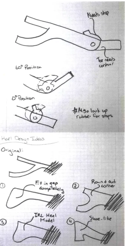
Improving upon the Concept Model mentioned in Section 5.1.1 and using the additional concept drawings as shown in Figure 14, this model as shown in Figure 15, referred to as the Shaft and Bearing Model, focused on making the system entirely passive. Similarly to the Concept Model, this model makes use of use of 2 parallel spring beams to provide a force to return the toe to 0' dorsiflexion and add some resistance to free rotation. In this design the joint rotation is limited between 0' and 60' by shaping a hollow pocket within the ball of foot area, shown in Figure 16.
In order to focus on converting to an entirely passive design the Shaft and Bearing Model used most of the same dimensions as the Concept Model. Additionally, similarly to the Concept Model, the load state of the toe and body were not taken into account.
NwrI
* ,
-i--Abe IWV. V
tR4L Hel
A~~~~~ eZkC ,o-~.
4
Figure 14: Sketches depicting ideation process for developing the design of the Shaft and
(a) (b)
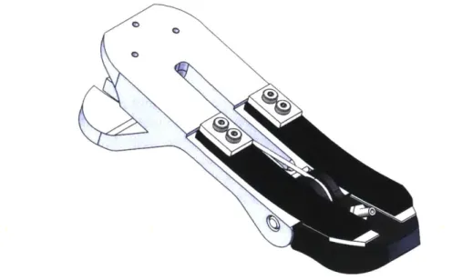
Figure 15: Solidworks CAD for the Shaft and Bearing Model based off the Concept Model
developed by Biomech. This design continues to use parallel spring beams similar to the Concept Model and features a shaft and bearing acting as the MTP joint. Panels (a) and (b)
(b) are side and isometric views to the model.
(a) (b)
Figure 16: A cross-sectional view of the Shaft and Bearing Model. The rotation is stopped by the hollow pocket within the ball of foot area such that the minimum and maximum
possible dorsiflexion angles are 0' and 60' in Panels (a) and (b) respectively. Intermediate angles are "controlled" by the returning force provided by the parallel spring beams (not shown).
After the CAD for the Shaft and Bearing Model was established, we 3D printed and assembled a physical model as shown in Figure 17 in order to observe how this design behaves in physical space.
Ago
Figure 17: Fully assembled model of the Shaft and Bearing Model based form the CAD
in Figure 15. This design features a toe and body made from 3D printed material, a shaft and bearing acting as the MTP joint, and 2 glass fiber parallel spring beams.
Printing a 3D model allowed us to realize several flaws with this design. First, since the load state was not considered, the toe, hinge, and body likely use an excessive amount of material. Secondly, the parallel spring beams would scratch the top surface of the toe when deflected. This could be solved by filleting the ends of the springs and adding some buffer material between the spring and the toe to avoid scratching, as shown in the Concept Model. We also considered replacing the parallel spring beams with torsional springs imbedded in the hinge, but ultimately decided against it as we did not have method to imbed torsion springs into the material of the toe or body. This option could be explored by researchers that move forward with these designs.
The protruding hood that was added to limit rotation to 600 would be problematic if the user decides to wear a shoe as most footwear is not designed to accommodate such large bulges near the toes. Finally, the hinge is rigid about its axis, which does not make this a very biomimetic design. If the user were to lean on the foot in the directions perpendicular to this design's axis of rotation, there would be little flexibility for them to do so - it does not handle eversion or inversion passively as a split foot design would.
Though a shaft and bearing seems to be the most intuitive method of creating a mechanical device with a wide angle of rotation, because of the issues discussed, we will consider methods of
4,
Using the equations from Section 3.3.2 we will also explore how to appropriately size the thickness of the material in the toe and body of the foot.
5.2 Flexural MTP Joints and Heel Designs
Since the focus of this thesis is on the MTP joint, we explored fewer alternatives to the geometry of the body. For changes to the body, besides altering the thickness, we explored geometries of the body's heel. One of the geometries we explored was inspired by many currently commercially available prosthetic feet like the LP Vari-Flex prosthetic foot [12]. We shall refer to the body that was developed that inspired this design as the Traditional Heel Body. We also explored a body geometry with a different type of heel design, as shall be soon discussed, that will be referred to as the Inverted Heel Body.
For the toe of the prosthesis (which will remain common between both body designs), we again took inspiration from the LP Vari-Flex prosthetic foot in order to account for the user leaning perpendicular to the MTP joint's axis of rotation. We also added slits down the center of most of the body to account for this as well. For the purposes of this thesis, we neglect the effect of removing this material from the cross sectional area since as explained earlier the effect of small decreases in width are essentially negligible.
After establishing the concepts and CAD models of the Traditional Heel Body and Inverted Heel Body, they were reused to explore alternate flexural MTP joint designs.
5.2.1 Rubber Hinge Design
We explored designing a flexural hinge made of rubber as shown in Figures 18-21. We chose to analyze this concept for a rubber material with type A hardness of 70 because that is standard in shoes which would be of practical importance if the user decides to not wear a shoe with the prosthesis. Similarly to the prior designs, this design makes use of 2 parallel spring beams to provide return force and resistance to free rotation.
As shown below, this type of hinge was developed for the Inverted Heel Body and Traditional Heel Body designs.
Inverted Heel Body Design:
r~ V.
Figure 18: Design notebook sketch of rubber hinge with the Inverted Heel Body design.
- 1 -1 -1n v e4e W&ae.,; t, -. row X= Ab-F144- a4,, K-ne P,-L,64L-+C,
U,.-ev-Figure 19: An isometric view of Solidworks CAD based off of the design sketches as
shown in Figure 18 using the Inverted Heel Body design with a rubber hinge.
Traditional Heel Body Design:
Figure 20: Design notebook sketch of the Rubber Hinge with the Traditional Heel Body
Figure 21: An isometric view of Solidworks CAD based off of the design as shown in
Figure 20 using the Traditional Heel Body design with a rubber hinge.
5.2.2 Fabric Hinge Design
We also chose to explore the design of a hinge made from reinforced fabric as shown in Figures 22-24. The 00 to 600 dorsiflexion angle is bounded by the tension in the fabric preventing the toe from rotating below 0' and by the edges of the clamps securing the fabric shaped such that the angle between them sums to 60'. This design still makes use of the parallel spring beam, however, unlike the other models discussed, it utilizes one wider spring beam to accommodate the space needed for the clamps securing the fabric hinge.
As shown in Figures 22-24, this type of hinge was developed for the Inverted Heel Body and Traditional Heel Body designs.
Inverted Heel Body Design:
04
Figure 22: Design notebook sketch of fabric hinge concept including top and side views.
While considering this design, we had to rethink the placement of the parallel spring beams since the clamps to fasten the fabric in the hinge would occupy the springs' former space. This led us to alter the geometry of the spring beam to be one wider beam, rather than the dual beams in previous designs.
Figure 23: Solidworks CAD based off of the design sketches as shown in Figure 22 using the Inverted Heel Body design.
Traditional Heel Body Design:
Figure 24: Solidworks CAD based off of the design sketches as shown in Figure 22 and
adapted from the Inverted Heel Body design in order to use the Traditional Heel Body design.
5.3 Finite Element Analysis
components of interest in each design. This resulted in the Toe, Inverted Heel Body, and Traditional Heel Body. Each component was placed in their worst-case scenarios of static loading at 60' dorsiflexion which will be discussed further in the following sections.
Though we could have substituted many other materials, as shown in Section 6.2, for the FEA we used a glass fiber by Gordon Composites (the same material as the parallel spring beam) as an example material of choice since its relatively low stiffness (compared to metals) yet high yield strength are ideal qualities for the type of material we would realistically implement for a human user.
5.3.1 Toe
The Toe was loaded as if the user was standing on tiptoe, as shown in Figure 4, with 60' dorsiflexion for each design. We fixed the face of the Toe adjacent to the MTP joint and applied a load of 2076 N (calculated based off Equation 7 for the Toe) on the face of the Toe facing the ground in the direction normal to the bottom face of the Toe to emulate effect of the reaction force from standing on the ground as shown in Figure 25. Since we are assuming the worst-case scenario for the Toe, it is fair to use this load state since there would be no load placed on the body of the foot.
(a) (b)
(c) (d)
Figure 25: Loaded state of the Toe with force predicted at 600 dorsiflexion. Panels (a) and (b) are the toe used in the Rubber Hinge design and Panels (c) and (d) are for the Fabric
Hinge design. The major difference in the geometry of these parts is the section of the component that interfaces with the hinge.
5.3.2 Traditional Heel Body
The Traditional Heel Body was loaded as if the user was standing with all their weight on the
heel. We fixed the face of that would be interfacing with the ankle prosthesis and applied a load
the ground in the direction normal to the bottom face of the Traditional Heel Body to emulate effect of the reaction force from standing on the ground as shown in Figure 26.
(a)
(c)
(b)
(d)
Figure 26: Loaded state of the Traditional Heel Body with force predicted for standing with all weight on the heel. Panels (a) and (b) are the Traditional Heel Body used in the Rubber Hinge design and Panels (c) and (d) are for the Fabric Hinge design. The major difference in the geometry of these parts is the section of the component that interfaces with the hinge.
5.3.3 Inverted Heel Body
The Inverted Heel Body was loaded as if the user was standing with all their weight on the heel, similarly to the Traditional Heel Body. We fixed the face of that would be interfacing with the ankle prosthesis and applied a load of 800.68 N (approximate average weight of an American adult male) on the face of heel facing the ground in the direction normal to the bottom face of the Inverted Heel Body to emulate effect of the reaction force from standing on the ground as shown in Figure 27.
(a)
(c)
(b)
(d)
Figure 27: Loaded state of the Inverted Heel Body with force predicted for standing with
all weight on the heel. Panels (a) and (b) are the Inverted Heel Body used in the Rubber Hinge design and Panels (c) and (d) are for the Fabric Hinge design. The major difference in the geometry of these parts is the section of the component that interfaces with the hinge.
6. Results and Discussion
6.1 Young's Modulus of Parallel Spring Beams
We sought to confirm the Young's Modulus for the glass fiber material by Gordon Composites used by the parallel spring beams. We performed a 3-point flexure test as discussed in Section 3.2
by subjecting a sample of the material with dimensions L = 120.1 mm, b = 15.09 mm, and
h = 3.30 mm as shown in Figure 7 to a vertical load perpendicular to the cross-sectional area for
an incrementing range of forces with the Instron machine up to 1000 N. We measured the deflection of the beam's midpoint with respect to the zero load condition. We also measured the machine compliance of the Instron universal testing machine applying load against itself up to 1200 N as shown in Figure 9 and measured the deflection due to this applied load. We obtained data for both deflections from the Instron universal testing machine as shown in Figure 28.
By knowing the deflection of the beam's midpoint and the deflection due to the machine's
compliance, we can use Equation 3 to find 6Rea,, then rearrange Equation 1 to determine the
Young's Modulus by substituting 4Rea1 for 8.
1200 1000 0 -J 800 600 400 200 0 0 1 2 3 Deflection [mm] 4 5
Figure 28: Data from the 3-point flexure test for the spring beam collected from the Instron
universal testing machine. The points in red represent the deflection of the mid-span of the spring beam as a result of loading from 0 N to 1000 N whereas the points in blue represent the deflection of the machine due to applying a load to itself when loaded up 1200 N.
* [ ahine| 6 * S 0 *
0-We determined with 95% confidence that the Young's Modulus of the parallel spring beam was 38.6 3.40 GPa, which was quite close to the manufacturer's material data sheet's value of 40 GPa.
6.2 Determining Appropriate Material Thickness
Since we also know Equation 4, we can derive the expression
F =TMTP (7)
r
where r is the lever arm distance from the MTP joint. By utilizing Equation 5 and substituting A = bh. We define a criteria for yield stress such that for any material with the property
Uy !'MTP
ry rbh
qualifies as a valid material to use at a particular height
5 10 Material Thickness [mm] 15 60 (L 50 (A ca40 0 A= . 0* Cr m 20 a: V 10 0 (8)
while sustaining adequate loads.
--Bod 0 (a) 5 10 Material Thickness [mm] 15 (b)
Figure 29: Result of expression in Equation 8. The line in each plot represents the
minimum allowable yield stress a material could have if that particular thickness is to be used. Panel (a) represents the criteria for the toe segment of the prosthesis while Panel (b) represents the criteria for the body segment of the prosthesis. This result confirmed that there is a wide range of options for what materials could be used in this application. Future designers can adjust dimensions and check if they need to adjust material usage as a result.
6.3 Finite Element Analysis
We used the Solidworks Simulation FEA Tool on the Toe, Inverted Heel Body, and Traditional Heel Body for each design. As an example material, we used a glass fiber by Gordon Composites (the same material as the parallel spring beam). The results of the simulation yielded that none of
140 -Toe 0 CL 120 100 60 60 40 20 0 0
the models under the worst-case scenarios had any plastic deformation or fracture throughout the von Mises stress distribution.
We'll define the von Mises safety factor Sf as:
(9)
where cy represents the yield stress and a represents the working stress, which in our scenario is the von Mises stress distribution at a particular point. We display in the following figures these stress distributions of our components of interest.
6.3.1 FEA Results of the Components from the Rubber Hinge Design
The stress distribution with a magnified deformed result under the worst-case scenario loading as defined above is shown in Figure 30. For each component, the maximum von Mises stress does not exceed the yield stress of the given material and have a minimum safety factor of 5.7, 10, and
4.5 for the Toe, Inverted Heel Body, and Traditional Heel Body respectively. These high safety factors imply that though the design did not undergo failure under the prescribed loads, material utilization was in excess and could be further optimized to decrease the weight.
Model name Top I SlUdynatio scal S.090M l
Plot type: Stak nod., slress Sits I
Defonnatieo "V11 &MMI6 5 Yieki sIOr'nth 1 050 r (a) vor Miu- (Nrrn) I 1.85se'Slr 1.7ODr+0M I 546e.(XS 1.391e+-"r 1.237e+01 1.092P +001 9275r+00i 7.729P-00j' 6.183e*-00i 4.637P+00, 3.092e+00i 1.546e+00i 2.066e-001 Sf =
-Model amreInwetted Heell
Study name Irwerted Heel Rubber Hinge Study(-Nefauk-) Plot type Stalk nmd stress Stress'
Deformation scale: 9 36349
A
? tt
' M65b 2!/ .-O
(b)
Model name Tradbonal Heel
Sudy nane:1adkional Heel Rubtwr Hoge Studyl Defmilt
Plot type 51i* nodi Stress StressI Deormation scale I I Mm: 7 592e+00 win M ies (N/m^l) 1.038e-006 9 517e007 &652e+007 7.787e.007 6.92le-007 6.056ie+0D7 5,191e+007 4326e -001 1461e 007 2.596e-00/ 1 ?30e.+o)/ &652P -006 S.691e+00 b Yied stremth 1 OO t009
von Mets (N/m^/I)
2314e-00t 1 928. -(R 1.735e -Ot0' 1.542e -" 1350. -0(1 9.641e-rOr 9.9e -001 1 92e . 0/ 7 .9e -10 / b Yiek tnth l M-OuS.iO (c)
Figure 30: Solidworks FEA results showing the magnified deformed state of the for the Toe, Inverted Heel Body, and Traditional Heel Body components in Panels (a), (b), and (c) respectively after the load was applied for the Rubber Hinge design. The red-to-blue color bar represents the stress distribution throughout the component where red represents the highest stresses and blue represents the lowest stresses.
6.3.2 FEA Results of the Components from the Fabric Hinge Design
The stress distribution with a magnified deformed result under the worst-case scenario loading as defined above is sown in Figure 31. For each component, the maximum von Mises stress does not exceed the yield stress of the given material and have a minimum safety factor 1.4, 9.9 and 4.5
for the Toe, Inverted Heel Body, and Traditional Heel Body respectively. Similar to the components in the Rubber Hinge design, these high safety factors imply that though the design did not undergo failure under the prescribed loads, material utilization was in excess and could be further optimized to decrease the weight.
For the Toe, the maximum stress moved from the edge of the Toe to the holes allowing for the fabric to be held down by the clamps. The safety factor of the Toe decreased drastically from the Rubber Hinge Design.
For the Inverted Heel Body and Traditional Heel Body, the location of maximum stress seems to remain in the same area. The safety factor for the Inverted Heel Body decreased slightly and the safety factor for the Traditional Heel Body remain the same compared to the FEA results for the components in the Rubber Hinge design.
Model namwToe2 Study nanw To@2Shoy( Defalt) Plot t Saw nodad stres S 1ul
Defonnaton scale 1 von Mises (N/m^2 7313e -06 I674eCt 4- 64e-om iSAe-009 -1657r+OM Llt- Bbe 004 047e-OM 293e-OW I 19e -006 465e -004 (a)
ModeI vsn Insvrld Hes4?
Study iwnt nestled Heel labos Hvge Study( Deault
Plot ".p SUMt no" strew Stress'
Defonnatian scale 101449 Max 10 nMs'(N/ 9.715P -00/1 .7.9w.e00/ 7.065e 007 &182e+001 5-3990-00/ 4416P-0/ 85331 -O0/ 3139P.001 1.766e-00/ 5.831e +(XM
b Ste strmatir 1.fOio+ W9
Model nanrwTradilional Hee@
SW* naneradmonal Heel Fabi tfeqe Suidyl Defaua) Plot "yp SOA roD" suest Sljeos
De~oomation scale: I Van MiseS (Nm^2) 2 353e-OW 121571+OOB 1.765r'O1 1.569e0 1 373rlXI 1. 1 Te' 007 9.805e, ON 7.844e.W7 3.922P+00/ 1.%1e'001 905e.00i -Yrktlsrongth 1(0S(r -OM9 (c)
Figure 31: Solidworks FEA results showing the magnified deformed state of the for the Toe, Inverted Heel Body, and Traditional Heel Body components in Panels (a), (b), and (c) respectively component after the load was applied for the Fabric Hinge Design. The red-to-blue color bar represents the stress distribution throughout the component where red represents the highest stresses and blue represents the lowest stresses.
-7. Conclusions and Future Work
We began our iterative design process with the Concept Model, originally developed by Biomech, and developed the Shaft and Bearing Model, which we fabricated and assembled. We evaluated what features could be changed or improved so that we could develop a platform more suitable for a human user.
We then iterated through various ideas as shown in the figures from Section 5 and 8. From what we learned from interacting with the Shaft and Bearing Model, we developed a total of 4 models to test with the Solidworks Simulation FEA Tool. These 4 models consisted of 2 designs for the body, the Traditional Heel Body and Inverted Heel Body and 2 designs for flexural MTP joints, the Rubber Hinge and Fabric Hinge. For the Rubber Hinge and Fabric Hinge designs, we placed the Toe, Inverted Heel Body, and Traditional Heel Body in their worst-case scenarios of static loading at 600 dorsiflexion, standing on tiptoe for the toe components and standing with all weight on the heel for the body components.
The FEA results yielded that not only do none of the components yield under the expected load, but there are also considerable safety factors. The Fabric Hinge design has a lower safety factor than the Rubber Hinge design making the Rubber Hinge a more inefficient design in terms of material utilization. These high safety factors imply that though the design did not undergo failure under the prescribed loads, material utilization was in excess and could be further optimized to decrease the mass of the prosthesis.
The author suggests that future work should begin with fabricating a 3D printed physical model of the Rubber Hinge and Fabric Hinge designs, observe how they behave in a physical space, and evaluate the advantages and disadvantages of each design similar to how we did so for the Shaft and Bearing Model. Though simulation can provide a lot of useful information, observing a physical model could help deepen our understanding of how this design will perform for a human user.
The next step would be to research the dynamic loading that would be typical of normal gait and simulate the scenario using FEA simulation. The author also recommends simulating the static and dynamic loading scenarios with multiple other materials that fit the criteria developed in Section 6.2.
The models discussed in this thesis were developed with 3D printing in mind as the fabrication method. However, 3D printing of composite materials is rather limited and not practical for large-scale production. Modifications to the design of the models discussed would be needed in order to test a high fidelity physical model. While modifying the design, decreasing the safety factor and optimizing material utilization should remain a priority. After such
modifications are made, the author recommends simulating the CAD model of the modified design using FEA and then testing a physical model under the same loading conditions to compare the accuracy of the results.
Finally, the author considered other designs that could potentially be useful to future researchers but were not fully explored due to the scope of this thesis. These concepts were sketched in Section 8 and should be explored in depth similarly to the Rubber Hinge and Fabric Hinge designs. This thesis also limited exploring other geometries of the body component of the prosthesis, which should also be considered in greater detail.
8. Appendix: Other Design Concepts Considered But Not Fully Explored bLA4alc 'I v ~ i~LJ~ ~ 0 0 0 ~44 '-p ~L' H44eL kt~4r.6I~.A~& ot49 %2t' V J
Figure 32: Sketches of ideas to alternative shaft and bearing hinges for the MTP joint,
iterating on Shaft and Bearing Model. We also explored different geometries for the toe component.
... I I ~Lr.7'
Hollow-V r F2.. ®R 7phr mt4Lw V ' O 103.'8 e"~ L
6~u
C&~. tqFigure 33: Sketches of ideas to develop a prosthetic foot with a living hinge acting as the
MTP joint. We explored different geometries for the living hinge as well as different body shapes. Living hinges are typically made of a thin strip of the material of the pieces that are moving around it similar to the plastic caps found on many consumer products such as shampoo or condiment bottles. There are also living hinges such as the ones featured that are made from thicker material but cutout some of that material to decrease the stresses due to placing the material in bending. This idea was inspired by the kinds of living hinges in pieces of wood with laser cut slits to create patterns to allow for bending. Living hinges differ from traditional hinges like the one in the Shaft and Bearing Model or door hinges
by utilizing their own material to allow for rotation, rather than relying on multiple parts
0DOF (..4
Figure 34: Sketches of ideas to develop a prosthetic foot with 2 joints, the MTP joint and
the talus joint. We developed a sketch model of this design and found that when the device is moving to complete a step, all the joint rotation is done by the talus instead of the MTP joint, pushing the prosthesis to be flat of the ground from the talus to the toe. This would
have led to motion that is not typical to normal gait.
tar
R&r
.... v ~*4~ ~(~-N wat~~, IN
a
9. References
[1] Rawlinson, A. L. C., 2016, "Caulfield Prosthetics from 1915 to 2015," ABC News [Online].
Available:
https://www.abc.net.au/news/2016-04-21/caulfield-prosthetics-from-1915/7343002. [Accessed: 07-May-2019].
[2] Herr, H., Prosthetic Legs MIT Media Lab Biomechatronics Group.
[3] Ziegler-Graham, K., MacKenzie, E. J., Ephraim, P. L., Travison, T. G., and Brookmeyer, R., 2008, "Estimating the Prevalence of Limb Loss in the United States: 2005 to 2050," Arch.
Phys. Med. Rehabil., 89(3), pp. 422-429.
[4] Man, H.-S., Leung, A. K.-L., Cheung, J. T.-M., and Sterzing, T., 2016, "Reliability of Metatarsophalangeal and Ankle Joint Torque Measurements by an Innovative Device," Gait Posture, 48, pp. 189-193.
[5] "Hallux Rigidus (Stiff Big Toe) -HSS.Edu," Hosp. Spec. Surg. [Online]. Available:
https://www.hss.edu/condition-list-hallux-rigidus-stiff-big-toe.asp. [Accessed:
09-May-2019].
[6] Gailey, R., 2008, "Review of Secondary Physical Conditions Associated with Lower-Limb
Amputation and Long-Term Prosthesis Use," J. Rehabil. Res. Dev., 45(1), pp. 15-30.
[7] Au, S. K., Weber, J., and Herr, H., 2009, "Powered Ankle--Foot Prosthesis Improves
Walking Metabolic Economy," IEEE Trans. Robot., 25(1), pp. 51-66.
[8] Bateni, H., and Olney, S. J., 2004, "Effect of the Weight of Prosthetic Components on the
Gait of Transtibial Amputees," J. Prosthet. Orthot., 16(4), pp. 113-120.
[9] Hawes, M. R., and Sovak, D., 1994, "Quantitative Morphology of the Human Foot in a
North American Population," Ergonomics, 37(7), pp. 1213-1226.
[10] Rao, S., Song, J., Kraszewski, A., Backus, S., Ellis, S. J., Md, J. T. D., and Hillstrom, H. J., 2011, "The Effect of Foot Structure on 1st Metatarsophalangeal Joint Flexibility and
Hallucal Loading," Gait Posture, 34(1), pp. 131-137.
[11] "13 Outline Drawing Foot for Free Download on Ayoqq.Org," Ayoqq.org [Online]. Available: https://ayoqq.org/explore/outline-drawing-foot/. [Accessed: 16-May-2019]. [12] "LP Var-Flex" [Online]. Available:
![Figure 2: Various modem ankle-foot prostheses developed by the MIT Media Lab Biomechatronics Group [2].](https://thumb-eu.123doks.com/thumbv2/123doknet/14678921.558738/9.917.106.808.116.424/figure-various-modem-prostheses-developed-media-biomechatronics-group.webp)
![Figure 3: Visual representation of the anatomical location of the MTP joint in a human foot relative to other critical structures [5].](https://thumb-eu.123doks.com/thumbv2/123doknet/14678921.558738/10.917.139.730.110.447/figure-visual-representation-anatomical-location-relative-critical-structures.webp)

![Figure 6: A schematic representation of the 4 proportional sections of the foot in relation to each other [11]](https://thumb-eu.123doks.com/thumbv2/123doknet/14678921.558738/15.917.183.701.196.480/figure-schematic-representation-proportional-sections-foot-relation.webp)


![Figure 11: Visual representation of the overall dimensions of the comparable device, the LP Vari-Flex prosthetic foot by Ossur [12].](https://thumb-eu.123doks.com/thumbv2/123doknet/14678921.558738/19.917.153.689.120.413/figure-visual-representation-overall-dimensions-comparable-device-prosthetic.webp)