Design of a Screenless Hammermill
by
Amy B. Smith
Submitted to the Department of Mechanical Engineering
in partial fuilfillment of the requirements for the degrees of
Mechanical Engineer
and
Master of Science in Mechanical Engineering
at the
MASSACHUSETTS INSTITUTE OF TECHNOLOGY
May 1995
©
Massachusetts Institute of Technology 1995. All rights reserved.
.* : ACH;i-So'- r INST;-i U'ie OF TECHNOLOGY
MAR 91996 '
LIBRARIES
Author
...
Amy B. Smith
Department of Mechanical Engineering
,
/7)
-a
v 12,
1995
Certified
by
...
,...
-.
Carl R. Peterson
Professor of Mechanical Engineering
-*ft
Supervisor
Accepted by.
.. A... Sonin. .Ain A. Sonin
Design of a Screenless Hammermill
by
Amy B. Smith
Submitted to the Department of Mechanical Engineering
on May 12, 1995, in partial fulfillment of the
requirements for the degrees of Mechanical Engineer
and
Master of Science in Mechanical Engineering
Abstract
A screenless hammermill which uses aerodynamic separation rather than a perforated screen to separate flour from unground grain was designed for grinding grain in de-veloping countries. It was found that the circumferential and radial position of the flour outlet on the frontplate of the mill were important factors in determining the throughput of the mill and the quality of the flour produced. Placing the flour outlet
at a position 40° from vertical in the direction of rotation of the blades at a distance
of about two-thirds of the radius of the grinding chamber yielded high quality flour at a throughput that is comparable to conventional hammermills. A prototype was built and tested at the Sodefitex Cereal Transformation Facility in Tambacounda, Sene-gal. The quality of the flour produced by the screenless hammermill was evaluated by sifting and weighing the fractions containing particles greater than 1 millimeter, between 0.6 and 1 millimeters, and less than 0.6 millimeters. The particle size dis-tribution was equal to or superior to flour produced by conventional hammermills. The flour was also evaluated subjectively by the Sodefitex staff and was found to be superior to that produced by a conventional hammermill. The screenless mill can be manufactured by a village artisan for about $520, or approximately one quarter the cost of a conventional hammermill. It uses up to seventy percent less energy to operate, making it a promising new technology for rural grain processing.
Thesis Supervisor: Carl R. Peterson
Acknowledgments
As I was preparing the estimates of the milling costs and converting the price from
CFA to dollars, I realized how little the milling fees were, and yet; how few women
can afford them. This research is dedicated to the African women who cannot afford the 5 cents it takes to mill a kilogram of flour and thus spend hours performing the back-breaking labor necessary to prepare food for their families. I would also like to acknowledge the others who have dedicated themselves to improving the lives of these women, in particular Carl Bielenberg and Cheikh Gueye of ATI, without whom this work would not have been possible. Grateful appreciation to Professor Carl Peterson and, as always, to my friends and family for their love and support.
Contents
1 Introduction 7
2 Background 10
2.1 Rural Development in Africa ... 10
2.2 Grain Processing Technologies . . . .. . 14
2.3 Development of the Screenless Hammermill ... 16
3 Design 20 3.1 Analysis of the 2.72 Mill ... 20
3.2 Design of the Flour Collection Apparatus . ... 21
3.2.1 Outlet Length ... 22
3.2.2 Radial and Angular Position ... 23
3.2.3 Optimizing the Operation Cycle ... 28
4 Field Testing of the Screenless Hammermill 30 5 Conclusion and Recommendations 38 A Materials Lists 43 B Final Engineering Drawings 46
List of Figures
1-1 The Conventional Hammermill ... 8
1-2 The Screenless Hammermill ... 9
2-1 Traditional Milling . . . ... 12
2-2 A Conventional Hammermill ... 13
2-3 The Interior of the Bielenberg Prototype Screenless Hammermill . . . 17
2-4 The 2.72 Prototype Screenless Hammermill ... 19
3-1 Cross-section of the 2.72 Prototype ... 21
3-2 Cross-section of the 2.72 Prototype ... 22
3-3 Prototype Mill for Testing the Effect of the Radial and Angular Posi-tion of the Flour Outlet on the Flour Quality and the % Flour Reclaimed. 24 3-4 Effect of Angular and Radial Position on % Flour Reclaimed ... 25
3-5 Effect of Angular and Radial Position on Flour Quality ... 26
3-6 The Optimal Position of the Flour Outlet ... 27
4-1 Prototype of the Mill Built in Senegal ... 34
5-1 The Amtech Screenless Hammermill ... 39
List of Tables
2.1 Test Results For The 2.72 Mill ... 18
3.1 Effects of Outlet Length on Flour Quality and % Flour Reclaimed . . 23
3.2 The Effect of Sealing the Inlet on Percent of Flour Reclaimed ... . 28
3.3 The Effect of Sealing the Flour Outlet on Percent of Flour Reclaimed for Three Minute Runs ... 28
4.1 Test Results For The ATI Mill ... 31
4.2 Test Results For Determining The Outlet Position Of The Retrofit ATI Mill ... 31
4.3 Test Results For The Retrofit ATI Mill ... 32
4.4 Test Results For The Amtech Mill ... . 35
4.5 Estimated Milling Costs ... 37
A.1 Materials List for the Screenless Hammermill ... 44
A.2 Materials List for a Conventional Hammermill ... 45
Chapter 1
Introduction
Grinding grain into flour is one of the most labor-intensive tasks performed by women in rural areas of developing countries. It takes about 30 minutes to grind a kilogram of flour by hand, but less than seventy seconds when using a conventional hammermill. It is no surprise therefore that mills are one of the most frequently requested items by women's groups in developing countries. Existing milling technologies, however, often fall short of the women's expectations. Several components must be imported and require frequent replacement, which increases milling costs and requires continued maintenance. The goal of this project is to adapt an existing milling technology, the hammermill, so that it is more appropriate for use in rural areas of developing countries.
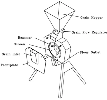
Conventional hammermills, shown in Figure 1-1, have rotating hammers which grind the grain in a grinding chamber and a perforated steel screen which separates the flour from the larger, unground particles. The flour particles are carried through the screen by their centripetal momentum and the larger particles remain inside the chamber. The screens are the most fragile component of the mill; they cannot be produced locally and they are expensive to replace. Furthermore, the screen often gets clogged and the mill must be stopped and the screen cleaned out. In order to make a hammermill which is better suited for rural areas of developing countries, it should be designed to operate without a screen. To further reduce milling fees, the mill should be designed to minimize the manufacturing and operating costs.
in Hopper Ha: Scree Grain Inlet Frontplate )w Regulator Lr Outlet
Figure 1-1: The Conventional Hammermill
It is possible to separate flour from unground grain without using a screen by taking advantage of the differences in the aerodynamic properties of the particles. By placing the flour outlet in a suitable location, as shown in Figure 1-2 aerodynamic separation can be achieved. The fine particles are carried out of the mill by the airflow through the outlet and the larger particles remain at the periphery of the mill, as the velocity of the airstream at the position of the flour outlet is not sufficient to divert their motion and carry them out. Further improvements to the mill include a single hammer blade which is directly mounted to the motor shaft and a grits discharge which allows continuous operation of the mill. These improvements allow the mill to be produced at about a quarter of the cost of conventional hammermills. In addition, the energy consumption to operate the mill is decreased by about seventy percent and a superior product is produced.
. Outlet
its Discharge
Chapter 2
Background
2.1 Rural Development in Africa
Since the early 1970's, rural development strategies in African countries have un-dergone two major shifts. The first shift concerns the beneficiaries of international development aid packages. It was found that although millions of dollars of aid money were going into rural development, hunger persisted and there was not a marked in-crease in the production of subsistence crops. After some re-evaluation it became apparent that this was partly because most of the aid was going to men's farming groups, which primarily grew cash crops. Almost all of the subsistence crops were
grown by women. A number of donor organizations have since started to focus their
efforts on assisting rural women. Two activities in particular, which are among the most labor-intensive, have been targeted as areas where aid should be directed- water acquisition and grain processing. In fact, pumps and mills are the most-commonly requested items by rural women's groups.
The other major shift in rural development strategies has been to steer away from "high-tech" solutions to problems and to look for intermediate technologies or appropriate technologies. This idea was presented by Ernst Schumacher in his book Small is Beautiful in 1973 and has been accepted by many donor organizations, such as Appropriate Technology International (ATI) and the Intermediate Technology
Schumacher defines intermediate technologies in terms of the cost of the technology [7]. Indigenous technologies are of the order of $10 per workplace while imported technologies are typically more than $1000 per workplace. There exists a gap, in the $100 range, which can be filled by intermediate technology. Intermediate technologies are more productive than indigenous technologies, but cost significantly less than advanced technologies. In the case of grain milling in rural Africa, the indigenous technology is the mortar and pestle, shown in Figure 2-1; the advanced technology is the conventional mill, shown in Figure 2-2. There is thus a niche for a low cost mill which produces flour at a faster rate than hand grinding but at a lower cost than conventional mills. The concept of intermediate technologies deals not only with hardware, but also with the technical expertise and organizational skills required to use and produce it.
The idea of intermediate technology led to a new field known as appropriate technology. Appropriate technologies deal not only with the scale and cost of the technology, but also consider the use of local resources and the cultural issues which lead to the acceptance of a technology. While there is not a single definition for what constitutes an intermediate, or appropriate, technology; the following guidelines have been set out by Ken Darrow and Rick Pam in the Appropriate Technology Sourcebook [3].
Appropriate technologies: * are low in capital costs,
* use local materials whenever possible, * create jobs, employing local skills and labor,
* are small enough in scale to be affordable by a small group of farmers,
* can be understood, controlled and maintained by villagers wherever possible, without a high level of Western-style education,
* suppose that people can and will work together to collectively bring improve-ments to their communities, recognizing that in most of the world important decisions are made by groups rather than by individuals,
* involve decentralized renewable energy sources such as wind power, solar energy, water power, methane gas, animal power and pedal power,
* make technology understandable to the people who are using it and thus suggest ideas that could be used in further innovations,
* are flexible so that they can continue to be used or adapted to fit changing circumstances,
* do not involve patents, royalties, consultant fees, import duties, shipping charges, or financial wizards; practical plans can be obtained free or at low cost and no further payment is involved.
It must be stressed that an appropriate technology is one that provides as many jobs as possible especially in labor-rich areas. This does not mean that appropriate
technologies can only exist in labor-intensive industries, but it does mean that the creation of jobs should be maximized. The introduction of an advanced technology often leads to the decline of indigenous technologies faster than it provides jobs. An intermediate technology can provide increased productivity yet still allow numerous workplaces to be established, thus allowing a larger number of people to benefit from the technology.
2.2 Grain Processing Technologies
Processing grain is one of the most labour-intensive processes in rural Africa. After the grain has been harvested, it must be threshed to remove the grains from the stalk. This is traditionally done by placing the stalks on the ground and beating them with a stick to loosen the grains. Sometimes livestock are used to trample the stalks to remove the grain. Dirt and other contaminants are removed by winnowing, (shaking
and tossing the grain and allowing the wind to remove the unwanted particles), then the grain is allowed to dry. Once dried, the grain is dehulled using a mortar and pestle to loosen the coarse outer covering of the grain then winnowed to remove the hulls and then finally it can be ground to produce flour or meal.
Traditional milling is done with a mortar and pestle and produces about 2 kilo-grams of flour in an hour. Hand operated mills produce flour at a higher rate, but are rarely considered to be worth the investment, as they involve almost as much labor as traditional milling and are more expensive. Mechanized mills can produce over 100 kilograms of flour per hour and are thus one of the most frequently requested items by women's groups in developing countries. There are three main types of mills currently available- roller mills, plate mills and hammermills- but none of these has been shown to be clearly superior for use in rural areas.
Roller mills compress and shear the grain between two rollers, with the distance between the rollers determining the fineness of the flour produced. There are typically
several sets of rollers, each of which produces increasingly fine flour. The rollers
must be precisely machined and their alignment is critical, which makes these mills expensive and difficult to maintain.
Plate mills grind the grain between two abrasive grinding plates, one rotating and one stationary. As with the roller mill, the distance between the plates determines the fineness of the flour. In some cases, the grain must be passed through the mill twice to achieve the desired fineness. Plate mills are relatively easy to maintain, but the grinding plates wear out and replacements must be imported, which adds significantly to the cost of the mill.
Hammermills have high speed rotating blades which grind the grain in a grinding chamber. The flour is separated from the larger particles by a screen which allows the flour to be carried out by the airflow through the mill while keeping the larger particles inside the chamber. The flour is collected in a cloth bag which is placed over the outlet, allowing the air to pass through the cloth while the flour particles remain inside. Under normal operating conditions hammermills are very robust, however stones or coins may be mixed in with the grain and can damage the screen. A typical
mill uses up to eight screens in a year. The screens cannot be produced locally and they are expensive to replace. The screen often gets clogged by the residual bran and the mill must be stopped and the screen cleaned out. Hammermills are preferred in some regions because they can produce flour from wet grain which has begun to ferment and thus gives the desired flavor [4].
In order for any of these technologies to be suitable for rural areas, they must be redesigned to obviate the need for expensive imported parts which require frequent replacement. The rollers and grinding plates are critical to the functionality of the mill, and currently available manufacturing techniques in developing countries do not allow them to be made locally. The screen of a hammermill is not used to grind the grain, but rather to collect the final product. The hammermill could be redesigned to use a different collection process, allowing it to operate without the delicate, expensive screens.
2.3 Development of the Screenless Hammermill
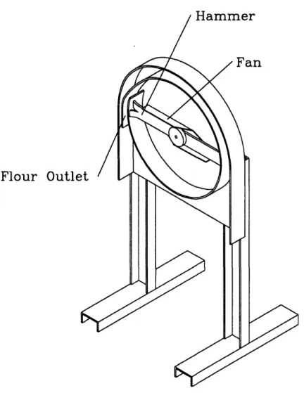
Carl Bielenberg of Appropriate Technology International (ATI) first began to work on a screenless hammermill in 1990. He produced a prototype which separated the flour from the larger particles, or grits, through an opening in the circumference of the grinding chamber, as shown in Figure 2-3. Flour passed through the opening in the opposite direction from the rotation of the hammer blades, and the larger parti-cles, having greater momentum, continued forward and remained inside the chamber. Initial tests showed that the mill could grind about 90 kilograms of maize per hour, however the flour was very coarse; almost half of the flour was made up of particles greater than 0.6 millimeters in size. Conventional hammermills produce flour in which less than thirty percent (by weight) of the particles are greater than 0.6 millimeters. In order to improve the flour quality, the overlap of the chamber walls at the flour outlet was increased. Although this did improve the quality of the flour, the through-put was decreased. In addition, the outlet clogged easily and the mill could not be run continuously [2].
Fan
Flour Outle
Figure 2-3: The Interior of the Bielenberg Prototype Screenless Hammermill
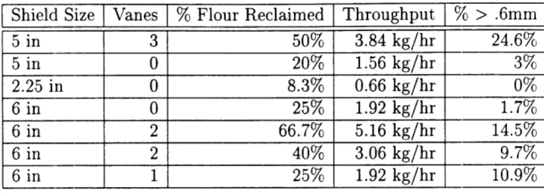
[Shield Size Vanes % Flour Reclaimed Throughput % > .6mm 5 in 3 50% 3.84 kg/hr 24.6% 5 in 0 20% 1.56 kg/hr 3% 2.25 in 0 8.3% 0.66 kg/hr 0% 6 in 0 25% 1.92 kg/hr 1.7% 6 in 2 66.7% 5.16 kg/hr 14.5% 6 in 2 40% 3.06 kg/hr 9.7% 6 in 1 25% 1.92 kg/hr 10.9%
Table 2.1: Test Results For The 2.72 Mill
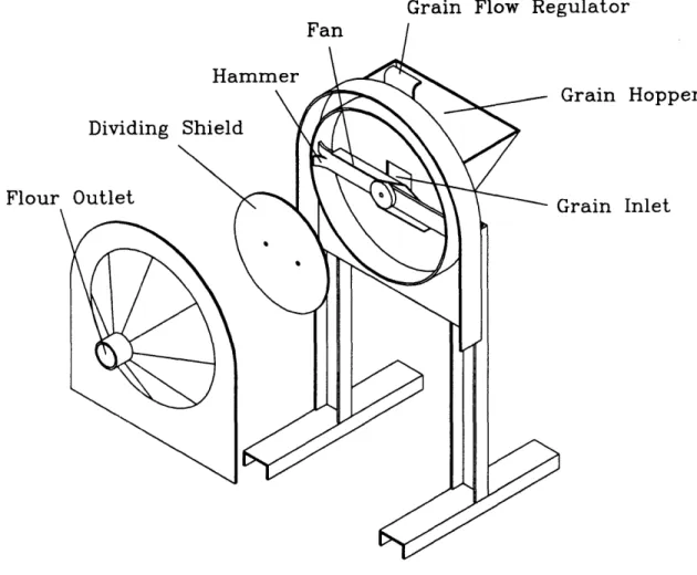
Encouraged by the promising initial results, Bielenberg brought the project to MIT where a group of students in the 2.72 Elements of Mechanical Design class took over the project and introduced a secondary chamber to separate the flour, as shown
in Figure 2-4.
Tests were performed varying the size of the dividing shield, the shape of the separation chamber and the number of vanes in the chamber. One and a half pound (0.45 kilogram) samples of corn were ground for three and a half minutes and the
flour was collected and weighed. In all cases a significant amount of grain remained
in the mill- only a limited amount was reclaimed as flour. The results are shown in
Table 2.1.
It was found that a conical separation chamber improved the recirculation of the
larger particles back into the grinding chamber, giving a higher throughput. The
size of the dividing shield determined the gap between the chamber wall and the dividing shield. As the gap increased, the airflow through the mill increased and the throughput increased, but the flour quality decreased. The vanes also increased the airflow through the mill and had a similar effect of increasing the throughput while decreasing flour quality [1]. While the clogging problem was eliminated the by the introduction of the separating chamber and the overall flour quality was good, the throughput was drastically decreased. In order for this technology to be successful, it was necessary to redesign the collection process so that a high throughput was achieved without sacrificing flour quality.
Grain Flow Regulator
Grain Hopper
Grain Inlet
Figure 2-4: The 2.72 Prototype Screenless Hammermill
Flour
Chapter 3
Design
The main objective of this project was to improve the performance of the screenless hammermill by increasing the throughput and the percentage of flour reclaimed while maintaining flour quality. The redesigned mill was required to run continuously with-out clogging and be simple to manufacture and maintain. Furthermore, it could not be dependent on tight tolerances or special material properties for its performance, as it must be easily manufactured in a small village-level metal workshop.
3.1 Analysis of the 2.72 Mill
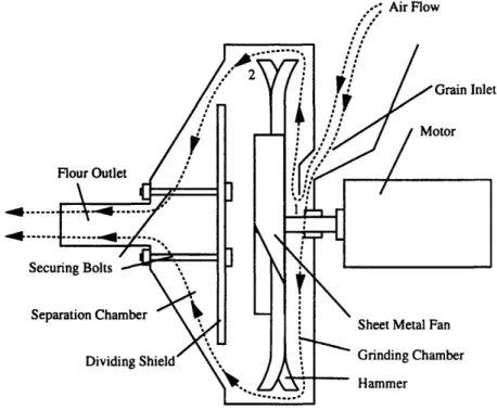
The prototype developed by the 2.72 students from the original mill produced by Bielenberg had a low throughput because the airflow through the mill was low. Their design was based on the fact that there is a low pressure region in the center of the mill, caused by the rotation of air with the hammer, and an axial pressure gradient set up by the sheet metal fan. Air is thus drawn in through the grain inlet, flows through the mill and exits through the flour outlet carrying the flour particles into the collection bag.
There is also a radial pressure gradient caused by the rotation of the air in the chamber. Pressure increases in the direction away from the center of curvature of the streamlines of the flow [5]. The air in the chamber moves with the hammer in a circular path, therefore there is a high pressure region at the edge of the chamber.
Figure 3-1 shows the flow through the mill and the low pressure region at 1 and the high pressureregion at 2. Flour Outlet Securing Bolts Separation Chamber Dividing Shield' t
Sheet Metal Fan
Grinding Chamber
Hammer
Figure 3-1: Cross-section of the 2.72 Prototype
Placing the flour outlet at the center of the separation chamber takes advantage of the axial pressure gradient, but not the radial pressure gradient. In order to increase the pressure drop across the outlet and thus increase the airflow through the mill, the outlet should be near the edge of the grinding chamber.
3.2 Design of the Flour Collection Apparatus
The 2.72 prototype was adapted in order to test the new design. The separation chamber was eliminated and the inlet was mounted directly on the frontplate of the mill. The throughput was increased, but in order for the flour quality to be maintained, a means of separation had to be developed. The simplest solution would be to use the outlet itself as the separation apparatus.
In order to verify whether the flour outlet could be used as the collection appa-ratus, several parameters of the outlet were varied and their effect on the percentage of flour reclaimed and the flour quality were measured. The length of the outlet, the radial position and the angular postion were the primary parameters tested. Other factors, such as whether the inlet is open or shut during the grinding process, also affect the airflow through the mill and were investigated to determine the optimal operating cycle.
3.2.1 Outlet Length
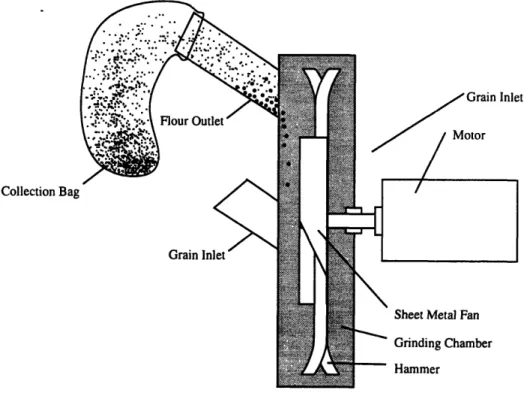
An inclined outlet tube could serve the same purpose as the conical separation cham-ber in the 2.72 mill. As the particles are carried out of the mill on the airstream, the larger particles settle out and slide back into the mill, as shown in Figure 3-2.
Collection Bag
Grain Inlet
Sheet Metal Fan Grinding Chamber
- Hammer
Figure 3-2: Cross-section of the 2.72 Prototype
In order to test this hypothesis and determine the effect of the length of the outlet tube on the percentage of flour reclaimed and the flour quality, 50 gram samples of
It
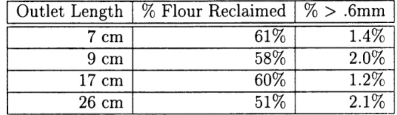
corn were ground for two minutes and the flour was collected using outlets of different lengths. The results are shown in Table 3.1.
Outlet Length
[%
Flour Reclaimed % > .6mm7 cm 61% 1.4%
9 cm 58% 2.0%
17 cm 60% 1.2% 26 cm 51% 2.1%
Table 3.1: Effects of Outlet Length on Flour Quality and % Flour Reclaimed
The length of the outlet had very little effect on the flour quality. The air flow in the outlet can be characterized by calculating the Reynolds number. The Reynolds number for the flow through the outlet was significantly higher than the critical value
for transition to turbulent flow of 2300 [5]:
V x D 70m/sec x 0.05m
Re = = 231,788
v 1.51 x 10⁻⁵m/sec2 =
231,
Since the flow was turbulent, very little settling of the particles occured. It was also found that as the length of the outlet increased, more flour adhered to the interior of the outlet, which led to less flour being reclaimed. In order to maiximize the amount of flour collected, the outlet tube should be as short as possible while still allowing the collection bag to be easily attached. This corresponds to an outlet length of about 7
cm.
3.2.2 Radial and Angular Position
Initial testing of the adapted 2.72 prototype showed that the parameters which had the greatest effect on the amiount of flour collected and the flour quality were the radial and angular position of the outlet. The grinding chamber of the adapted prototype had many surface discontinuities which led to disruptions in the flow. A new prototype with a smooth grinding chamber, shown in Figure 3.2.2, was built to confirm these results and determine the optimal location more precisely.
Inlet
Outlet
Figure 3-3: Prototype Mill for Testing the Effect of the Radial and Angular Position of the Flour Outlet on the Flour Quality and the % Flour Reclaimed.
The front plate was made of transparent Lexan, and was mounted on bolts placed every 60 degrees so that it could be rotated to test the effect of the angular position of the outlet. Outlet holes were drilled at various distances from the center of the mill to test the effect of radial position. The effect of the angular and radial position on the percent of flour reclaimed is shown in figure 3-4. The samples were sifted using a 0.6 millimeter sieve to determine the particle size distribution of the flour. The results are shown in Figure 3-5.
Angular Position of Outlet
Direction of Rotation 0°
ial Distance = I1 cm ial Distance = 14cm
1800
Figure 3-4: Effect of Angular and Radial Position on % Flour Reclaimed The outlet position that produced the finest flour with the highest percent
re-Direction of Rotation
nf Ulmmr
Angular Position of Outlet
00
al Distance = 11 cm
al Distance = 14cm
1800
claimed was 60° past vertical in the direction of the rotation of the hammer at a distance of 14 cm, or about two-thirds of the radius, from the center of the chamber
as shown in figure 3-6.
Flour Outlet
Figure 3-6: The Optimal Position of the Flour Outlet
Larger amounts of flour were collected when the outlet was placed in the vertical position, however flour quality decreased. Moving the flour outlet closer to vertical,
to about 40° past vertical could increase the percentage of flour collected without
3.2.3 Optimizing the Operation Cycle
The air flow through the mill can also affect the operation of the mill. For example, the air inlet or the flour outlet may be closed for some portion of the grinding phase. The energy consumption of the mill is lower during this time because of the decreased airflow. In order to decrease the energy consumption of the mill, the grain can be ground during a period of decreased air flow, then the air flow can be increased to collect the flour. The air flow through the mill can be restricted by sealing either the inlet or the outlet. To test the effect of sealing the inlet, samples were ground with the inlet open and with the inlet sealed, the results are shown in table 3.2. To test the effect of sealing the outlet, samples were ground for three minutes and the length of time that the outlet was open was varied; Table 3.3 shows these results.
% Flour Reclaimed
open 67%
closed 55%
Table 3.2: The Effect of Sealing the Inlet on Percent of Flour Reclaimed
Outlet Closed Outlet Open % Flour Reclaimed
0 min 3 min 90%
1 min 2 min 83%c
2 min 1 min 39%c
Table 3.3: The Effect of Sealing the Flour Outlet on Percent of Flour Reclaimed for Three Minute Runs
The amount of flour reclaimed decreased when either the inlet or the outlet was closed for any portion of the operation cycle. The energy saved by operating with reduced air flow was offset by the longer amount of time that the mill must operate to grind the same amount of grain. The most efficient operation cycle was to keep the air in-take and the flour outlet open throughout the grinding cycle. In order for the mill to operate continuously it was necessary to have a second discharge port
which was opened periodically to remove the grits from the mill. This feature was incorporated into the prototype that was built during the field testing of the mill in Senegal.
Chapter 4
Field Testing of the Screenless
Hammermill
In order to introduce the technology of the screenless hammermill developed at MIT, and to compare its performance to existing hammermills, field testing was conducted at the Sodefitex Cereal Transformation facility in Tambacounda, Senegal. Three mills were tested- the ATI Bran Discharge Mill (made according to the specifications in Du Grain A La Farine [6] with a 0.6mm screen), the ATI mill retrofit to operate without a screen and a new screenless hammermill (referred to hereafter as the Amtech mill), similar to the one which had been built at MIT.
Two kilogram samples of corn, millet and sorghum were ground in each mill, and the product was sifted with 1 millimeter and 0.6 millimeter sieves and the fractions were weighed to determine the particle distribution. Millers often moisten the grain prior to grinding it; therefore some samples were soaked in 200 ml of water for 10 minutes before grinding. The samples were ground by an experienced miller in a typical fashion and the time and energy required to grind the samples were measured. The results for the ATI Mill are shown in Table 4.1. Energy consumption increased significantly with the time required to grind the sample. This implies that most of the energy used to grind the sample was consumed by the operation of the mill (probably in simply circulating air and flour particles), rather than by the actual grinding process.
Grain Time (sec) Watt-Hours % > lmm % > .6mm
dehulled millet 88 105 3.3 11.3 dehulled corn 187 182 10.4 18.4 dehulled sorghum 195 168 17.2 wet dehulled sorghum 275 266 16.4
Table 4.1: Test Results For The ATI Mill
The ATI Mill was retrofit to operate without a perforated screen. It was necessary to modify the grinding chamber to make it airtight in order for the mill to function properly. A cylindrical chamber wall, without any holes and slightly deeper than standard screens, was fit into place and the joints were sealed. The door was first constructed out of transparent Lexan which allowed the position of the flour outlet to be easily varied and made the inner-workings of the mill visible as it was operating. Small batches of each type of grain were ground with the outlet at various distances from the center of the mill. The results of the tests are in Table 4.2, showing the product quality as a function the radial position of the outlet. The best results were obtained when the flour outlet was in the position closest to the center of the mill.
Grain Distance of Flour Outlet From Center % > mm % > .6mm
dehulled corn 13 cm 39.1 21.2
dehulled corn 10 cm 19.5 30.2
dehulled corn 10 cm 22.7 26.3 dehulled corn 8 cm 9.3 23.5 dehulled corn 8 cm 1.3 5.3
Table 4.2: Test Results For Determining The Outlet Position Of The Retrofit ATI
Mill
The flour collection bag got extremely hot while the mill was running due to the extra work required for the mill to turn through the coarsely ground grain which accumulated in the grinding chamber. To alleviate this problem, a new steel door was equipped with a discharge so that the coarse material could be removed and the mill could operate continuously without getting too hot. Two kilogram samples were
ground without the mill overheating, the results of these tests are shown in Table 4.3. The quality of flour produced by the retrofit mill was similar to that produced by the conventional mill, however the grinding time was longer which increased the energy consumption.
I Grain Time (sec) Watt-Hours % > lmm % > .6mm
dehulled corn 360 308 1.7 3.7 wet undehulled corn 261 322 6.4 18.6 wet undehulled millet 275 238 11.9 23.1
Table 4.3: Test Results For The Retrofit ATI Mill
Although the flour which produced by the retrofit mill was acceptable, it was not as fine as that which had been produced by the prototype mill at MIT. This was probably due to the fact that the grinding chamber was smaller than that of the MIT mill and the airflow within the chamber more turbulent; thus making separation more difficult. Retrofitting existing mills to operate without screens is not recommended as the energy consumption increased and the flour produced was not of superior quality. In order to achieve better separation of the fine flour particles, a new mill was built, similar to the one which had been developed at MIT. The mill was built by Cheikh Gueye of the ATI staff in Tambacounda. The materials were all purchased locally or found in the scrap heap at Sodefitex except for the motor. The motor, a 2 HP 2800, rpm AC motor, was purchased in Dakar, the capital of Senegal, for
95,000 CFA or about US$190. Some of the parts were made at a local metal-working
shop, others were made on site at the Sodefitex Facility and a few were made in a shop in Thies, a village nearer to Dakar where ATI has a field ofice. Most of the manufacturing of parts was done using simple hand tools such as chisels, hammers, files and anvils. Some tasks required an electric hand drill and grinder, which were available at the village metal-working shop. The mill was assembled using the welding equipment at the Sodefitex Facility. In all, it took about a week to manufacture the
prototype.
tip speed, as experience has shown that the tip velocity of the hammer must be at least 70 meters per second to ensure efficient grinding. The motor which we used was
rated at 2875 rpm, rather than the 3500 rpm of the prototype, therefore the length
of the hammer was given by:
V 70
L > = 0.465m
7rr X = 6 o 47.92
A 49 centimeter long hammer was used in a grinding chamber which was 51
centime-ters in diameter.
Testing the prototype at MIT showed that the optimal location of the flour outlet was determined by the diameter of the mill, the direction of rotation of the hammer, the desired fineness of the flour and the desired ratio of flour to grits. The Amtech mill was constructed with a 5 cm diameter outlet was located approximately 15 centimeters (2/3 of the radius) from the center of the mill at an anglular position of 30 degrees from vertical, measured in the same direction as the rotation of the hammer. This mill was also fit with a transparent Lexan door, in order to observe the grinding process, as shown in Figure 4-1. The Lexan door was fitted with a grits discharge gate to prevent the accumulation of coarsely ground material, allowing the mill to operate continuously. The grits discharge was located at the bottom of the mill where a spring-loaded plate covered a hole in the door. The plate was lifted by pressing on the handle. The position and operation of the handle was such that the grits discharge was able to be opened by pushing against the handle with the leg, leaving the hands free to regulate the flow of the incoming grain.
The operation cycle of the mill was based on the results of testing the prototype at MIT. The flour outlet was open continuously throughout the operation of the mill. Once the mill had come up to speed, the hopper gate was opened and grain was allowed to enter the mill for about five seconds. Then the hopper gate was closed for about ten seconds. The grits discharge was opened for five to ten seconds during which time the grinding chamber was emptied of all remaining particles. The cycle was repeated until the grinding was completed. The fineness of the flour was
unaffected by the operation cycle, unlike conventional mills where the feed rate of the grain into the mill does affect the fineness of the flour produced. The fineness of the grits, however, was strongly affected by the operation cycle, specifically by the length of time the grain was ground before the discharge gate was opened. The ratio of flour to grits was also affected by the length of time before the grits discharge was opened. The discharge portion of the cycle was longer than desired; however this can be improved by increasing the size of the grits discharge gate.
Two kilogram samples of dehulled corn, sorghum and millet were milled in the Amtech mill, the results of these tests are shown in Table 4.4. The time required to grind the sample varied considerably as the operating cycle was being optimized to minimize the energy consumption. The mill was the most efficient when the grinding took the least amount of time.
Grain
Time W-Hrs % Flour % > lmm % >.6mm % < .6mm
dehulled millet 480 112 19.9 1.6 10 61.7 dehulled millet 295 70 16.3 1.25 15.4 61.85 dehulled corn 300 112 29.2 2.3 20.9 41.9 dehulled corn 210 56 18.8 8.4 21.5 50.8 wet undehulled corn 270 126 18 10.7 38 32.4 dehulled sorghum 305 98 20.3 6 17.8 44.4 wet undehulled sorghum 372 112 11.9 8.3 36.5 47.5
Table 4.4: Test Results For The Amtech Mill
The flour collected from the flour outlet was much finer than the flour produced with the ATI mill. The grits that were collected were similar to the mixture produced by the conventional hammermill, however it was much easier to sift as the fine particles which tend to clog the sieve had already been separated out by the flour outlet and collected there. Samples of the product were also subjectively evaluated by the Cereal Transformation Staff and some women from the village and found to be of very high quality.
The mill was also tested to see if it could be used to grind grain from which the hulls had not been removed. If the hulls were able to be removed during milling, it
would not be necessary to dehull the grain prior to grinding it. This would eliminate another time-consuming step from the grain processing. 2 kg samples of un-dehulled grain which had been soaked in 200 g water for about 15 minutes before milling were also milled. There were small quantities of hulls in the flour and the rest was in the grits. In the case of the corn, it was quite simple to sift out the hulls with a 1 mm sieve. Sorghum and millet hulls were not as easily removed, as the particles were smaller, however most of the hulls could be removed by sifting and winnowing. It will be necessary to perform further subjective tests to determine whether the final product is satisfactory. Mr Ndiaye of the Sodefitex Cereal Transformation Staff indicated that in some regions, maize is consumed with the hulls and therefore the performance of the mill could be acceptable. Furthermore, Cheikh Gueye of ATI reported that the women who used the experimental bran discharge mill in Ndiane, Senegal mixed the flour made with the un-dehulled grain with flour made from dehulled grain in order to achieve an acceptable product.
Another critical element which contributes to whether or not the screenless ham-mermill will be accepted is the cost. Production costs were estimated by determining the materials cost and adding 40% for labor. The complete materials lists for the Amtech mill and the ATI mill are shown in Appendix A. The cost of materials and labor required to make the screenless hammermill by this estimate is about 260,000
CFA or about US$ 520. A conventional mill costs over 1,000,000 CFA (US$ 2080) or
almost four times as much. Estimates of the costs of operating the ATI Mill and the Amtech Mill are shown in Table 4.5.
The depreciation of the mill and the motor are based on their prices in 1994 (after the devaluation of the CFA). Since the mills that were tested were powered by electric motors, the estimate assumes that the mills are operated by electic motors with a life of 2000 hours. The thoughput and energy consumption were based on typical values for milling dehulled corn and an estimated cost of 100 CFA/Kw-hr. Based on these assumptions, the Amtech mill reduces milling fees by more than 40 percent. This major reduction in cost is primarily due to the improved enrgy efficiency and the reduced manufacturing costs.
ATI Mill Amtech Mill
Mill Depreciation 1,000,000 CFA / 3000 hrs 260 00 CFA / 3000 hrs
Motor Depreciation 360,000 CFA / 2000 hrs 95,000 / 2000 hrs
Screen Replacement 18,000 CFA / 200 hrs
Hammer Replacement 20,000 CFA / 400 hrs 1000 CFA / 400 hrs
Mill Operator 1500 CFA / 4 hrs 1500 CFA / 4 hrs
Throughput 70 kg/hr 50 kg/hr
Energy Consumption 90 Watt-hours/kg 30 Watt-hours/kg
Milling Costs / kg 24.8 CFA/kg 14.7 CFA/kg
.05 $/kg .03 $/kg
Chapter 5
Conclusion and Recommendations
The initial field testing of the screenless hammermill shows that it is a very promising technology. It satisfies a number of criteria which make it a better mill for developing countries. It is easier and less expensive to manufacture. It is possible for the mill to be produced out of a small metal-working shop without importing any parts other than the motor. It is more robust due to the elimination of the delicate screens. The final design of the screenless hammermill is shown in Figure 5-1 and incorporates many new features which enhance the design.The hammer is mounted directly to the motor shaft, eliminating the transmission and thus reducing the number of parts and making the mill less expensive. The ham-mer blade is easier to manufacture and less expensive than those in used conventional hammermills. It is also easier to balance which reduces bearing wear. The smaller hammer design allows the mill to be powered by a much smaller motor. Conventional hammermills are generally powered with motors of at least 5 horsepower. The screen-less hammermill can easily be run by a one or two horsepower motor which allows for considerable energy savings, as shown in figure 5-2.
The grits discharge allows for continuous operation of the screenless hammermill and produces a product which is more attractive to the women who use the mill. Different foods use different sized particles of grain, so traditionally, the women sift the flour and grits mixture to get the proper sized particles for the dish they want to prepare. The screenless hammermill produces a product in which the fine flour is
Grain Hopper
n Flow Regulator
mmer
Figure 5-1: The Amtech Screenless Hammermill Grair
200 U, 0 0I 3V E
l00
Uo 0 W bOtConventional Mill Amtech Mill
Figure 5-2: Energy Consumed While Grinding 2 Kilograms of Corn
already separated from the coarser grits. This eliminates the time-consuming task of sifting out the flour. If further separation of the grits is required, the sifting process is much quicker as the fine flour particles which tend to clog the sieve have already been separated out of the mixture.
The grits discharge is designed so that it can be operated by simply pushing against the handle with the leg. This gives the miller the freedom to use both hands to regulate the flow of incoming grain. Pushing the handle opens the grits gischarge gate and allows the grits to be collected in a cloth bag which is attached to the end of the discharge.
The grain flow regulator uses a sliding mechanism to adjust the flow of grain into the mill rather than the rotating mechanism found on some other mills. Grains often become lodged in the rotating mechanism and prevent it from closing entirely. The sliding mechanism is less prone to this jamming and thus better regulates the flow of grain into the mill.
There is an opening in the grain inlet which provides the visual feedback to the miller and allows air to enter the mill. Because the airflow through the mill is critical to its operation, it is necessary that there be an unimpeded air intake.
A disadvantage of the mill is that the miller is required to regulate the inflow of grain and operate the discharge during milling, which requires some additional work on the part of the miller. This task, however, is not arduous as village mills typically grind small batches of grain at a time. A women grinds only as much grain as she needs for a few days at a time, or between two and ten kilograms, depending on the size of the family. A miller would therefore only be required to repeat the cycle three to twelve times when grinding a batch of grain.
When viewed in the context of appropriate technology, the screenless hammermill is an improvement over existing hammermills. It is significantly cheaper to manu-facture and can be produced locally. It is in the price range which is affordable by a small group of farmers or a women's cooperative. It stimulates the local economy, as it can be built by local craftsmen rather than being imported and sending the money outside the region. It is easier to maintain and does not require imported parts for it's maintenance. The lower energy consumption decreases consumption of non-renewable energy sources and it could possibly be adapted to operate using solar energy or by an internal combustion engine fueled by vegetable oils. The underlying principles of the design are simple and the mill is easily understood and operated.
Further field testing and user feed-back is required to determine whether the screenless hammermill will become an accepted technology in other regions of the developing world. The technology transfer, both of the operation of the mill and of manufacturing the mill, must be done with care in order to ensure its success.
It is recommended that the prototype in Senegal be completed by fitting it with a steel door with an enlarged discharge hole to replace the Lexan door and to attach a grain hopper to the mill. To determine whether the technology will be an acceptable one in Senegal, the mill should be taken to several villages and many users should be interviewed to determine whether the mill and its product are satisfactory. The villages should be located in different regions of the country where different staple grains are grown and different dishes prepared in order to determine which markets are satisfied by the new mill. Initially the mill should be tested with dehulled grain, and if it is found to be satisfactory, un-dehulled grain can be tested. Finally, a workshop
that would be interested in producing the mill should be located and instructed in its fabrication. Once the mill has been proven to be successful in certain regions of the country and local artisans have been instructed in its manufacture, agriculture extension workers and development workers should be informed of it so they can help introduce the mill to potential milling groups.
To continue the dissemination of the technology, suitable organizations in other countries should be contacted and informed about the mill. A demonstration mill should be built and taken to these countries to determine if it might be successful there and if so, the field-testing and technology transfer process can be repeated. If the technology transfer is successful, the screenless hammermill can make a significant contribution to the development of rural areas by improving the life of rural women and providing local employment opportunities.
Appendix A
Materials Lists
Table A.1: Materials List for the Screenless Hammermill
Item Quantity Cost (in CFA)
sheet steel 2m x m x 5mm 45000 sheet steel 0.5m x 0.5m x 2mm 1187 sheet steel im x m x mm 800 leaf spring 50cm 1333 channel steel 80mm x 40mm x 3m 11000 channel steel 30mm x 15mm x 0.5m 1500 shaft assembly 1 23000 steel rod 10mm x 10cm 100 spring 1 100 threaded rod 12mm X 30cm 3000 bolt 16mm x 100mm 300 bolts 2 12mm x 30mm 220 bolts 4 6mm x 30mm 120 paint 2 kg 3000 motor 2 HP 2875 rpm 95000 materials ] 185660
labor (40% of material costs) 74264
total CFA 259924
Table A.2: Materials List for a Conventional Hammermill
Item Quantity Cost (in CFA) sheet steel 2m x m x 5mm 45000 sheet steel 2m x m x 3mm 22000 sheet steel 2m x 0.5m x 2mm 4750 plate steel 60mm x 10mm x m 1833 plate steel 30mm x 8mm x 2m 3166 plate steel 20mm x 5mm x 8m 8000 steel rod 16mm x m 683 steel rod 40mm x m 9500 steel rod 100mm x lm 1020 angle iron 60mm x 60mm x 4m 5666 angle iron 45mm x 45mm x 4m 3666 channel steel 80mm x 40mm x 12m 44000 pulley shaft/pulleys 17 9000
pillow block bearings SKF 3 509 / 1209 K 120000
collars 2 4500 seals 2 1500 motor mounts 4 32000 belts 2 19000 screen 0.6mm perforations 9000 screen 1mm perforations 9000 screen 2mm perforations 9000 screen 4mm perforations 9000 paint 2 kg 3000 bolts 18 14mm x 16mm 4500 bolts 12 12mm x 15mm 1500 bolts 4 12mm x 30mm 440 bolts 6 10mm x 30mm 600 bolts 4 8mm x 30mm 160 motor 5 HP 2875 rpm 360000 materials
]
742084 labor (40% of material costs) 296833total
[
CFA 1038917Appendix B
Table B.1: Parts List for the Amtech Hammermill
Item Part Number/Description Quantity
Backplate HM-201a 1 Chamber Wall HM-201b 1 Hinge HM-201c 1 Legs HM-201d 2 Feet HM-201e 2 Frontplate HM-202a 1 Flour Outlet HM-202b 1 Grits Discharge HM-202c 1 Grain Inlet HM-202d 1
Front Hinge HM-202e 1
Hinge Pin HM-202f 1
Discharge Handle HM-202g 1
Discharge Hinge HM-202h 1
Discharge Hinge Pin HM-202j 1
Discharge Plate HM-202k 1
Discharge Gasket HM-2021 1
Hopper Chute Backplate HM-203a 1
Hopper Chute Front HM-203b 1
Hopper Chute Back HM-203c 1
Hopper Front HM-203d 2
Hopper Side HM-203e 2
Grain Flow Regulator HM-203f 1
Hopper Bottom HM-203g 1 Hammer HM-204 1 Fan HM-205 1 Disk HM-206 1 Spring 1 1 Bolts (w/nuts) 15mm X 120cm 2 Bolt (w/3 nuts) 12mm x 90mm 1 Bolts 10mm x 40mm 2 Bolts (w/nuts) 5mm x 20mm 2 Bolts 5mm x 10mm 6
v-
v vv
L
X CA t P p Fag p M n taBa
( zII
0 I-.r
I (H m r) -I n I- r ,a g 34 Z X £4 mn 0 X m X I .. O Ln zI
-I w T 0I
cn sL | |r m P ¢tr , P p 0-v I (IC cN D -p z I. p LA r r A I P1 z a z 0 1 I ;o M 5 0 --4 '4 5i D z
I
l o _1o
w cD3
wrr
m r t3r
0 P, 0 0 0 LA 1 17 1 1 14---j 1~~~
r?~
F
-o I I_P
·-h
r I-z A z n m 1 I -4 z m i 1r"
I
0rC 9 -4 I '-40 x Lin 0 0 ~A I-rr
r-, [o C-mr)
rr A_ 2. zD I -11I
40 0" NAn a)N (11 -1D D m m in rfl x inX I X Wo E0 0o -P °t 3 r+ a 2 p O i r e 1 "7 B p4P,1 . W +a W I I, C V ' .44-I w A Iz oD rl) C:0. -r z
-I
I
0 cr w N ,D Ln | | - |T a. Op S d, n IAt0o s #$N NRp ' o _ _ ex| x $ I-rr I A ai 2 (A n e z pi m m W
I
II
.1 mr
I-I C-,I 0I 0'E V D 0 C-nI LA x -1 0QI LX x 0 X X o o -. I Lr 3 3 is | -II
II-I E D D I'u / - ILI Iv o DP5 T 5-fo _ (D cD-. m 3 ,+
.,
- O CD -"P r.. r-I-z
CI P1 z 9I
C,Z r O C 2 3.w It -I o 0" N i0N m r tZ M z o m x rn X O X X b UIl l--zZ -4 m s r Z 3 -. . 0 u , p O 0 E _O030 tr 31 -R 3 0 P in C I
I
n, .4 F·r
m C) II
o D> z R -4 , mX i x 0en ;3 W Ix LAI
0I 0 cn mo r 5 D. DsL
J
p ml , o *F - I, 0-+ P ZQ S 0 D n 21 O ° tr N .-1:1 -I KI
no m I-E5 m z PM z '4 K z -4 4 'A 0 P Ul x x oI
C c-l en z O -l4 m '4 3 n) P P X X 3 n D p -u pco I x 0 3 3 Ii n ' x x o o S | lI_ - ll II l- l-r I-I z z z m C,, z-1 x rn IC, -t C, 4~r C} z
I
ru Co 0 a x tn A0 x x X CAA1 0I-
r-o
z
--I 3 C- (-z .41 (4< X, --4 m n -. ru a, n -| -I- __ I __4I Cz -4 m 3
~~~~0w
> -1xnn nnogeTco 0 'D3,7 3 7 ~~ E~P 'I4 * ~~o+ .0OU L04 ID o~y
1~3nOI~
ec~Jl
3. Cn I 0 IX) 41 I-r T r-C _9 ?o
z
-I C,. P1 Im r-R X X X D x O rX C~ o x 0+ m IC1-I
0 iD cn -|-z m 3 1p 0 Al - c -P i 0i Op :=~4 1I5 1 a 2.1 .T 'I -r IC z z ru 0 ru r I5 1 m z ,4 0 0 0 x i+ p U1 x p m
0
z
--t -Dr--I
m 2 C) 0 U1 GDI
en ID Un X x o o0 L0 ___ _I _· | l ---z -4 m o n p 00-4 L- ' m 0 p 0. n ru 1+ L n U 0 m P- p U 5 r: 0 wI Co ro ro -4 m
r-i: C -I4r
m-I
r r x 0 o 14. op n m z X (.. w ': I l- III_
l- |-Lz 0 .- I o ru -u v' v v I °m 0 . c~rp 0 3 NU C 7 0 10 ' IR
I
0oU re TU m t:1 C-) '1I D' r -. I j m Az0
0 xgm
2 o ul 0 (1) ..px x Ul0 I 3.I
g o '-4 \I U1L .-2 0 C, 11 · 0~ 3 0 9 0 p ru r Z . 'o 9~ -I V tP 0o E S 6 Q -rx
I
o no e, -I. F, G4-4z
I-Zr
m --4 r z ' a m z A x o In o LAC -r-D 0I
o -4 · · l l I-r z Z R 0 0 - in2 r mz -4 x '3 -4 m m W x I. o X x U0 I i I I I II I I I I I I
III
II
II
Q o P P v v oP0 n po - 9 , 3 I ru 0 o V LAeF U} cn b m I -- II
m z r ILI I 3 c-r CD nI-T
I Q p I-P z m z z !, z 3, m z rn z -I -4 m XC zI
o noI -II
r m '-4z
m "g x. in x r-J 0 XCI
c) C1 o o ID en z -r V) :Z x p 1+I F. tn rg rp X X o 14 0o |I_ -- |l- -I I Im I'"' ILI
3-) l 0 n 3 3 p a P rL -3 a 3-Q r r i< =,X X X o '. eI o z 0 --I P1 p -rD 3 3 x 3 3 n P 3 Ca no To C, Go r-C-) Itj
m I z m mz
r-m z I -I 0 r Ln - - | II IIUn o p p z -4 m
3
LA rL t P Q : n r ~+ I 1 'I 3 0 P r>6\) I o , nP * PQ0 pp-v y 5 p 4P -onz~
3
W m ' CD CD3 p rm0 IAQ ru I 4+ cl 0 4+J cI
m *oI
-4 -, c-i Iz
mmz
m mC-I
a
r-o o 4 M <0 "n I'Dl r F , C z z - x m x0 o n ri IU t It
IIo
p z o -4 p -m '3 0I
(I
L. r r I x m z !i E 2 z I 2 -g m (I m m 0 r x ul x o x 0 m 0J C ,DI
F-I
In
0 -uz
Z X x o en so I . -II I I I Ir ° Z x 0
(n
0
n z A x mX 0 o x x0 cn + '3 c C [] z '30 J p tn 1+ 3 I _ 3 a "rI
I zLr-tj
C-H -r I mr-r
m M. w .D 03- I-x2 m z 3-M m z -4 I, '4
II
ror
3 3 P Q ---3 c x0 A+ o i+ 3I
crl 0 0 ID 0 C-, mT-I
nr P1 0 m r-z D -I m v4, X xX o Ue o 3 p 3 3 I j - |-. , -.-Ir D r r 2 3
Be
-, x D 70 m n2 z -4-x W .. p x 0 LAi
I C o w ;i I C F, -U m (A I 70 0 X z (AI
ah Co ID Cn I -- - S-0 3 1 0 0 0 0 0 X4 0 4+ 1D V 1 3 I 0 _7 C z
I
m I') w.-I
-0 O P' r-P F D 1 r o 0, z -x mX x CM o X0i
CDI
a
ru N1 I . __ I |r r !ix D 0 -Z O z < X mX m 0 mnxO m ? In m o 3 3 p o o I Sli
-7
' !I CI\
>
z -vz p 3 I !-rnp F+ ro N, Ul 3 3 a p I S II
3,o
Dl I -C C 0I
\I I -( o C-) r C I id C)r
-4D1 S- ! -- - ----( It
I I i1~~~~~~~~~~~~~~~~~~
r \ . . I . .!T . . & I Illl II . l _ i u c -- - - -. - - - -I :3 i r i I IF P
Zx
' m Z 1 o rLen -1 i VVc +V 3 ,. yID'a 'I IS tr n V m L. 3-gm V flrt 4p z IC w 3 m -4 M m m zi SI
.D / \C enl -o -r mo
I
c
rlmz
--A x x X o O o | | -|-I
I
I
o O z D -4 Px Sr Uw WD C, tq t I ~ 7 S 3 P 1" 4 r o A 1 z C, rn z mz I-4 3. C'or (1) c, x x o cn x,, (D C CT,I
CD (nI
r I D P1 x xo o 0 L-IaII
I l. --i:r 0 - r Z z z X X mu, m X m X o 0. 0D bi z 0 -4 14 ) Q S 0 . S z
I
o w ttl z!!I
Fl M -v -v m Xz
-4 C-) 7, tz -4I
o1 'D n T-|II
-r M -| D r -r m -ZX A XX m Zo 4 Z O rnen - L. 0 x x 0 _ X Xo r, O en o Z D -4 _ M le U z 3 * Q.u. x 0 m " O- ,:r E . d- 3 , 'C .+ Vu i MI', I m~ Z I -r T 0 m M,
I
C m-v 0 ttj I 0 Zs 0 3I
rt .5r
\0 eN N CA -.- I_ | --II 0 -3 ,IL l-, r-mul x m mi Z 0 > X n 0 X Ln I. 01 p -yn F _ B_ 2 oo -4 m x, p 4+ -3 ru 3 3 4+ tU ' mp z z
I
o C) -TI -4 r C3z
0 m C) C F--H cO M £* z .1t 0x-r D 3 C) I NSo o 0s I'D Ln___
l S-| . - - -L I L t-( ur D Cm g of Z r D, X A X
n
a mu, z Al M - n X XOo n i 0 -0 z m I, -I p ro 3 3 11' tA 4+ ID C)) w iv4 ,,,..-. z :s I n,0 Co wI
-r E3m-d--:
C, I -4 ro .2 ID In --|-i
-Z O - r A z 0 n X -o o mX p xeno 0D ZA !S A
I
a Rl)roI l I x m -, I m C-)I
--W DI
No
ru rn No Cu |-II
Z m -- I o -. "S P 3 p0 p3 p n T-P r-m Z m (4 0 z ? z -.4 mX 0 -Il0 m x M~i 0 . p)~ x cr0 XA
LII
I bT b3 -I-I--IT r E p 3 z rop-0 z 0 r0 o N n ID - l - l
-M~
' I I t' i9 I [ lL _ 1 II, L\ ZA-\ .. -II- I-z 0 ;o m