, )f < ; e + 4 I r:I ,,
.
- I
e7
i t .
DESIGN OF TUNABLE RESONANT CAVITIES
WITH CONSTANT BANDWIDTH
L. D. SMULLIN
TECHNICAL REPORT NO. 106
APRIL 5, 1949
RESEARCH LABORATORY OF ELECTRONICS
MASSACHUSETTS INSTITUTE OF TECHNOLOGY
---The research reported in this document was made possible through support extended the Massachusetts Institute of Tech-nology, Research Laboratory of Electronics, jointly by the Army Signal Corps, the Navy Department (Office of Naval Research) and the Air Force (Air Materiel Command), under Signal Corps Contract No. W36-039-sc-32037, Project No. 102B; Department of the Army Project No. 3-99-10-022.
__ _I _ __ I
MASSACHUSETTS INSTITUTE OF TECHNOLOGY Research Laboratory of Electronics
Technical Report No. 106 April 5, 1949
DESIGN OF TUNABLE RESONANT CAVITIES WITH CONSTANT BANDWIDTH
L. D. Smullin
Abstract
The design of tunable waveguide cavities is examined to determine the type of coupling susceptance required to give constant QL or constant width. It is shown that the inductive iris commonly used causes the band-width to vary radically as the cavity is tuned. A capacitive iris, however,
produces a reasonably constant bandwidth.
__ ___I_ __
--I·--DESIGN OF TUNABLE RESONANT CAVITIES WITH CONSTANT BANDWIDTH
The design of resonant cavities and waveguide filters to have specified bandwidths or transmission characteristics has been dealt with by several authorities (1)(2)(3). These analyses have been concerned with the design
about a specified center frequency. One finds, however, that it is often
required to build a cavity or a filter which is tunable over a frequency range of 10 per cent or so, and whose bandwidth shall remain essentially constant over this range. This latter requirement is not met by most prac-tical engineering designs with which the author is familiar. The reason for this will be pointed out, and alternative designs suggested in the following sections.
Two-Terminal Resonant Cavities
A resonant cavity formed by shorting one end of a length of waveguide, and coupling to the external circuit by a hole in the opposite end, is simple to analyze and the conclusions may be extended directly to more complicated resonator structures.
We will consider the cavity of Figure 1, consisting of a length of
wave-guide of characteristic admittance Yo of length , shorted by a plunger at
one end, and connected by the shunt susceptance B to the external transmission line.
SHORTING
jb=jB/Y
oPLUNGING
Fig. 1 Two-terminal resonant cavity.
We will confine our attention to a single waveguide mode. The resonant frequency of the cavity will be defined as that at which the input admittance
(looking into the coupling susceptance) is pure real. This will occur when
Yo cot 2= B g that is, X = cot1 _ + n (n = 1,2,...) g o -1-... _ --- --- -·--- ----
·---If b = B/Yo >>l,
g
t E~ 6+ nr
where g is the guide wavelength corresponding to the free-space wavelength .
The loaded Q of such a circuit may be written as
QL = ()a, dt
where B' = Y (b - cot 2Qr/ ), the total loading of the cavity is due to the conductance G = Yo(l + b2gc¶, and Yogc is the equivalent conductance, due to
cavity losses, which appears at the center of the cavity. From this, the loaded Q of a "half-wave" cavity is (4)
2
QLl = 2 (1)
=2+
gc
We will limit the argument to nearly lossless cavities (gc<< 1/b2).
Then the coupling susceptance required to produce a given value of QL1 is
b + Q/---L1 . (2)
g Substituting
lg =
where c is the cutoff wavelength of the guide, we get
b + 2L1 (2a)
This is the functional form of the coupling susceptance, b, required to maintain a constant value of QL1 (actually a constant value of external Q).
If the requirement is that the bandwidth have a constant value of Af cycles/sec, where Af = f/QL,' then we find
b + 2ci A?] [
for b2gc<< 1.
-2-3 d- INDUCTIVE IRIS
SYMMETRICAL ASYMMETRICAL
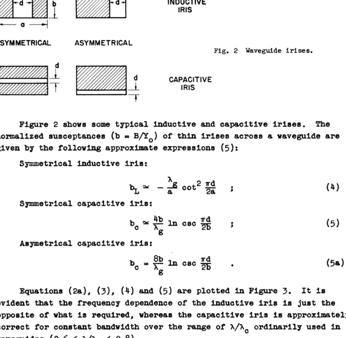
Fig. 2 Waveguide irises. I
I
T
CAPACITIVEIRISFigure 2 shows some typical inductive and capacitive irises. The
normalized susceptances (b = B/Yo) of thin irises across a waveguide are
given by the following approximate expressions (5): Symmetrical inductive iris:
bLe
- cot2d ; (4)bL = l tga ot 2a
Symmetrical capacitive iris:
b e 4b ln ccrd (5)
Asymetrical capacitive iris:
bc 8b 1ccd (5)
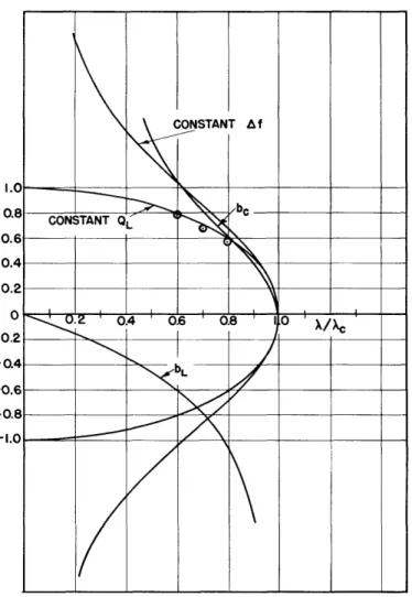
Equations (2a), (3), (4) and (5) are plotted in Figure 3. It is evident that the frequency dependence of the inductive iris is just the opposite of what is required, whereas the capacitive iris is approximately correct for constant bandwidth over the range of A/Nc ordinarily used in
waveguides (0.6 < /Nc < 0.8).
The question arises as to why capacitive irises are so seldom used for
coupling to resonant cavities. If high values of loaded Q are required
(QL c- 5000), coupling susceptances of the order of b = B/Yo = 40 are required.
Examination of Eq.(5) indicates that a really microscopic gap, d, would be required. On the other hand, if one is concerned with Q values of the order
of 100 or 200, then we find that we require b - 6. With an unsymmetrical
iris at A = 10 cm in a 1 1/2 x 3-inch waveguide, this would require a gap
d 0.040 inch. Although this is a small gap, the tolerances are not severe,
since the capacitance varies only as the logarithm of the gap. In practice, since the iris would not have zero thickness, a somewhat larger gap would be required to produce this value of susceptance.
Fig. 3 Coupling susceptances necessary to give constant QL and constant Af.
An inductive iris with the same value of susceptance (b = 6) would have an opening d - 0.88 inch. Thus, there are obvious mechanical
advan-tages in favor of the inductive iris. On the other hand, one can attain a nearly constant bandwidth by the use of a capacitive iris, and this may
justify the extra difficulty of construction.
Four-Terminal (Transmission) Cavities
The two-terminal resonant cavity is seldom used in microwave filters except as a spot-frequency-rejection filter. Double- and triple-tuned
filters (2), consisting of tandem resonant elements connected by lengths of transmission lines, have found extensive applications in microwave-communi-cation apparatus. The basic element of such filters is a four-terminal resonant cavity. Figure 4 illustrates the usual form of construction of
such cavities. It is a section of waveguide of length 2, coupled by input
and output susceptances b and b2, and tuned by a screw at the center, whose
susceptance is 2bo . The loaded Q of such a cavity, when coupled to a matched
load and matched generator, is
-4-2
r, i
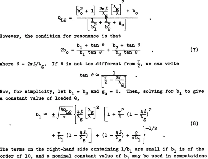
QL2
however, the condition for resonance is that
b1 + tan b2 + tan e
2bo = b tan
e
+ b 2 tan · (7)1 2
where
e
= 2ri/wg. If e is not too.different from , we can writetan
e
1
[2
aNow, for simplicity, let b = b2 and g = 0. Then, solving for b to give
a constant value of loaded Q,
+
+
L2
4{[4
2
b +1 + (8) (4]
+
4
£+-'
2 -1/2
+ EK (1 + ' A 1 9 1The terms on the right-hand side containing 1/b1 are small if b1 is of the
order of 10, and a nominal constant value of b1 may be used in computations. TUNING SCREW
j 1 2jo
UJB
2 Y0:IKsl-e--l
Fig. 4 Four-terminal (transmission) resonant cavity.
The points indicated by circles on Figure 3 are computed from Eq.(8), for b = 10. Again, a capacitive iris is a far better approximation to the required susceptance than is the inductive iris.
Numerical Results
The accuracy of these computations, based upon equivalent circuit concepts, may be gauged by a comparison between the computed behavior and the experiment. The experimental values were furnished by W. Sichak, of
-5-__I
1_1____
____I
_
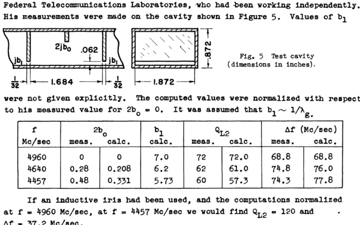
Federal Telecommunications Laboratories, who had been working independently. His measurements were made on the cavity shown in Figure 5. Values of bl
2jb
o.062
· t--~ 1.684- -1.684
L
,-.TX
8 I lFig. 5 Test cavity (dimensions in inches).
were not given explicitly. The computed values were normalized with respect
to his measured value for 2bo = 0. It was assumed that bl- 1/g.
f 2bo b QL2 Af (c/sec)
Mc/sec meas. calc. calc. meas. calc. meas. calc.
4960 0 0 7.0 72 72.0 68.8 68.8
4640 0.28 0.208 6.2 62 61.0 74.8 76.0
4457 0.48 0.331 5.73 60 57.3 74.3 77.8
If an inductive iris had been used, and the computations normalized
at f 4960 Mc/sec, at f = 4457 Mc/sec we would find QL2 = 120 and
Af 37.2 Mc/sec.
Conclusion
Two-terminal and four-terminal tunable waveguide cavities have been examined to determine what form of coupling susceptance would be required to give constant loaded Q or constant bandwidth. Capacitive irises have a frequency dependence which is approximately that required to produce
con-stant bandwidth. The frequency dependence of inductive irises, on the other hand, is such as to produce a large variation of bandwidth over the tuning
range of the cavity.
In the approximate range of 50 < < 300, it seems practical to build capacitive irises to be used across rectangular waveguides.
References
(1) "Microwave Transmission Circuits", (G. L. Ragan, Ed.) McGraw-Hill, 1948, Chap. 9 and 10 (A. W. Lawson, R. M. Fano).
(2) R. M. Fano and A. W. Lawson, Proc. I.R.E. 35, 1318 (1947).
(3) P. I. Richards, Proc. I.R.E. 4, 145P (1946).
(4) "Microwave Duplexers", L. D. Smullin and C. . Montgomery, McGraw-Hill, 1948, Chap.II. (5) Waveguide Handbook, M.I.T. Radiation Laboratory Report No. 43, Feb. 7, 1944.
-6-r/ .